Tripp Lite SmartRack Owner's manual

Category
Racks
Type
Owner's manual
1
SmartRack
Enclosures
Owner’s Manual
WARRANTY
REGISTRATION
Register online today for a chance
to win a FREE Tripp Lite product
www.tripplite.com/warranty
Enclosure Installation
Enclosure Configuration
Equipment Installation
Storage and Service
Warranty and Warranty Registration
Español
Français
4
7
11
13
14
15
29
1111 W. 35th Street, Chicago, IL 60609 USA
www.tripplite.com/support
Copyright © 2010 Tripp Lite. All trademarks are the sole property of their respective owners.
Preparation
4
Unpacking
4
Placement
5
Leveling
6
Ground Connection
6
Adding or Removing Front and Rear Doors
7
Reversing Front Door
7
Adding or Removing Roof Panel
9
Adding or Removing Side Panels
9
Adjusting Mounting Rails and Cable Management Rails
10
Combining (Baying) Enclosures
11
Installing or Removing Cage Nuts
12
Specifications
13
Feature Identification
3
Overview
2
Important Safety Instructions
2
2
Important Safety Instructions
SAVE THESE INSTRUCTIONS
All sections of this manual contain instructions and warnings that should be followed during the installation and use of the SmartRack Enclosures
described in this manual. Read all instructions and warnings thoroughly before attempting to move, install or use the SmartRack Enclosures described in
this manual. Failure to comply will create a risk of personal injury and property damage and may invalidate the warranty.
• Keeptheenclosureinacontrolledindoorenvironment,awayfrommoisture,temperatureextremes,flammableliquidsandgasses,conductivecontaminants,dustand
direct sunlight.
• Leaveadequatespaceatthefrontandrearoftheenclosureforproperventilation.Donotblock,coverorinsertobjectsintotheexternalventilationopeningsof
the enclosure.
• Theenclosureisextremelyheavy.Usecautionwhenhandlingtheenclosure.Donotattempttounpack,moveorinstallitunassisted.Useamechanicaldevicesuchasa
forkliftorpalletjacktomovetheenclosureintheshippingcontainer.
• Donotplaceanyobjectontheenclosure,especiallycontainersofliquid,anddonotattempttostacktheenclosures.
• Inspecttheshippingcontainerandtheenclosureforshippingdamage.Donotusetheenclosureifitisdamaged.
• Leavetheenclosureintheshippingcontaineruntilithasbeenmovedasclosetothefinalinstallationlocationaspossible.Thecastersaredesignedforminorposition
adjustmentswithinthefinalinstallationareaonly.Thecastersarenotdesignedformovingtheenclosureoverlongerdistances.
• Thecastersarenotdesignedtoprovidelong-termsupportfortheenclosureafterfinalinstallation.Usethelevelerstoprovidelong-termsupport.
• Installtheenclosureinastructurallysoundareawithalevelfloorthatisabletobeartheweightoftheenclosure,allequipmentthatwillbeinstalledintheenclosure
andanyotherenclosuresand/orequipmentthatwillbeinstallednearby.
• Donotpushtheenclosurefromthesidepanelstomoveit.Pushingfromthesidepanelswillcauseatippinghazard.
• Whenrollingtheenclosureonitscasters,alwayspushitfrombehind,neverpullittowardyou.
• Arollingenclosurecancausepersonalinjuryandpropertydamageifnotproperlysupervised.Ifrollingtheenclosuredownarampisrequired,useextremecaution.
Donotattempttouserampsthathaveaslopesteeperthan1:12.
• Usecautionwhencuttingpackingmaterials.Theenclosurecouldbescratched,causingdamagenotcoveredbythewarranty.
• Save all packing materials for later use. Repacking and shipping the enclosure without the original packing materials may cause product damage that will void the warranty.
• Donotre-shiptheenclosurewithadditionalequipmentunlesstheenclosurewasshippedwithaspecialshockpallet(“SP1”modelsonly).Thecombinedweightofthe
enclosureandinstalledequipmentmustnotexceedtheloadcapacityofthepallet.TrippLiteisnotresponsibleforanydamagethatoccursduringre-shipment.
• Useofthisequipmentinlifesupportapplicationswherefailureofthisequipmentcanreasonablybeexpectedtocausethefailureofthelifesupportequipmentorto
significantlyaffectitssafetyoreffectivenessisnotrecommended.Donotusethisequipmentinthepresenceofaflammableanestheticmixturewithair,oxygenor
nitrousoxide.
Overview
SmartRack Enclosures accommodate all standard
19-inchrackmountequipment,regardlessofvendor,
andshipfullyassembledforquickandeasy
deployment.Theyfeatureadaptable,heavy-duty
cabinetsin24U,42Uand48Uheights,withor
withoutsidepanels.Severalmodelsareavailablewith
an integrated shock pallet that allows resellers,
integratorsandenterprisecustomerstopre-configure
equipmentandre-shiptheenclosurestothefinal
installation site.
SmartRackEnclosureshavevariablemountingdepths,
idealforservers.Integratedbayinghardwareenables
cost-effective,orderlyandefficientexpansion.The
cabinetsincludequick-releasedoorsandsidepanels
for convenient maintenance and split rear doors for
improvedaccessandreducedclearancerequirements.
Frontaccessdoorsarereversibleforinstallation
flexibility.Frontandreardoorsandsidepanelsare
lockable.
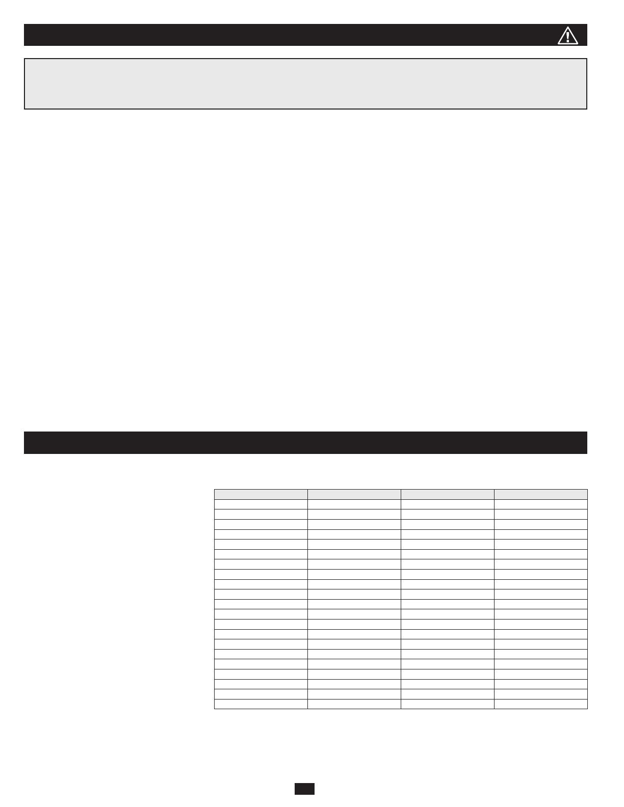
Available SmartRack Enclosures
Model # Rack Height Side Panels Shock Pallet
SR24UB 24U Yes No
SR24UBEXP 24U No No
SR24UBEXPSP1 24U No Yes
SR24UBSP1 24U Yes Ye s
SR42UB 42U Yes No
SR42UBCL 42U Yes No
SR42UBDP 42U Yes No
SR42UBDPWD 42U Yes No
SR42UBEXP 42U No No
SR42UBEXPND 42U No No
SR42UBEXPSP1 42U No Yes
SR42UBSP1 42U Yes Ye s
SR42UBWD 42U Yes No
SR42UBWDCL 42U Yes No
SR48UB 48U Yes No
SR48UBCL 48U Yes No
SR48UBDP 48U Yes No
SR48UBDPWD 48U Yes No
SR48UBEXP 48U No No
SR48UBEXPSP1 48U No Yes
SR48UBSP1 48U Yes Ye s
See the Specifications section for more information.
3
Feature Identification
Model SR42UB is shown. The other models have similar features, with the differences noted.
1
Roof Panel
2
Locking Split Rear Doors
3
Locking Side Panels(24Uenclosuresuse2sidepanelsinsteadof4.Sidepanelsarenotincludedwith“EXP”models.)
4
Cable Management Rails
5
Casters
A
and Levelers
B
6
Mounting Rails(Providehorizontalandverticalmountingpointsforequipment.)
7
Keys(Oneforthedoorsandoneforthesidepanels.)
8
Locking Reversible Front Door
Not Shown: Mounting hardware, documentation, shipping brackets and other shipping materials.
1
2
3
4
6
8
5
7
A
B
3
6
4
Enclosure Installation
Caution! Read All Instructions and Warnings Before Installation!
WARNING: The rack enclosure is extremely heavy. Do not attempt to unpack, move or install the enclosure without assistance. Until it has been properly
installed and stabilized, the enclosure is prone to tipping and could cause property damage and/or personal injury. Use extreme caution when handling the
enclosure and be sure to follow all handling and installation instructions. Do not attempt to install equipment without first stabilizing the enclosure.
Preparation
Theenclosuremustbeinstalledinastructurallysoundareawithalevelfloorthatisabletobeartheweightoftheenclosure,alltheequipmentthatwillbeinstalledinthe
enclosureandanyotherenclosuresand/orequipmentthatwillbeinstallednearby.Beforeunpackingtheenclosure,youshouldtransporttheshippingcontainercloserto
thefinalinstallationlocationtominimizethedistanceyouwillneedtomovetheunitaftertheprotectivepackaginghasbeenremoved.Ifyouplantostoretheenclosure
foranextendedperiodbeforeinstallation,followtheinstructionsintheStorage and Service section.
Youneedseveraltools(user-supplied):
• 13mmOpen-endWrench
• 18mmOpen-endWrench
• UtilityBlade
• Carpenter'sLevel
• Phillips-headScrewdriver
• 5/32"AllenWrench
Youalsoneedthefollowinghardware(included):
• (60)Phillips-headMountingScrews(M6x5/8")
• (60)CageNuts(M6)
• (60)NylonCupWashers
Unpacking
NOTE: If the enclosure is an “SP1” model with a shock pallet, follow the special unpacking instructions attached to the shipping container instead of the
unpacking instructions in this section. All warnings still apply.
1
Confirmthattheshippingcontainerisuprightandstable,thenuseautilitybladetocuttheshrink-wrap
securingthecornerprotectors.Applytheutilitybladedirectlyoverthecornerprotectorstopreventthe
utilitybladefromscratchingtheenclosureorcuttingtheheavyprotectiveplasticbagbeneaththeshrink-
wrap. WARNING: Do not scratch the enclosure or cut the heavy plastic bag beneath the shrink-wrap.
Do not push or pull the enclosure while unpacking.
2
Removethecornerprotectors.Saveallpackingmaterials(includingthepallet)forlateruseunless
youarecertaintheywillnotberequired.Thepackingmaterialsarerecyclable.
3
Removetheheavyplasticbagsurroundingtheenclosure.Examinetheenclosureforanydamageorloose
parts. Confirm that all parts are present. If anything is missing or damaged, contact Tripp Lite for
assistance.Donotattempttousetheenclosureifithasbeendamaged.
1
2
3
5
Enclosure Installation
Unpacking (continued)
4
Usethekeytoopentheenclosure'sdoorsandlocatethe2shippingbrackets
A
that attach the enclosure to
theshippingpallet.Thebracketsarelocatedinsidetheenclosure.Note: The keys are attached to the front of
the enclosure.
5
Usea13mmopen-endwrenchtoremovetheshippingbrackets.Beextremelycareful,astheenclosure
couldshiftunexpectedlyafterbracketremoval.Savethebracketsandbrackethardwareforlateruse.
6
Positionatleastonepersonatthefrontoftheenclosureandonepersonattherearoftheenclosure.Slowly
pushtheenclosuretowardthebackoftheshippingpalletuntilallfourcastersgoovertheedgeofthe
pallet and touch the floor. WARNING: Use at least one assistant when removing the enclosure from
the pallet. Be extremely careful when moving the enclosure.
Placement
1
Usethecasterstomovetheenclosureforashortdistanceoveralevel,smooth,stablesurfacebypushingit
fromthefrontorrear(notthesidepanels).Donotattempttorolltheenclosureoverlongdistances.The
enclosureshouldbemovedclosetoitsinstallationlocationinsideitsshippingcontainerbeforeitis
unpacked.(Useaforkliftorpalletjacktomovetheshippingcontainer.)WARNING: Do not push or pull
the enclosure at the side panels or pull the enclosure toward you.
Ifrequired,theenclosurecanbeliftedbyattaching4user-suppliedM8diametereyeboltstothethreaded
holesneartheuppercornersoftheenclosureframe.UsesteelboltswithanISOstrengthratingof8.8or
higher.The4boltscansupporttheweightoftheenclosureandupto1000lb(450kg)ofinstalled
equipment.WARNING: Only experienced equipment operators should attempt to lift the enclosure.
Use appropriate equipment and follow all applicable safety procedures and regulations.
A
4
5
6
1
6
Enclosure Installation
Leveling
WARNING: Level the enclosure before attempting to install equipment. The casters are not designed to provide long-term support for the enclosure. Use the
levelers to provide long-term support. Install the enclosure in a structurally sound area with a level floor that is able to bear the weight of the enclosure, all
equipment that will be installed in the enclosure and any other enclosures and/or equipment that will be installed nearby.
1
Aftertheenclosurehasbeenmovedtotheinstallationlocation,useacarpenter'sleveltochecktheslopeof
the floor. If the floor slopes more than 1%, choose an alternate installation site.
2
Usean18mmopen-endwrenchtolowereachleveler
A
untilitreachesthefloor.(Thereare4levelers,
2atthefrontand2attherear.)Makesureeachlevelercontactsthefloorsolidly.Note: Lower a leveler by
turning it clockwise; raise a leveler by turning it counter-clockwise.
3
Afterloweringeachleveler,usethecarpenter'sleveltoconfirmthattheenclosureislevelinalldirections.
Adjustthelevelersasrequireduntiltheenclosureislevel.
4
(Optional)Ifyouwishtoprovideanadditionalmeasureofstability,youcanattachthe2shippingbrackets,
usingthehardwarethatattachedtheenclosuretotheshippingpallet.Usea13mmopen-endwrenchto
connectthebracketstotheouter
A
or inner
B
bracketmountingpointsoftheenclosure.Attachthe
bracketstosecuremountingpointsinthefloorusinguser-suppliedhardwareorTrippLite'sSmartRack
Bolt-DownKit(Part#SR331).
Ground Connection
Allthepartsoftheenclosurearegroundedtotheframeoftheenclosure.Usetheenclosure'sfrontorrear
threaded grounding point
A
andanM6screw(included)toconnecttheframeoftheenclosuredirectlytoyour
facility'searthgroundconnectionwithan8AWG(3.264mm)wire.Routethegroundwireundertheenclosure's
frame to ensure unhindered door operation. WARNING: Attach each enclosure to earth ground separately.
Do not use the enclosure without an earth ground connection.
EARTH
GROUND
FLOOR
1
2
3
A
B
4
A
A
7
Enclosure Configuration
Adding or Removing Front and Rear Doors
WARNING: Do not attempt to add or remove doors without assistance.
Removing Door
1
Disconnectthedoor'sgroundwire.
2
Openthedooruntilitisperpendicular(90degrees)tothefrontoftheenclosure.
3
Lift the door from the hinges and remove it from the enclosure.
To Reinstall Door, Reverse Steps 1-3
(Optional)Iftheenclosureisjoinedtoanotherenclosure,turnthedoorbacktowardtheenclosureasyou
lift it from the hinges.
Reversing Front Door
WARNING: Do not attempt to reverse the front door without assistance.
1
Remove the screw connecting the ground wire to the inside of the door.
2
Remove the 2 screws connecting the door handle to the door. Remove the door handle.
90°
1
2
3
1
2
8
Enclosure Configuration
Reversing Front Door (continued)
3
Remove the screw and washer from the rear of the door handle and remove the latching mechanism. Rotate
thelatchwashercounter-clockwise90degreesandreversethelatchsoitpointsintheoppositedirection,
thenusethescrewandwashertore-attachthelatchtotherearofthedoorhandle.
4
Removethedoorbyfollowingthestepsintheprevioussection.
5
Removethedoorhingesfromtheenclosure,rotatethem180degreesandattachthemontheoppositeside
of the enclosure. Note: The alternate door hinge attachment points have plastic plugs in the screw holes.
Remove the plugs and insert them in the original door hinge attachment points.
6
Unscrew the 2 hinge mechanisms from the hinge openings inside the door, then reattach each of them using
the set of screw holes immediately opposite their original position.
7
Rotatethedoor180degreesandreinstallitontheenclosure.Remembertoconnectthegroundwiretothe
inside of the door, using the attachment point nearest the hinge at the top of the door. The attachment point
ismarkedwiththegroundconnectionsymbol: .
8
Reinstall the door handle.
3
4
5
7
6
8
9
Enclosure Configuration
Adding or Removing Roof Panel
WARNING: Do not attempt to use the roof panel for weight-bearing purposes other than those explicitly described and approved by Tripp Lite. Do not attempt
to add or remove the roof panel without assistance.
Removing Roof Panel
1
Pullthe2pinsneartherearoftheroofpanel.Whileholdingthepins,pushtheroofpanelupward.
2
Removetheroofpaneltabs
A
from the roof panel attachment slots
B
in the enclosure frame.
3
Lift the roof panel from the enclosure.
To Reinstall Roof Panel, Reverse Steps 1-3
Adding or Removing Side Panels
Removing Side Panel
1
Openthelatchbyslidingitdownward.
2
Tilt the top of the panel away from the enclosure.
2
1
1
2
1
2
3
A
B
10
Adding or Removing Side Panels (continued)
3
Liftthepanelawayfromthebracethatsupportsit.
To Reinstall Side Panel, Reverse Steps 1-3
Enclosure Configuration
Adjusting Mounting Rails and Cable Management Rails
WARNING: Do not attempt to adjust rails without assistance. Do not attempt to adjust rails while equipment is installed in the enclosure. Do not attempt to use
rails without screws installed (6 per rail).
The4mountingrailsarepre-installedtoaccommodateequipmentwithamountingdepthof30inches(762mm).Donotadjustthemountingrailsunlessyourequipment
requiresadifferentmountingdepth.Thefrontandrearsetsofrailscanbeadjustedindependentlyin¼-inch(6mm)incrementsformountingdepthsbetween4inches
(101.6mm)and42inches(1066.8mm).
1
Eachrailisconnectedtotheenclosurewith6screws-1pairattheupperbeam
A
, 1 pair at the middle
beam
B
and1pairatthelowerbeam
C
.
2
Removethescrewsfasteningeachoftherearmountingrailstotheenclosure.(Ifadjustmentofthefront
railsisrequired,youcanalsoremovethescrewsfromthefrontrails.)
3
Slide the mounting rails to the desired depth and reattach them using the screws you removed in Step 2.
Therailattachmentpointsarenumbered
A
to help you align each pair of rails at the same depth.
The depth of the 2 cable management rails can be adjusted using the same method.
4 5 6 3 4 5 6 7 8 9
0 1 2 3 4 5 6
8
4 5 6 5 6 7 8 9 0 1 2 3 4 5 6
0 1 2 3 4 5 6 7 8 9 0 1 2 3
5
3
A
B
C
1
2
3
A
11
Enclosure Configuration
Combining (Baying) Enclosures
WARNING: Combining enclosures is not a substitute for stabilizing the enclosures. Each enclosure in a bay of combined enclosures requires the same stabilizing
measures as a standalone enclosure.
1
Arrangetheenclosuresinthecorrectpositionforbaying.
2
Eachenclosureincludes4bayingbrackets
A
thatcorrespondtobayingconnectionpoints
B
on the
adjoiningenclosure.Thebayingconnectionpointsalreadycontainscrews.Removethescrewfromeach
bayingconnectionpointintheadjoiningenclosure.
3
Loosenthescrewineachbayingbracketandturneachbracket90degreestowardtheadjoiningenclosure,
aligningeachbracketwiththecorrespondingbayingconnectionpointontheadjoiningenclosure.
4
Connecteachbrackettotheadjoiningenclosureusingthescrewsyouremovedinstep2,butdonot
tightenthescrewscompletely.Adjustthepositionoftheenclosuresasneeded.Ifyouwantthecentersof
theenclosurestobe24inches(61cm)apart/29.9inches(76cm)fortheSR42UBWD,usetheoutsidehole
ofthebracket
C
.Ifyouwantthecenterstobe60cm(23.6inches)apart/75cm(29.5inches)forthe
SR42UBWD,usethemiddleholeofthebracket
D
.Afterconnectingallbracketsandconfirmingthatthe
enclosuresdonotneedfurtheradjustment,tightenallscrews.
Note: You may wish to remove the doors from the enclosures before combining them. Reinstalling the doors
afterward is optional. Remove the interior side panels before baying enclosures if you wish to enable access
between enclosures.
Equipment Installation
WARNING: Do not install equipment until you have stabilized the enclosure. Install heavier equipment first and install it toward the bottom of the enclosure.
Install equipment starting from the bottom of the enclosure and proceeding toward the top of the enclosure - never the reverse. If using sliding equipment rails,
be careful when extending the rails. Do not extend more than one set of sliding equipment rails at one time. Avoid extending sliding equipment rails near the top
of the enclosure.
Note: The square holes at the middle of each rack unit are numbered and also include a small notch to aid identification. A single rack unit includes the space occupied
by the numbered hole and the holes directly above and below.
90°
24
25
26
27
28
29
23
22
21
20
19
18
24
25
26
27
28
29
23
22
21
20
19
18
24
24
2
1 Rack Unit
3
4
2
1
C
D
A
B
12
Equipment Installation
Installing or Removing Cage Nuts
WARNING: The flanges of the cage nuts should engage the sides of the square opening in the rail, not the top and bottom. Follow the instructions in your
equipment documentation to ensure proper installation of your equipment.
Installing Cage Nuts
1
Locatethenumberedsquareopeningsinthemountingrailswhereyouplantoinstallyourequipment.You
willinstallcagenuts(included)intothesquareopeningsinordertoprovideanattachmentpointforthe
mountingscrews(included).Note: Consult your equipment documentation to determine how many cage
nuts will be required and where they will need to be installed.
2
Fromtheinsideofthemountingrail,insertoneoftheflangesofthecagenutthroughthesquareopening.
Pressitagainstthesideofthesquareopening.Eachflangeshouldengageonesideofthesquareopening,
notthetoporbottom.
3
Compressthecagenutatthesidesslightlytoallowtheremainingflangetofitthroughthesquareopening.
Whenthecagenutisproperlyinstalled,bothflangeswillprotrudethroughthesquareopeningandwillbe
visibleontheoutersurfaceofthemountingrail.Repeatsteps1-3untilallrequiredcagenutsareinstalled.
4
Afterinstallingtherequiredcagenuts,usetheincludedmountingscrewsandcupwasherstosecureyour
equipmenttotherackrail.Placethecupwashersbetweenthescrewsandtheequipmentmountingbrackets.
Note: Your equipment may also include mounting hardware. Read the mounting instructions that came with
your equipment before installing your equipment.
To Remove Cage Nuts, Reverse Steps 1-3
Note: You may wish to use a cage nut tool (user-supplied) to aid cage nut installation and removal.
20
19
18
22
21
20
19
18
22
21
20
19
18
22
21
20
19
18
22
21
1
2
3
4
13
Specifications
Load Capacity* Unit Dimensions Shipping Dimensions
Model Static Rolling Height Width Depth Weight Height Width Depth Weight
SR24UB 3000 lb
(1363 kg)
2250 lb
(1022 kg)
47.25 in
(1200 mm)
23.63 in
(600 mm)
43 in
(1092 mm)
190 lb
(86 kg)
51.4 in
(1306 mm)
26 in
(650 mm)
45 in
(1140 mm)
232 lb
(105 kg)
SR24UBEXP 3000 lb
(1363 kg)
2250 lb
(1022 kg)
47.25 in
(1200 mm)
23.63 in
(600 mm)
43 in
(1092 mm)
145 lb
(66 kg)
51.4 in
(1306 mm)
26 in
(650 mm)
45 in
(1140 mm)
187 lb
(85 kg)
SR24UBSP1 3000 lb
(1363 kg)
2250 lb
(1022 kg)
47.25 in
(1200 mm)
23.63 in
(600 mm)
43 in
(1092 mm)
190 lb
(86 kg)
51.4 in
(1306 mm)
28 in
(705 mm)
47 in
(1194 mm)
240 lb
(109 kg)
SR24UBEXPSP1 3000 lb
(1363 kg)
2250 lb
(1022 kg)
47.25 in
(1200 mm)
23.63 in
(600 mm)
43 in
(1092 mm)
145 lb
(66 kg)
51.4 in
(1306 mm)
28 in
(705 mm)
47 in
(1194 mm)
195 lb
(88 kg)
SR42UB 3000 lb
(1363 kg)
2250 lb
(1022 kg)
78.5 in
(1994 mm)
23.63 in
(600 mm)
43 in
(1092 mm)
286 lb
(130 kg)
85 in
(2149 mm)
26 in
(650 mm)
45 in
(1140 mm)
328 lb
(149 kg)
SR42UBCL 3000 lb
(1363 kg)
2250 lb
(1022 kg)
78.5 in
(1994 mm)
23.63 in
(600 mm)
43 in
(1092 mm)
305 lb
(138 kg)
85 in
(2149 mm)
26 in
(650 mm)
45 in
(1140 mm)
347 lb
(157 kg)
SR42UBDP 3000 lb
(1363 kg)
2250 lb
(1022 kg)
78.5 in
(1994 mm)
23.63 in
(600 mm)
47.3 in
(1200 mm)
315 lb
(143 kg)
85 in
(2149 mm)
26 in
(650 mm)
45 in
(1143 mm)
367 lb
(167 kg)
SR42UBDPWD 3000 lb
(1363 kg)
2250 lb
(1022 kg)
78.5 in
(1994 mm)
29.53 in
(750 mm)
47.3 in
(1200 mm)
342 lb
(155 kg)
85 in
(2149 mm)
26 in
(660 mm)
45 in
(1143 mm)
404 lb
(183 kg)
SR42UBEXP 3000 lb
(1363 kg)
2250 lb
(1022 kg)
78.5 in
(1994 mm)
23.63 in
(600 mm)
43 in
(1092 mm)
209 lb
(95 kg)
85 in
(2149 mm)
26 in
(650 mm)
45 in
(1140 mm)
251 lb
(114 kg)
SR42UBEXPND 3000 lb
(1363 kg)
2250 lb
(1022 kg)
78.5 in
(2261 mm)
23.63 in
(600 mm)
43 in
(1092 mm)
161 lb
(73.03 kg)
84 in
(2133.6 mm)
28 in
(711.2 mm)
47 in
(1193.8 mm)
211 lb
(95.7 kg)
SR42UBEXPSP1 3000 lb
(1363 kg)
2250 lb
(1022 kg)
78.5 in
(1994 mm)
23.63 in
(600 mm)
43 in
(1092 mm)
203 lb
(92 kg)
84 in
(2146 mm)
28 in
(705 mm)
47 in
(1194 mm)
253 lb
(115 kg)
SR42UBSP1 3000 lb
(1363 kg)
2250 lb
(1022 kg)
78.5 in
(1994 mm)
23.63 in
(600 mm)
43 in
(1092 mm)
286 lb
(130 kg)
84 in
(2146 mm)
28 in
(705 mm)
47 in
(1194 mm)
336 lb
(152 kg)
SR42UBWD 3000 lb
(1363 kg)
2250 lb
(1022 kg)
78.5 in
(1994 mm)
29.53 in
(750 mm)
43 in
(1092 mm)
313 lb
(142 kg)
85 in
(2149 mm)
26 in
(660 mm)
45 in
(1140 mm)
365 lb
(166 kg)
SR42UBWDCL 3000 lb
(1363 kg)
2250 lb
(1022 kg)
78.5 in
(1994 mm)
29.53 in
(750 mm)
43 in
(1092 mm)
304 lb
(138 kg)
85 in
(2149 mm)
26 in
(660 mm)
45 in
(1140 mm)
346 lb
(157 kg)
SR48UB 3000 lb
(1363 kg)
2250 lb
(1022 kg)
89 in
(2261 mm)
23.63 in
(600 mm)
43 in
(1092 mm)
315 lb
(143 kg)
95 in
(2416 mm)
26 in
(650 mm)
45 in
(1140 mm)
357 lb
(162 kg)
SR48UBCL 3000 lb
(1363 kg)
2250 lb
(1022 kg)
89 in
(2261 mm)
23.63 in
(600 mm)
43 in
(1092 mm)
334 lb
(151 kg)
95 in
(2416 mm)
26 in
(650 mm)
45 in
(1140 mm)
376 lb
(171 kg)
SR48UBDPWD 3000 lb
(1363 kg)
2250 lb
(1022 kg)
89 in
(2261 mm)
29.53 in
(750 mm)
47.3 in
(1200 mm)
378 lb
(171.5 kg)
26 in
(660 mm)
45 in
(1143 mm)
53 in
(1340 mm)
440 lb
(200 kg)
SR48UBEXP 3000 lb
(1363 kg)
2250 lb
(1022 kg)
89 in
(2261 mm)
23.63 in
(600 mm)
43 in
(1092 mm)
225 lb
(102 kg)
95 in
(2416 mm)
26 in
(650 mm)
45 in
(1140 mm)
267 lb
(121 kg)
SR48UBEXPSP1 3000 lb
(1363 kg)
2250 lb
(1022 kg)
89 in
(2261 mm)
23.63 in
(600 mm)
43 in
(1092 mm)
225 lb
(102 kg)
95 in
(2416 mm)
28 in
(705 mm)
47 in
(1194 mm)
213 lb
(96.6 kg)
SR48UBSP1 3000 lb
(1363 kg)
2250 lb
(1022 kg)
89 in
(2261 mm)
23.63 in
(600 mm)
43 in
(1092 mm)
315 lb
(143 kg)
95 in
(2416 mm)
26 in
(660 mm)
45 in
(1143 mm)
365 lb
(166 kg)
SR48UBWD 3000 lb
(1363 kg)
2250 lb
(1022 kg)
89 in
(2261 mm)
29.53 in
(750 mm)
43 in
(1092 mm)
343 lb
(156 kg)
95 in
(2416 mm)
26 in
(660 mm)
45 in
(1140 mm)
395 lb
(179 kg)
*“SP1”modelsincludeashockpalletthatallowstheenclosuretobeshippedwithpre-installedequipment.Themaximumshippingcapacityis1250lb(568kg),includingtheweightoftheenclosureandthe
pre-installedequipment.
Storage and Service
Storage
Theenclosureshouldbestoredinacontrolledindoorenvironment,awayfrommoisture,temperatureextremes,flammableliquidsandgasses,conductivecontaminants,
dustanddirectsunlight.Storetheenclosureinitsoriginalshippingcontainerifpossible.
Service
YourTrippLiteproductiscoveredbythewarrantydescribedinthismanual.AvarietyofExtendedWarrantyandOn-SiteServiceProgramsarealsoavailablefrom
TrippLite.Formoreinformationonservice,visitwww.tripplite.com/support.Beforereturningyourproductforservice,followthesesteps:
1.Reviewtheinstallationandoperationproceduresinthismanualtoinsurethattheserviceproblemdoesnotoriginatefromamisreadingoftheinstructions.
2.Iftheproblemcontinues,donotcontactorreturntheproducttothedealer.Instead,visitwww.tripplite.com/support.
3.Iftheproblemrequiresservice,visitwww.tripplite.com/supportandclicktheProductReturnslink.FromhereyoucanrequestaReturnedMaterialAuthorization
(RMA)number,whichisrequiredforservice.Thissimpleon-lineformwillaskforyourunit’smodelandserialnumbers,alongwithothergeneralpurchaser
information.TheRMAnumber,alongwithshippinginstructionswillbeemailedtoyou.Anydamages(direct,indirect,specialorconsequential)totheproduct
incurredduringshipmenttoTrippLiteoranauthorizedTrippLiteservicecenterisnotcoveredunderwarranty.ProductsshippedtoTrippLiteoranauthorizedTripp
Liteservicecentermusthavetransportationchargesprepaid.MarktheRMAnumberontheoutsideofthepackage.Iftheproductiswithinitswarrantyperiod,enclose
acopyofyoursalesreceipt.ReturntheproductforserviceusinganinsuredcarriertotheaddressgiventoyouwhenyourequesttheRMA.
14
Warranty and Warranty Registration
5-Year Limited Warranty
Seller warrants this product, if used in accordance with all applicable instructions, to be free from original defects in material and workmanship for a period of 5 years from the date of initial purchase. If the
product should prove defective in material or workmanship within that period, Seller will repair or replace the product, in its sole discretion.
THIS WARRANTY DOES NOT APPLY TO NORMAL WEAR OR TO DAMAGE RESULTING FROM ACCIDENT, MISUSE, ABUSE OR NEGLECT. SELLER MAKES NO EXPRESS WARRANTIES OTHER
THAN THE WARRANTY EXPRESSLY SET FORTH HEREIN. EXCEPT TO THE EXTENT PROHIBITED BY APPLICABLE LAW, ALL IMPLIED WARRANTIES, INCLUDING ALL WARRANTIES OF
MERCHANTABILITY OR FITNESS, ARE LIMITED IN DURATION TO THE WARRANTY PERIOD SET FORTH ABOVE; AND THIS WARRANTY EXPRESSLY EXCLUDES ALL INCIDENTAL AND
CONSEQUENTIAL DAMAGES. (Some states do not allow limitations on how long an implied warranty lasts, and some states do not allow the exclusion or limitation of incidental or consequential damages,
so the above limitations or exclusions may not apply to you. This warranty gives you specific legal rights, and you may have other rights which vary from jurisdiction to jurisdiction).
WARNING: The individual user should take care to determine prior to use whether this device is suitable, adequate or safe for the use intended. Since individual applications are subject to great variation, the
manufacturer makes no representation or warranty as to the suitability or fitness of these devices for any specific application.
Warranty Registration
Visit www.tripplite.com/warranty today to register the warranty for your new Tripp Lite product. You'll be automatically entered into a drawing for a chance to win a FREE Tripp Lite product!*
* No purchase necessary. Void where prohibited. Some restrictions apply. See Web site for details.
Tripp Lite follows a policy of continuous improvement. Product specifications are subject to change without notice.
Note on Labeling
This symbol is used on the product: Ground Connection
201008139 • 932723-EN
1111 W. 35th Street, Chicago, IL 60609 USA
www.tripplite.com/support
44
201008139 • 932723-FR
1111 W. 35th Street, Chicago, IL 60609 USA
www.tripplite.com/support
  • Page 1 1
  • Page 2 2
  • Page 3 3
  • Page 4 4
  • Page 5 5
  • Page 6 6
  • Page 7 7
  • Page 8 8
  • Page 9 9
  • Page 10 10
  • Page 11 11
  • Page 12 12
  • Page 13 13
  • Page 14 14
  • Page 15 15
  • Page 16 16
  • Page 17 17
  • Page 18 18
  • Page 19 19
  • Page 20 20
  • Page 21 21
  • Page 22 22
  • Page 23 23
  • Page 24 24
  • Page 25 25
  • Page 26 26
  • Page 27 27
  • Page 28 28
  • Page 29 29
  • Page 30 30
  • Page 31 31
  • Page 32 32
  • Page 33 33
  • Page 34 34
  • Page 35 35
  • Page 36 36
  • Page 37 37
  • Page 38 38
  • Page 39 39
  • Page 40 40
  • Page 41 41
  • Page 42 42
  • Page 43 43
  • Page 44 44

Tripp Lite SmartRack Owner's manual

Category
Racks
Type
Owner's manual

Ask a question and I''ll find the answer in the document

Finding information in a document is now easier with AI