Page is loading ...

OPERATOR'S MANUAL
MANUEL de L'UTILISATEUR
MANUAL del OPERADOR
TO REDUCE THE RISK OF INJURY, USER MUST READ AND UNDERSTAND OPERATOR'S
MANUAL.
AFIN DE RÉDUIRE LE RISQUE DE BLESSURES, L'UTILISATEUR DOIT LIRE ET BIEN
COMPRENDRE LE MANUEL DE L'UTILISATEUR.
PARA REDUCIR EL RIESGO DE LESIONES, EL USUARIO DEBE LEER Y ENTENDER EL
MANUAL DEL OPERADOR.
DIGITAL MULTIMETER (DMM)
MULTIMÈTRE NUMÉRIQUE (DMM)
MULTÍMETRO DIGITAL (DMM)
Cat. No.
No de cat.
2217-20

2
3
IMPORTANT SAFETY INSTRUCTIONS
WARNING READ ALL SAFETY WARNINGS AND INSTRUCTIONS.
Failure to follow the warnings and instructions may result in electric shock, fi re and/or serious
injury, as well as instrument damage and/or damage to the equipment being tested.
Save these instructions - This operator’s manual contains important safety and operating
instructions for the MILWAUKEE Digital Multimeters (DMM). Before using, read this
operator’s manual and all labels on the Digital Multimeters.
DANGER
Never make measurement on a circuit in which voltage over 600V rms exists. Use only leads
rated 600V CATIII or better.
Do not apply more than the rated voltage, as marked on the DMM, between terminals or be-
tween any terminal and earth ground.
Do not attempt a current measurement when the open voltage is above the fuse protection
rating. Suspected open circuit voltage can be checked with voltage function.
Do not use the DMM to measure voltages in circuits that could be damaged by the DMM’s low
input impedance in Lo-Z function is approximately 4K.
Do not attempt to make measurement in the presence of fl ammable gases. Otherwise, the use
of the instrument may cause sparking, which can lead to an explosion.
Never attempt to use the instrument if its surface or your hand is wet.
Do not exceed the maximum allowable input of any measuring range.
Only test on unenergized circuits unless absolutely necessary.
Check tool functionality on a known circuit fi rst. Never assume tool is working. Assume circuits
are live until they can be proven de-energized.
Never open the Battery cover during a measurement.
Do not ground yourself while measuring. Avoid body contact with earthed or grounded sur-
faces such as pipes, radiators, ranges and refrigerators.
This instrument is to be used only in its intended applications or conditions. Otherwise, the
instrument's safety functions may not work, resulting in serious personal injury and instru-
ment damage.
To reduce the risk of injury from shock and arc blasts, always wear personal protective
equipment where live conductors are exposed.
WARNING
Never attempt to make measurement if any abnormal conditions, such as broken case and
exposed metal parts are found on the instrument.
Comply with local and national safety requirements when working in hazardous locations.
Keep fi ngers behind the guards and away from test lead tips during measurements.
Do not rotate the Rotary Dial while the test leads are being connected.
Never attempt a voltage measurement with the test lead inserted into the A input terminal.
Verify proper operation on a known source before use or taking action as a result of the in-
dication of the instrument.
Do not install substitute parts, replace fuse or make any modifi cation to the instrument. For
repair or re-calibration, return the tool to a factory Service/Sales Support Branch or authorized
service station.
Do not try to replace the batteries if the surface of the instrument is wet.
Disconnect all the cords and cables from the object under test and power off the instrument
before opening the Battery Cover for Battery replacement.
This tool is designed to be powered by 2-AA batteries properly inserted into the MILWAUKEE
Digital Multimeters. Do not attempt to use with any other voltage or power supply.
CAUTION
Set the Rotary Dial to an appropriate position before starting measurement.
Disconnect test leads from test points before changing Rotary Dial functions.
Never connect to a source of voltage with the Dial function in OFF// / / / / .
Firmly insert the test leads.
Do not expose the instrument to the direct sun, high temperature and humidity or dew fall.
Altitude 2000m or less. Appropriate operating temperature is within -10ºC and 50ºC.
Keep away from excess dust and water.
Be sure to power off the instrument after use. When the instrument will not be in use for a long
period, place it in storage after removing the batteries.
Use a cloth dipped in water or neutral detergent for cleaning the instrument. Do not use
abrasives or solvents.
WARNING
Install battery according to polarity (+ and –) diagrams.
Do not leave batteries within the reach of children.
Do not mix new and used batteries. Do not mix brands (or types within brands) of batteries.
Properly dispose of used batteries.
Do not incinerate or dismantle batteries.
Under abusive conditions, liquid may be ejected from the battery, avoid contact. If contact
accidentally occurs, fl ush with water. If liquid contacts eyes, additionally seek medical help.
Liquid ejected from the battery may cause irritation or burns.
Accuracy is specifi ed for 1 year after calibration, at
operating temperatures of 18°C to 28°C (64°F to
82°F), with relative humidity at 45 % to 85 %.
Maximum voltage between any terminal and
earth ground.... 600 V
Temperature ....
Operating: -10°C to 50°C (14°F to 122°F)
for Current measurements: -10°C to 40°C
(14°F to 104°F)
Storage: -40°C to 60 °C (-40°F to 140°F)
Temperature Coeffi cient .... 0.1 x (specifi ed
accuracy)/°C (<18°C or >28°C)
Operating Altitude.... 2,000 meters
IP Rating
(International Dust & Water Protection) .... IP54
Drop Test .... 1 Meter
Battery .... 2 AA, NEDA 15 A,IEC LR6
Battery Life .... Approx. 30 Hours all lights on.
Fuse .... 10A / 600V Fast-acting
Safety Compliances .... EN61010-1,
UL 61010-1, UL 61010-031 (Probes),
EN61010-031 (Probes),
IEC/EN 61010-1 2nd Edition for measurement
Category III, 600 V, Pollution Degree 2,
EMC EN61326-1
Certifi cations .... cULus, CE
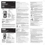
General Specifi cations FUNCTIONAL DESCRIPTION
1. Display
2. Range button
3. °F/°C button
4. Backlight button
5. V Terminal input
6. COM Terminal input
4
2
1
3
5
6
7
8
9
10
7. A Terminal input
8. Rotary Dial
9. Min/Max button
10. Hold button
11. Accessory bay
(on back, not shown)

4
5
ASSEMBLY
2. Unscrew and remove
battery door.
3. Insert two (2) AA
batteries, according to
the polarity marked in
the battery compartment
4. Close the battery door
and
tighten screw securely.
Symbology
Read Operator’s Manual
Double insulation
Risk of electric shock
Earth
Danger, Warning, or Caution -
Consult the operators manual for
additional safety information.
Battery compartment
European Conformity Mark
Underwriters Laboratories, Inc.,
United States and Canada
Cat III
Classifi cation of transient
overvoltages, based on nominal
line voltage to earth.
Fuse
Do not dispose of this product as
unsorted municipal waste.
WARNING
To avoid an electrical hazard,
turn the Rotary Dial to OFF and disconnect the
test leads before replacing batteries.
Dial Position Range Resolution Accuracy
Voltage AC
600mV/6V
60/600V
0.1mV/0.001V/
0.01V/0.1V
±(1.0% + 3 dgt) (45~500Hz)
±(2.0% + 3 dgt) (500~1000Hz)
Voltage DC 600mV/6/60/600V
0.1mV/0.001V/
0.01V/0.1V
±(0.5% + 2 dgt)
Lo-Z
Lo-Z
Low Input
Impedance
600V 0.1V ±(2.0% + 3 dgt) DC,AC : 45~500Hz
Hz
Hz
Hertz
99.99/999.9Hz
9.999/50.00kHz
0.01Hz/0.1Hz/
0.001kHz/0.01kHz
±(0.1% + 2 dgt)
Sensitivity: 10Vp-p
Resistance
600/6/60/600k
6M
40M
0.1/0.001k/0.01k/
0.1k/0.001M
±(1.0% + 5 dgt)
±(1.0% + 5 dgt)
0.01M ±(2.0% + 5 dgt)
Continuity
Cont Buzzer
0-600.0
Buzzer sounds at 30 or less
Capacitance
100F 0.1F
±(1.9% + 2 dgt)
1000F1F
Current AC
6A
10A
0.001A/0.01A ±(1.5% + 3 dgt) (45~500Hz)
Current DC
6A
10A
0.001A/0.01A ±(1.0% + 3 dgt)
Temperature
†
- 40ºC ~ 400ºC
-40ºF ~ 752ºF
0.1°C
0.2°F
±(1.0% + 10 dgt)
±(1.0% + 18 dgt)
Functions
†
Temperature Range, Resolution and Accuracy
are for the DMM. Temperature Probe may have
different specifi cations.
* These instruments are True-RMS sensing. All
voltage and current readings are True-RMS val-
ues.
* Input impedance: Voltage DC: 10M; Voltage AC:
10M // less than 100pF; Lo-z: 4k approximately
* Overload protection:
Voltage DC, voltage AC, Lo-Z Voltage and Herts:
AC/DC 720V for 10 second
Current DC & Current AC: AC/DC 20A for 10 sec.
Resistance, Continuity, Capacitance and Tem-
perature: AC/DC 600V for 10 second
* Maximum measurement time: 1 minute at 10A,
rest time 20 minutes minimum
* Minimum frquency measurement is 2Hz
* Minimum AC Current measurement is 0.040A
* For AC Voltage, AC Current and Lo-z:
Additional Accuracy by Crest Factor (C.F.): Add
1.0% for C.F. 1.4 ~ 2.0
Add 2.5% for C.F. 2.0 ~ 2.5
Add 4.0% for C.F. 2.5 ~ 3.0
Max. Crest Factor: 1.6 for 6600 ~ 5000 digits
2.0 for 5000 ~ 3000 digits
3.0 for 3000 ~ 0 digits
* Measurement accuracy of square wave and trun-
cated waveforms at 1kHz is unspecifi ed.
Loading/Changing the Batteries
Replace batteries when the Low Battery indicator
is displayed.
1. Turn Rotary Dial to OFF and disconnect the test
leads.
OPERATION
Before Use
Confi rm the Rotary Dial is set to the correct position,
the instrument is set to the correct measurement
mode, and the Data hold function is disabled. Oth-
erwise, desired measurement cannot be made.
LCD Backlight
The LCD backlight will turn off after about 10 min-
utes of inactivity. Press the backlight button to
turn the backlight on again.
Making a Measurement
AC Voltage
DANGER To avoid electrical shock:
Never make measurement on a circuit in
which voltage over AC600V exists.
Do not use with the Battery Cover removed.
Keep fi ngers behind the guards and away
from test lead tips during measurements.
CAUTION Readings may fl uctuate or
be infl uenced in noisy environment.
1. Set the Dial to position.
2. Connect the red test lead
to the V terminal and the
black test lead to the COM
terminal.
3. Connect the test leads to the
circuit under test. The read-
ing is displayed.
1. Set the Dial to
position.
2. Connect the red test lead
to the V terminal and the
black test lead to the COM
terminal.
3. Connect the red test lead
to the positive (+) side
and black test leads to the
negative (-) side of the cir-
cuit under test. The reading
is displayed. A reversed connection is indicated
as a negative value.
Lo-Z Low Input Impedance
Automatic voltage detection (AC or DC).
1. Set the Dial to Lo-Z position.
2. Connect the red test lead
to the V terminal and the
black test lead to the COM
terminal.
3. AC: Connect the test leads
to the circuit under test. The
reading is displayed.
DC: Connect the red test lead
to the positive (+) side and
black test leads to the negative (-) side of the circuit
under test. The reading is displayed. A reversed
connection is indicated as a negative value.
DANGER To avoid electrical shock:
Never make measurement on a circuit in
which voltage over DC600V exists. Do not use
with the Battery Cover removed. Keep fi ngers
behind the guards and away from test lead
tips during measurements.
DC Voltage
WARNING Only use Milwaukee test
leads with the MILWAUKEE DMM. Inspect test
leads for continuity before each use. Do not
use if the readings are high or noisy.
CAUTION Do not use the DMM to measure
voltages in circuits that could be damaged
by the DMM’s low input impedance less than
approximately 4k.

6
7
Resistance
1. Set the Dial to position.
2. Connect the red test lead to the
V terminal and the black test
lead to the COM terminal.
Confi rm “OL” is indicated on
the display, and then short-
circuit the tips of test leads to
make the indication zero.
3. Connect the test leads to the
both ends of the resistor under test.
4. The reading is displayed.
CAUTION After shorting the test leads,
the displayed value may not be zero due to the
resistance of test leads themselves.
Capacitance
1. Set the Dial to
position.
2. Use the Range button to se-
lect either 100F or 1000F.
3. Connect the red test lead
to the V terminal and the
black test lead to the COM
terminal.
4. Discharge capacitor.
5. Connect the test leads to the both ends of the
capacitor under test.
6. The reading is displayed.
AC Current
DANGER To reduce the risk of
electric shock for Resistance, Continuity,
and Capacitance measurements, never use
the DMM on an energized circuit. Make sure a
capacitor is fully discharged before touching
or attempting to make a measurement.
Do not use with the Battery Cover removed.
Hz Frequency
1. Set the Dial to Hz position.
2. Connect the red test lead to the
V terminal and the black test
lead to the COM terminal.
3. Connect the test leads to the
circuit under test. The reading
is displayed.
Resistance/Continuity/Capacitance
Measurements
DANGER To avoid electrical shock:
Never make measurement on a circuit in
which voltage over AC600V exists. Do not use
with the Battery Cover removed. Keep fi ngers
behind the guards and away from test lead
tips during measurements.
DANGER To avoid electrical shock:
Never make measurement on a circuit in
which voltage over AC600V exists.
Do not use with the Battery Cover removed.
Keep fi ngers behind the guards and away
from test lead tips during measurements.
1. Set the Dial to position.
2. Connect the red test lead
to the A terminal and the
black test lead to the COM
terminal.
3. Turn circuit power off, dis-
connect the circuit, connect
the test leads in series
with the circuit under test,
and then turn circuit power on. The reading is
displayed.
DC Current
Continuity
1. Set the Dial to position.
2. Connect the red test lead to
the V terminal and the black
test lead to the COM termi-
nal.
Confi rm “OL” is indicated on
the display, and then short-
circuit the tips of test leads to
make the indication zero. A
buzzer will sound.
3. Connect the test leads to the
both ends of the conductor
under test. If the resistance
under test is 30 or less, the
buzzer will sound.
1. Set the Dial to
position.
2. Connect the red test lead
to the A terminal and the
black test lead to the COM
terminal.
3. Turn circuit power off, dis-
connect the circuit, connect
the test leads in series
with the circuit under test,
and then turn circuit power on. The reading is
displayed.
WARNING
Never connect the Temperature Probe to an
energized circuit.
CAUTION
When the dial is set to , OL should be dis-
played. If anything else is displayed, some-
thing may be wrong with the DMM. Stop using
the DMM immediately.
Temperature
1. Set the Dial to position.
2. Connect the K-type Tempera-
ture Probe to the input termi-
nal. The positive (+) side of
Probe should be connected
to V.
3. Contact the probe sensor to
the object under test.
4. The reading is displayed.
CAUTION
The Data Hold readings of maximum / mini-
mum are released when the DMM enters Sleep
Mode.
Press MIN/MAX to step through the minimum (MIN
displayed), maximum (MAX displayed), and pres-
ent readings (both MAX and MIN are displayed).
To pause MIN MAX recording without erasing
stored values, press HOLD button the HOLD is
displayed.
To resume MIN MAX recording, press HOLD but-
ton again.
To exit and erase stored readings, press MAN/MAX
button for two seconds or change the dial.
Range Button
The DMM has both Manual and Autorange modes.
In the Autorange mode, the DMM selects the range
with the best resolution, and in the Manual Range
mode, you override Autorange and select the range
yourself. When you turn the DMM on, it defaults
to Autorange and AUTO is displayed. To enter the
Manual Range mode, press RANGE button, AUTO
disappears. In the Manual Range mode, press
RANGE button to increment the range. After the
highest range, the Meter wraps to the lowest range.
To exit Manual Range, press RANGE button for two
seconds or change the dial. The Meter returns to
Autorange and AUTO is displayed.
CAUTION
Pressing the MIN/MAX button without apply-
ing voltage disables the Auto-ranging func-
tion and fi xes the Range to 6mV. Connect the
test leads to the circuit under test and press
the MIN/MAX button after an appropriate
range is selected by Auto-ranging function.
°F / °C
To switch between Fahrenheit or Celsius, press
the °F / °C button.
Sleep Mode
The DMM is automatically powered off in about 20
min after the last Rotary Dial or button operation. To
reset, rotate the Rotary Dial to OFF. If the display
is still blank when a new dial setting is selected,
replace the batteries.
The DMM does use battery power in sleep mode.
Be sure to switch the tool to OFF to conserve bat-
tery power.
Over-fl ow indication
Any time the input exceeds the measuring range
“OL” or “-OL” is displayed.
Accessory Bay
To install an accessory, slide it into the accessory
bay on the back of the DMM. Follow the instructions
supplied with the accessory
Using Bar Graph Display
The bar graph is like the needle on an analog me-
ter, it updates much faster than the digital display.
The number of segments indicates the measured
value and is relative to the full-scale value of the
selected range.
HOLD Button
Data Hold Function - Freezes the value on the dis-
play. Press the HOLD button to freeze the reading.
The reading will be held regardless of subsequent
variation in input. HOLD is displayed with the read-
ing. To exit Data Hold mode, press the HOLD button
again or change the dial.
SMART HOLD: The meter will beep continuously
and the display will fl ash if the measured signal is 50
counts larger than the display reading. (However,
it can not detect across the AC and DC Voltage/
Current).
MIN/MAX Button
The MIN MAX recording mode captures the mini-
mum and maximum input values. When a new high
or low is detected, the DMM beeps.
Put the DMM in the desired measurement function
and range, then press MIN/MAX button to enter
MIN MAX mode, and present readings and MAX
MIN are displayed.

8
9
FIVE YEAR TOOL
LIMITED WARRANTY
MILWAUKEE Test & Measurement Products (includ-
ing bare tool, li-ion battery pack(s) and battery char-
ger but excluding alkaline batteries) are warranted
to the original purchaser only to be free from defects
in material and workmanship. Subject to certain
exceptions, MILWAUKEE will repair or replace
any part on this product which, after examination,
is determined by MILWAUKEE to be defective in
material or workmanship for a period of fi ve (5)
years* after the date of purchase. Return the Test
& Measurement tool and a copy of proof of purchase
to the nearest Milwaukee Electric Tool Corporation
- factory Service Center. This warranty does not
apply to damage that MILWAUKEE determines to
be from repairs made or attempted by anyone other
than MILWAUKEE authorized personnel, misuse,
alterations, abuse, normal wear and tear, lack of
maintenance, or accidents.
*The warranty period for the LITHIUM-ION battery
pack that ships with the Test & Measurement tool is
two (2) years from the date of purchase. *Alkaline
battery that ships with Test & Measurement tool is
separately warranted by the battery manufacturer.
*The warranty period for a NON-CONTACT VOLT-
AGE DETECTOR – 2201 20 is one (1) year from
the date of purchase.
Warranty Registration is not necessary to obtain
the applicable warranty on MILWAUKEE product.
The manufacturing date of the product will be used
to determine the warranty period if no proof of
purchase is provided at the time warranty service
is requested.
ACCEPTANCE OF THE EXCLUSIVE REPAIR AND
REPLACEMENT REMEDIES DESCRIBED HEREIN
IS A CONDITION OF THE CONTRACT FOR THE
PURCHASE OF EVERY MILWAUKEE PRODUCT.
IF YOU DO NOT AGREE TO THIS CONDITION,
YOU SHOULD NOT PURCHASE THE PRODUCT.
IN NO EVENT SHALL MILWAUKEE BE LIABLE FOR
ANY INCIDENTAL, SPECIAL, CONSEQUENTIAL
OR PUNITIVE DAMAGES, OR FOR ANY COSTS,
ATTORNEY FEES, EXPENSES, LOSSES OR DE-
LAYS ALLEGED TO BE AS A CONSEQUENCE OF
ANY DAMAGE TO, FAILURE OF, OR DEFECT IN
ANY PRODUCT INCLUDING, BUT NOT LIMITED
TO, ANY CLAIMS FOR LOSS OF PROFITS. THIS
WARRANTY IS EXCLUSIVE AND IN LIEU OF
ALL OTHER WARRANTIES OR CONDITIONS,
WRITTEN OR ORAL, EXPRESSED OR IMPLIED.
WITHOUT LIMITING THE GENERALITY OF THE
FOREGOING, MILWAUKEE DISCLAIMS ANY IM-
PLIED WARRANTY OF MERCHANTABILITY OR
FITNESS FOR A PARTICULAR USE OR PURPOSE,
AND ALL OTHER WARRANTIES.
This warranty applies to product sold in the U.S.A.,
Canada and Mexico only.
MAINTENANCE
WARNING To reduce the risk of per-
sonal injury and damage, never immerse
your tool in liquid or allow a liquid to fl ow
inside them.
WARNING To reduce the risk of injury,
always remove the batteries from the tool
before performing any maintenance. Never
disassemble the tool. Contact a MILWAUKEE
service facility for ALL repairs.
Cleaning
Clean dust and debris from the tool. Keep tool
handles clean, dry and free of oil or grease. Dirt
or moisture in the terminals can affect readings.
Use only mild soap and a damp cloth to clean the
tool since certain cleaning agents and solvents
are harmful to plastics and other insulated parts.
Some of these include gasoline, turpentine, lacquer
thinner, paint thinner, chlorinated cleaning solvents,
ammonia and household detergents containing
ammonia. Never use fl ammable or combustible
solvents around tools.
Repairs
For repairs, return the tool to the nearest service
center listed on the back cover of this operator's
manual.
Maintaining Tool
Keep your tool in good repair by adopting a regular
maintenance program. After one year, it is recom-
mended to return the tool to a MILWAUKEE service
facility for calibration.
If the tool does not start or operate at full power
with fully charged batteries, clean the contact in the
battery compartment. If the tool still does not work
properly, return the tool to a MILWAUKEE service
facility for repair.
ACCESSORIES
For a complete listing of accessories refer to your
MILWAUKEE Electric Tool catalog or go online to
www.milwaukeetool.com. To obtain a catalog, con-
tact your local distributor or a service center listed
on the back cover of this operator’s manual.
WARNING Always remove batteries
before changing or removing accessories. Only
use accessories specifi cally recommended for
this tool. Others may be hazardous.
RÈGLES IMPORTANTES DE SÉCURITÉ
DANGER
Ne jamais prendre une mesure sur un circuit dont la tension effi cace est supérieure à 600 V.
Utiliser uniquement des fi ls qui résistent à une tension d’au moins 600 V CAT III.
Ne pas appliquer plus que la tension nominale, indiquée sur le multimètre numérique, entre
les bornes ou entre une borne et une prise de terre.
Ne pas tenter de mesurer le courant lorsque la tension ouverte est supérieure à la valeur de
protection du fusible. Il est possible de vérifi er si un circuit comporte une tension ouverte au
moyen de la fonction « Tension ».
Ne pas utiliser le multimètre numérique pour mesurer la tension de circuits susceptibles
d’être endommagés par la faible impédance d’entrée de l’instrument (environ 4 k en fonc-
tion « Lo-Z »).
Ne pas tenter de prendre une mesure en présence de gaz infl ammables. L’utilisation de
l’instrument peut causer des étincelles, ce qui peut entraîner une explosion.
Ne jamais tenter d’utiliser l’instrument si sa surface est mouillée ou si vos mains le sont.
Ne pas excéder l’alimentation maximale permise de toute plage de mesure.
Effectuer uniquement des essais sur des circuits hors tension, à moins qu’il soit absolument
nécessaire de procéder autrement.
Vérifi er d’abord le fonctionnement de l’outil sur un circuit connu. Ne jamais tenir pour acquis
que l’outil fonctionne. Présumer que les circuits sont sous tension jusqu’à ce qu’il soit con-
fi rmé qu’ils sont hors tension.
Ne jamais ouvrir le couvercle des piles au moment de prendre une mesure.
Ne pas mettre l’instrument à la terre au moment de prendre une mesure. Éviter tout contact
avec des surfaces mises à la terre comme des tuyaux, des radiateurs, des cuisinières et des
réfrigérateurs.
Cet instrument doit être utilisé uniquement pour effectuer les applications pour lesquelles il
est conçu, et il doit fonctionner uniquement dans les conditions recommandées. Autrement,
il est possible que les fonctions de sécurité de l’instrument défaillent, ce qui peut entraîner
des blessures graves et endommager l’instrument.
Pour réduire le risque de blessures découlant d’une décharge ou de l’explosion d’un arc
électrique, porter de l’équipement de protection individuel au moment de travailler dans un
endroit renfermant des conducteurs sous tension et non protégés.
AVERTISSEMENT
Ne jamais tenter de prendre une mesure dans des conditions anormales par exemple, si le
boîtier de l’instrument est cassé et que des pièces métalliques sont exposées.
Respecter les exigences locales et nationales en matière de sécurité au moment de travailler
dans des environnements dangereux.
Garder les doigts derrière les protecteurs et à l’écart du bout des fi ls d’essai au moment de
prendre les mesures.
Ne pas tourner le cadran rotatif si les fi ls d’essai sont branchés.
Ne jamais tenter de mesurer la tension en insérant un fi l d’essai dans la borne d’entrée A.
S’assurer du bon fonctionnement de l’instrument sur une source d’alimentation connue avant
de l’utiliser ou d’agir en se fondant sur ce qu’il indique.
AVERTISSEMENT LIRE TOUS LES AVERTISSEMENTS ET TOUTES LES
INSTRUCTIONS. Ne pas suivre l’ensemble des avertissements et des instructions peut
entraîner une électrocution, un incendie ou des blessures graves, en plus d’endommager le
multimètre et l’équipement mis à l’essai.
Conserver ces instructions – Ce manuel contient des instructions importantes de sécurité et
de fonctionnement pour le multimètre numérique MILWAUKEE. Avant d’employer l’instrument,
lire le présent manuel d’utilisation ainsi que toutes les étiquettes se trouvant sur le multimètre
numérique.

24
MILWAUKEE ELECTRIC TOOL CORPORATION
13135 West Lisbon Road • Brookfi eld, Wisconsin, U.S.A. 53005
58-14-2219d4 6/09 Printed in China
UNITED STATES - MILWAUKEE Service
MILWAUKEE prides itself in producing a premium
quality product that is NOTHING BUT HEAVY DUTY
®
.
Your satisfaction with our products is very impor-
tant to us! If you encounter any problems with the
operation of this tool, or you would like to locate the
factory Service/Sales Support Branch or authorized
service station nearest you, please call...
Canada - Service MILWAUKEE
MILWAUKEE est fi er de proposer un produit de pre-
mière qualité NOTHING BUT HEAVY DUTY
®
. Votre satisfac-
tion est ce qui compte le plus!
En cas de problèmes d’utilisation de l’outil ou pour loca-
liser le centre de service/ventes ou le centre d’entretien
le plus proche, appelez le...
416.439.4181
fax: 416.439.6210
Milwaukee Electric Tool (Canada) Ltd
755 Progress Avenue
Scarborough, Ontario M1H 2W7
Notre réseau national de distributeurs agréés se
tient à votre disposition pour fournir l’aide technique,
l’outillage et les accessoires nécessaires. Composez
le 416.439.4181 pour obtenir les noms et adresses
des revendeurs les plus proches ou bien consultez la
section «Où acheter» sur notre site web à l’adresse
www.milwaukeetool.com
MEXICO - Soporte de Servicio
MILWAUKEE
1-800-SAWDUST
(1.800.729.3878)
Monday-Friday
7:00 AM - 6:30 PM
Central Time
or visit our website at
www.milwaukeetool.com
Additionally, we have a nationwide network of
authorized Distributors ready to assist you with
your tool and accessory needs. Check your “Yellow
Pages” phone directory under “Tools-Electric” for
the names & addresses of those nearest you or see
the 'Where To Buy' section of our website.
Contact our Corporate After Sales Service
Technical Support about ...
•Technical Questions
•Service/Repair Questions
•Warranty
call: 1-800-SAWDUST
fax: 1.800.638.9582
email: [email protected]
Register your tool online at
www.milwaukeetool.com and...
• receive important notifi cations regarding
your purchase
• ensure that your tool is protected under the
warranty
• become a HEAVY DUTY club member
For service information, use the 'Service Center
Search' icon found in the 'Parts & Service' section.
Herramientas Alerka
Dr. Andrade 140 Local B, Col. Doctores
Delegación Cuauhtemoc, México D.F.
Telefono sin costo 01 800 832 1949
www.ttigroupmexico.com
Adicionalmente, tenemos una red nacional de distribui-
dores autorizados listos para ayudarle con su herramienta
y sus accesorios. Por favor, llame al 01 800 832 1949 para
obtener los nombres y direcciones de los más cercanos
a usted, o consulte la sección ‘Where to buy’ (Dónde
comprar) de nuestro sitio web en
www.ttigroupmexico.com
Registre su herramienta en línea, en
www.ttigroupmexico.com y...
• reciba importantes avisos sobre su compra
• asegúrese de que su herramienta esté
protegida por la garantía
• conviértase en integrante de Heavy Duty
/