Yamaha HTR-4065 Owner's manual

Category
AV receivers
Type
Owner's manual

This manual is also suitable for

En 1
Check that the following accessories are supplied with the product.
The following cables (not supplied) are required to build the system described in this
document.
Speaker cables (depending on the number of speakers)
HDMI cable (x2)
Audio pin cable (x1)
Digital optical cable (x1)
(not required if your TV supports ARC [Audio Return Channel])
1 Preparation
Accessories
Remote control Batteries
(AAA, R03, UM-4) (x2)
Insert the batteries the right way round.
AM antenna FM antenna YPAO microphone
CD-ROM
(Owner’s Manual)
Safety Brochure Easy Setup Guide
The illustrations of the main unit and remote control used in this guide are of the HTR-5065 (U.S.A.
model), unless otherwise specified.
*The supplied FM antenna
varies depending on the
region of purchase.
Cables required for connections
Easy Setup Guide
English
AV Receiver
This document explains how to set up a 5.1- or 7.1-channel system
(HTR-5065 only) and play back surround sound from a BD/DVD on the unit.
To reduce the impact on natural resources, the Owners Manual for this product is
supplied on CD-ROM. For more information about this product, refer to the
Owners Manual on the supplied CD-ROM.
PDF versions of this guide and “Owners Manual” can be downloaded from the
following website.
http://download.yamaha.com/
HTR-5065_4065_esg_G.fm Page 1 Monday, January 23, 2012 2:24 PM
Black process 45.0° 240.0 LPI
2 En
Set up the speakers in the room using the following diagram as a reference.
For information on other speaker systems, refer to “Owner’s Manual”.
1 Front speaker (L)
2 Front speaker (R)
3 Center speaker
4 Surround speaker (L)
5 Surround speaker (R)
6 Surround back speaker (L)
7 Surround back speaker (R)
9 Subwoofer
2 Placing speakers
5.1-channel system
12
39
45
10° to 30°10° to 30°
7.1-channel system
(HTR-5065 only)
45
1
2
39
67
30 cm (1 ft) or more
10° to 30° 10° to 30°
HTR-5065_4065_esg_G.fm Page 2 Monday, January 23, 2012 2:24 PM
Black process 45.0° 240.0 LPI
En 3
Connecting speaker cables
Speaker cables have two wires. One is for connecting the
negative (–) terminals of the unit and the speaker, and the
other is for the positive (+) terminals. If the wires are
colored to prevent confusion, connect the black wire to
the negative and the other wire to the positive terminals.
a Remove approximately 10
mm (3/8”) of insulation
from the ends of the
speaker cable and twist
the bare wires of the cable
firmly together.
b Loosen the speaker terminal.
c Insert the bare wires of the cable into the gap on the side
(upper right or bottom left) of the terminal.
d Tighten the terminal.
Using a banana plug
(U.S.A. and China models
only)
a Tighten the speaker
terminal.
b Insert a banana plug into
the end of the terminal.
1
Connect the front speakers (1/2)
to the FRONT (//\) terminals.
2
Connect the center speaker (3) to the
CENTER terminal.
3 Connecting speakers/subwoofer
(U.S.A. model only)
Under its default settings, the unit is configured for 8-ohm
speakers. When connecting 6-ohm speakers, set the unit’s
speaker impedance to “6 Ω MIN”. For details, see “Setting the
speaker impedance” in “Owner’s Manual”.
(Except for U.S.A. model)
Use speakers with an impedance of at least 6 Ω.
Use a subwoofer equipped with built-in amplifier.
Before connecting the speakers, remove the unit’s power cable
from the AC wall outlet and turn off the subwoofer.
Ensure that the core wires of the speaker cable do not touch
each other or come into contact with the unit’s metal areas. This
may damage the unit or the speakers. If the speaker cables
short circuit, “Check SP Wires” will appear on the front display
when the unit is turned on.
FRONT
aa
b
d
c
– (black)
+ (red)
FRONT
a
b
Banana plug
FRONT CENTER SURROUND
OR OUT
P
B
Y
SUBWOOFER
SPEAKERS
12
3
45
9
The unit (rear)
FRONT CENTER SURROUND
OR OUT
P
B
Y
SUBWOOFER
SPEAKERS
12
3
45
9
The unit (rear)
HTR-5065_4065_esg_G.fm Page 3 Monday, January 23, 2012 2:24 PM
Black process 45.0° 240.0 LPI
4 En
3
Connect the surround speakers
(4/5) to the SURROUND (//\)
terminals.
4
Connect the subwoofer (9) to the
SUBWOOFER jack.
Connect the surround back speakers
(6/7) to the SURROUND BACK (//\)
terminals.
FRONT CENTER SURROUND
OR OUT
P
B
Y
SUBWOOFER
SPEAKERS
12
3
45
9
The unit (rear)
FRONT CENTER SURROUND
OR OUT
P
B
Y
SUBWOOFER
SPEAKERS
12
3
45
9
Audio pin cable
The unit (rear)
For 7.1-channel system (HTR-5065 only)
FRONT CENTER SURROUND
SINGLE
SURROUND BACK/BI AMP
/ZONE B
OR OUT
P
B
Y
SUBWOOFER
SPEAKERS
1
67
2
3
45
9
The unit (rear)
HTR-5065_4065_esg_G.fm Page 4 Monday, January 23, 2012 2:24 PM
Black process 45.0° 240.0 LPI
En 5
4 Connecting external devices
FRONT CENTER SURROUND
SINGLE
SURROUND BACK/BI AMP
/ZONE B
AV 1
AV
2
AV 3
AV 5
AV 6
OPTICAL COAXIAL COAXIAL OPTICAL
(
TV
)
COMPONENT
VIDEO
COMPONENT
VIDEO
P
B
Y
VIDEO
AV
MONITOR OUT
OUT
AUDIO
AV 4
P
R
P
B
Y
P
R
HDMI 1
(
BD/DVD
)
HDMI 2
HDMI 3
HDMI 4
NETWORK
HDMI
OUT
ARC
FM
ANTENNA
AM
SUBWOOFER
SPEAKERS
INFO
MEMORY
PRESET
FM AM
TUNING
CONTROL
TV
BD
DVD
NET
RADIO
INPUT
SCENE
YPAO MIC
PHONES
SILENT
CINEMA
STRAIGHT
VIDEO
DIRECT
iPod/iPhone/iPad
5V 2.1A
AUDIO
VIDEO
VOLUME
AUX USB
TONE
PROGRAM
HDMIOPTICAL
HDMI
HDMI
HDMI
OUT
ARC
HDMI HDMI
HDMI
O
AV 4
OPTICAL
(TV)
O
HDMI 1
(
BD/DVD
)
a
c
b
d
TV
Audio out
(optical)
HDMI in HDMI out
BD/DVD player
HDMI OUT
jack
HDMI 1 jack
AV 4 (OPTICAL) jack
The unit (rear)
To an AC wall
outlet
Turn on the unit
The unit (front)
1
Connect external devices to the unit.
a Connect a BD/DVD player to the unit with an HDMI
cable.
If the BD/DVD player is currently connected to the
TV directly with an HDMI cable, disconnect the
cable from the TV and connect it to this unit.
b Connect a TV to the unit with the other HDMI cable.
c Connect a TV to the unit with a digital optical cable.
This connection is required to play back TV audio
on the unit. This connection is not required if your
TV supports ARC (Audio Return Channel).
d Connect the power cable to an AC wall outlet.
For information on how to connect radio antennas or other
external devices, see “PREPARATIONS” in “Owner’s Manual”.
2
Turn on the unit, the TV and the BD/DVD
player.
3
Use the TV remote control to change the
TV input to video from the unit.
The connections are complete. Proceed to the next
page to optimize the speaker settings.
By connecting a TV to the unit with an HDMI cable, you can
configure the unit’s settings with the menu displayed on the TV. In
addition, you can select the on-screen menu language from English
(default), French, German, Spanish, Russian and Chinese. For
details, refer to “Owner’s Manual”. In this guide, illustrations of
English menu screens are used as examples.
HTR-5065_4065_esg_G.fm Page 5 Monday, January 23, 2012 2:24 PM
Black process 45.0° 240.0 LPI
6 En
The Yamaha Parametric room Acoustic Optimizer (YPAO) function detects speaker connections, measures the
distances from them to your listening position(s), and then automatically optimizes the speaker settings, such as
volume balance and acoustic parameters, to suit your room.
Preparing for YPAO
5
Optimizing the speaker settings automatically (YPAO)
SCENE
RETURN
VOLUME
ENHANCER
DIRECT
HDMI
AV
FM
INFO
MEMORY
AM
PRESET
MOVIE MUSIC
BD
DV
D
MUTE
ENTER
TV
TV VOL TV CH
TOP
MENU
POP-UP
MENU
DISPLAY
SOURCE
RECEIVER
CODE SET
OPTION
SETUP
TUNING
STRAIGHT
SUR. DECODE
INPUT
MUTE
9 0
10
ENT
56 87
12
34
MODE
TV
NET
RADIO
TUNER
1 2
3
NET
USB
V-AUX
6
A
B
ZONE
5
4
1 2 3 4
SLEEP
AUDIO
SC
EN
E
RETURN
V
O
LUME
NHANCE
D
IREC
T
HDMI
AV
FM
I
NF
O
M
EM
O
RY
AM
P
RESET
M
O
VIE
MUSI
C
BD
DV
D
M
UT
E
TV
TV
V
O
L
TV
C
H
T
O
P
MEN
U
POP-U
P
MEN
U
DISPL
AY
SOU
R
CE
R
E
C
EIVER
CO
DE
S
ET
O
PTI
O
N
TUNING
S
TRAI
GH
T
S
UR
.
D
E
CO
D
E
INP
U
T
MUTE
9
0
10
EN
T
6
5
8
7
1
2
3
4
MOD
E
TV
NET
RADI
O
TUNE
R
1
2
3
NE
T
US
B
V-AU
X
6
A
B
Z
O
NE
5
4
1
2
3
4
S
LEE
P
AUDI
O
Cursor keys
ENTER
SETUP
During the measuring process, test tones are output at high volume. Ensure that the test
tones do not frighten small children. Also, refrain from using this function at night when it
may be a nuisance to others.
During the measuring process, you cannot adjust the volume.
During the measuring process, keep the room as quiet as possible.
Do not connect headphones.
Do not stand between the speakers and the YPAO microphone during the measurement
process (about 3 minutes).
Move to the corner of the room or leave the room.
VOLUME HIGH CUT
CROSSOVER/
MIN MAXMIN MAX
The unit (front)
Place the YPAO microphone at your
listening position (same height as your
ears). We recommend the use of a
tripod as a microphone stand. You can
use the tripod screws to fix the
microphone in place.
YPAO microphone
Listening position
Ear height
Turn on the subwoofer and set
the volume to half. If the
crossover frequency is
adjustable, set it to maximum.
1
Connect the YPAO microphone to the
YPAO MIC jack on the front panel.
The following screen appears.
To cancel the operation, disconnect the YPAO microphone, or
use the cursor keys to select “Exit” and press ENTER, before
starting the measurement.
2
To start the measurement, press SETUP.
The measurement will start in 10 seconds.
The following screen appears on the TV when
the measurement finishes.
Auto Setup
Start
Exit
Press SETUP key
to Start
Power Amp Assign
Basic
VOL.
SW
L
SL
C
SR
R
[SETUP]:Start
Auto Setup
Start
Exit
Measurement
Finished
Result
3 / 2 / 0.1 ch
3.0 / 10.5 m
-3.0 / +10.0 dB
VOL.
SW
L
SL
C
SR
R
Finished
HTR-5065_4065_esg_G.fm Page 6 Monday, January 23, 2012 2:24 PM
Black process 45.0° 240.0 LPI
En 7
If any error message (such as E-1) or warning message (such
as W-2) appears, see “Error messages” or “Warning
messages” in “Owner’s Manual”.
If the warning message “W-1:Out of Phase” appears, see “If
“W-1:Out of Phase” appears”.
3
Use the cursor keys (e/r) to select
SAVE” (Save) and press ENTER.
4
Disconnect the YPAO microphone from the
unit.
This completes optimization of the speaker settings.
Follow the procedure below to check the speaker
connections.
Depending on the type of speakers or room
environment, this message may appear even if the
speakers are connected correctly.
a Check for the blinking of the front display’s indicator to
identify the problem speaker.
b Check the cable connections (+/-) of the problem
speaker.
If the speaker is connected correctly:
You can save the current settings.
Proceed to step 3.
If the speaker is connected incorrectly:
Turn off the unit, reconnect the speaker cable, and then
try YPAO measurement again.
The YPAO microphone is sensitive to heat, so should not be
placed anywhere where it could be exposed to direct sunlight or
high temperatures (such as on top of AV equipment).
Auto Setup
Start
Exit
Measurement
Finished
Result
3 / 2 / 0.1 ch
3.0 / 10.5 m
-3.0 / +10.0 dB
SAVE
VOL.
SW
L
SL
C
SR
R
>SaveCancel
If “W-1:Out of Phase” appears
Warning
message
Auto Setup
Start
Exit
Measurement
Finished
Result
3 / 2 / 0.1 ch
3.0 / 10.5 m
-3.0 / +10.0 dB
W-1:Out of Phase
VOL.
SW
L
SL
C
SR
R
W-1:PHASE
Problem speaker (blinks)
HTR-5065_4065_esg_G.fm Page 7 Monday, January 23, 2012 2:24 PM
Black process 45.0° 240.0 LPI
8 En
Now let’s play back a BD/DVD.
We recommend playing back multichannel audio
(5.1-channel or more) to feel surround sound produced
by the unit.
1
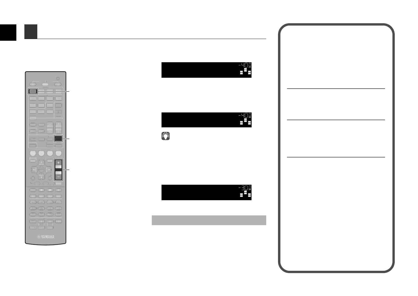
Press HDMI 1 to select “HDMI 1” as the
input source.
2
Start playback on the BD/DVD player.
3
Press STRAIGHT repeatedly to select
STRAIGHT”.
When “STRAIGHT” (straight decode) is enabled, each
speaker produces each channel audio signal directly (without
sound field processing).
(HTR-5065 only)
If you play back 5.1-channel audio on the 7.1-channel system,
no sounds will be heard from the surround back speakers.
4
Press VOLUME to adjust the volume.
This completes the basic setup procedure.
Sound is only being output from the front speakers
during multichannel audio playback
Check the digital audio output setting on the BD/DVD
player.
It may be set to 2-channel output (such as PCM).
No sound is coming from a specific speaker
See “Troubleshooting” in “Owner’s Manual”.
6 Playing back a BD/DVD
SCENE
RETURN
VOLUME
ENHANCER
DIRECT
HDMI
AV
FM
INFO
MEMORY
AM
PRESET
MOVIE MUSIC
BD
DV
D
MUTE
ENTER
TV
TV VOL TV CH
TOP
MENU
POP-UP
MENU
DISPLAY
SOURCE
RECEIVER
CODE SET
OPTION
SETUP
TUNING
STRAIGHT
SUR. DECODE
INPUT
MUTE
9 0
10
ENT
56 87
12
34
MODE
TV
NET
RADIO
TUNER
1 2
3
NET
USB
V-AUX
6
A
B
ZONE
5
4
1 2 3 4
SLEEP
AUDIO
SC
EN
E
R
ETURN
NHANCE
D
IREC
T
HDMI
AV
FM
I
NF
O
M
EM
O
RY
AM
P
RESET
M
O
VIE
MUSI
C
BD
DV
D
M
UT
E
ENTER
TV
TV
V
O
L
TV
C
H
T
O
P
MEN
U
POP-U
P
MEN
U
D
I
S
PL
AY
SOU
R
CE
R
E
C
EIVER
CO
DE
S
ET
O
PTI
O
N
S
ETUP
TUNING
S
UR
.
D
E
CO
D
E
INP
U
T
MUTE
9
0
10
EN
T
6
5
8
7
1
2
3
4
MOD
E
TV
NET
RADI
O
TUNE
R
1
2
3
NE
T
US
B
V-AU
X
6
A
B
Z
O
NE
5
4
2
3
4
S
LEE
P
AUDI
O
HDMI 1
STRAIGHT
VOLUME
If surround sound is not working
SW
C
L
SL SR
R
HDMI1
VOL.
SW
C
L
SL SR
R
VOL.
STRAIGHT
SW
C
L
SL SR
R
Volume -30.0dB
VOL.
Many more features!
The unit has various other functions.
Please refer to “Owner’s Manual” on the supplied
CD-ROM to help you get the most out of the unit.
Connecting other playback
devices
Connect audio devices (such as CD player),
game consoles, camcorders, and many others.
Selecting the sound mode
Select the desired sound program (CINEMA
DSP) or surround decoder suitable for movies,
music, games, sports programs, and other uses.
Playing back from iPod
By using a USB cable supplied with iPod, you
can enjoy iPod music on the unit.
Listening to FM/AM radio
Playing back music stored on
a USB storage device
Playing back the network
contents
Selecting the input source and
favorite settings at once
For more information, see “What you can do
with the unit”.
HTR-5065_4065_esg_G.fm Page 8 Monday, January 23, 2012 2:24 PM
Black process 45.0° 240.0 LPI
4 Sv
3
Anslut surroundhögtalarna (4/5) till
kontakterna som är märkta SURROUND BACK
(//\).
4
Anslut subwoofern (9) till SUBWOOFER-
uttaget.
Anslut de bakre surroundhögtalarna (6/7)
till SURROUND BACK (//\)-kontakterna.
FRONT CENTER SURROUND
OR OUT
P
B
Y
SUBWOOFER
SPEAKERS
12
3
45
9
Receivern (baksida)
FRONT CENTER SURROUND
OR OUT
P
B
Y
SUBWOOFER
SPEAKERS
12
3
45
9
Ljudstiftkabel
Receivern (baksida)
r 7.1-kanalsystem (gäller endast HTR-5065)
FRONT CENTER SURROUND
SINGLE
SURROUND BACK/BI AMP
/ZONE B
OR OUT
P
B
Y
SUBWOOFER
SPEAKERS
1
67
2
3
45
9
Receivern (baksida)
HTR-5065_4065_esg_G.fm Page 4 Thursday, February 9, 2012 4:20 PM
2 It2 It
Posizionare i diffusori nella stanza utilizzando il seguente schema come riferimento.
Per ulteriori informazioni su altri sistemi di diffusori, consultare il "Manuale di istruzioni".
1 Diffusore anteriore (S)
2 Diffusore anteriore (D)
3 Diffusore centrale
4 Diffusore surround (S)
5 Diffusore surround (D)
6 Diffusore posteriore surround (S)
7 Diffusore posteriore surround (D)
9 Subwoofer
2 Posizionamento dei diffusori
Sistema a 5.1 canali
12
39
45
da 10° a 30°da 10° a 30°
Sistema a 7.1 canali
(solo per il modello HTR-5065)
45
1
2
39
67
30 cm o più
da 10° a 30° da 10° a 30°
HTR-5065_4065_esg_G.fm Page 2 Tuesday, February 7, 2012 2:15 PM
© 2012 Yamaha Corporation Printed in Malaysia ZA52710
HTR-5065_4065_esg_G_cover4.fm Page 2 Wednesday, January 18, 2012 1:31 PM
Black process 45.0° 240.0 LPI
1 / 1

Yamaha HTR-4065 Owner's manual

Category
AV receivers
Type
Owner's manual
This manual is also suitable for

Ask a question and I''ll find the answer in the document

Finding information in a document is now easier with AI

Ask the document