Page is loading ...

© 2008 • All rights reserved. 3
HDR44 4x4 High Defi nition Video Router
Safety
NOTE: This equipment has been tested and found to comply with the limits for a Class B digital device, pursuant to part 15 of the
FCC Rules. These limits are designed to provide reasonable protection against harmful interference in a residential installation.
This equipment generates, uses and can radiate radio frequency energy and, if not in-stalled and used in accordance with the
instructions, may cause harmful interference to radio communications. However, there is no guarantee that interference will not
occur in a particular installation.
If this equipment does cause harmful interference to radio or television reception, which can be determined by turning the
equipment off and on, the user is encouraged to try to correct the interference by one or more of the following measures:
Reorient or relocate the receiving antenna.
Increase the separation between the equipment and receiver.
Connect the equipment into an outlet on a circuit different from that to which the receiver is connected.
Consult the dealer or an experienced radio/TV technician for help.
CAUTION: Changes or modifi cations not expressly approved by ATON could void the user’s authority to operate the equipment
Caring For the HDR44
Clean only with a dry soft cloth.
It is important to properly care for your HDR44 HD Video Router. Follow these guidelines to ensure your device is preserved and
protected.
Do not expose the HDR44 to rain, liquids or moisture for an extended period of time.
Do not expose the HDR44 to temperature extremes.
Do not place any objects on top of the HDR44 to prevent chassis damage.
Operating Temperatures & Environments
Operating Temperature: 32-104°F (0-40° C)
Humidity: 0-90%
Precautions
Always exercise care when operating the HDR44 HD. Video Router
Do not install near any heat sources such as radiators, heat registers, stoves, or other apparatus (including
amplifiers) that produce heat.
In the unlikely event that smoke, abnormal noise, or strange odor is present, immediately power the HDR44
off. Please report the problem to your dealer immediately.
Never attempt to disassemble the HDR44. You will lose any product warranty on the unit.
Package Contents
HDR44 4x4 High Defi nition Video Router
R44IRM Slimline Remote Control
2 Meter RJ-45 to RJ-45 Cable
3.5mm Stereo Interconnect Cable
User/Installation Manual
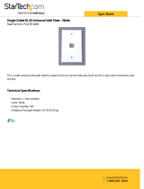
ATON HDR44 Accessories
R44WP HD Receive Wall Plate
R44IRM Slimline IR Remote
REKT Rack Ear Kit
Note: For more information and purchase options, visit our website at:
www.atonhome.com.
•
•
•
•
•
•
•
•
•
•
•
•
•

4 ©2008 • All rights reserved.
HDR44 4x4 High Defi nition Video Router
Contents
Safety Information ...................................................................... 1
1. Introduction .............................................................................. 5
Features ........................................................................................ 6
Front Panel Call-Out ..................................................................... 7
Rear Panel .................................................................................... 8
2. System Design Overview ...................................................... 9
Applications .................................................................................. 9
Basic 4 Source 4 Zone System ................................................... 9
Expanded 4 Source 8 Zone System .......................................... 10
3. Connections ........................................................................... 11
ALL IR OUT .................................................................................. 11
EXTERNAL IR INPUT ................................................................... 12
SOURCE IR EMITTER OUTPUTS ................................................. 13
COMPONENT VIDEO INPUTS ...................................................... 14
ANALOG AUDIO INPUTS ............................................................. 15
SPDIF DIGITAL INPUT ................................................................. 15
WALLPLATE OUTPUT CONNECTIONS ........................................ 16
EXPANSION CONNECTIONS ...................................................... 21
CONTROL LOOP ........................................................................... 22
COMPONENT VIDEO OUTPUT ..................................................... 22
ANALOG AUDIO INPUTS ............................................................. 23
SPDIF DIGITAL OUTPUTS ............................................................ 23
4. Settings & Operation .......................................................... 24
IR Remote Control ...................................................................... 24
Using The R44IRM ..................................................................... 25
Individual Zone Control .............................................................. 25
System-wide Zone Control ......................................................... 25
5. Troubleshooting ..................................................................... 26
Appendix A: R44WP HD Receive Wall Plate ..................... 28
Appendix B: Specifi cations ................................................... 29
Appendix C: Rack Ear Kit ........................................................ 31
Limited Warranty .......................................................... Back Page

© 2008 • All rights reserved. 5
HDR44 4x4 High Defi nition Video Router
1. Introduction
Modern Convenience
The HDR44 4 Source, 4 Zone High Defi nition Video Router and R44WP HD Receive Wall Plates
provide the ability to view up to 4 different video sources in up to 8 separate areas (with ad-
ditional HDR44 Chassis) of the home for total fl exibility and convenience. No need to have
multiple audio/video systems in different areas, just select a source from your IR remote, sit
back and enjoy!
Simple Control
ATON’s R44IRM Slimline IR System Remote (included) provides control of zone and source
selection, etc. Use the R44IRM or download discrete IR codes from the ATON website (www.
atonhome.com) to learn source and zone commands into 3rd party remotes for even greater
control options of the HDR44.
Simple, Logical Installation
The HDR44 uses CAT-5 cabling, making it reliable and easy to install. Any video source with digi-
tal or analog outputs can be connected directly to the HDR44. R44WP HD Receive Wall Plates
are then connected to the HDR44 using 2 CAT-5 cables, while sources are connected with and
component video cables and digital and analog RCA connectors.
Figure 1-1: HDR44
Figure 1-2: R44WP

6 ©2008 • All rights reserved.
HDR44 4x4 High Defi nition Video Router
HDR44 Features
4 Source, 4 Zone High Defi nition Video Router
Expandable up to 8 Zones With Additional HDR44 Chassis
Passes all Hi-Def Formats including 1080p
Sends Component Video, Analog Audio, SPDIF Digital Audio &
Two-Way IR Using 2 CAT-5 Cables
500 Foot Range (HDR44 to R44 Wall Plate)
Zone Specifi c IR Control using R44WP Wall Plates or System-
wide Control Using External IR Input
Source-Specifi c IR Routing Capabilities
No PC Software Required For Setup
Compact Single Rack Space Design
Rack Mountable – Optional Rack Ear Kit Available (REKT)
2 Year Limited Warranty
R44WP Features
Receives All Video and Audio from the HDR44 Via 2 Cat-5 Cables
Outputs HD Video, Analog, and Digital Audio to Each Zone
IR Receiver Input on the Front and Back for Control of HDR44
and Connected Sources
IR Emitter Loop Output for Control of In-Room Audio/Video
Sources
Single-Gang Decora
®
(Faceplate Included)
Includes AIR1B Surface Mount IR Receiver
•
•
•
•
•
•
•
•
•
•
•
•
•
•
•
•
•

© 2008 • All rights reserved. 7
HDR44 4x4 High Defi nition Video Router
Front Panel
The front panel of the HDR44 is populated simply by Zone Source LED’s and a single Power
LED. Figure 1-3 and Table 1-1 provide descriptions and locations of Front Panel indicators.
1 2 3 4 5
Figure 1-3: HDR44 Front Panel
Indicator/Button Function LED
1
Zone 1 Source LED Indicates Source 1-4 Status Blue
2
Zone 2 Source LED Indicates Source 1-4 Status Blue
3
Zone 3 Source LED Indicates Source 1-4 Status Blue
4
Zone 4 Source LED Indicates Source 1-4 Status Blue
5
Power LED Indicates Power ON/OFF Status Red
Table 1-1: Front Panel

8 ©2008 • All rights reserved.
HDR44 4x4 High Defi nition Video Router
Rear Panel
The Rear Panel of the HDR44 has connections for IR, Expansion I/O, Analog and Digital Audio,
Component Video, and Zone Wallplate Outputs . Figure 1-4 and Table 1-2 provide description
and location of Rear Panel connections.
11 10 9 7
6542 31
8
Figure 1-4 : HDR44 Rear Panel
Connector Function
1
EXT. IR In 3.5mm Stereo Mini Jack Connector for
Use w/ ATON IR Receivers
2
IR ALL Out 3.5mm Mono Mini Jack Connector for
Use With ATON IR Emitters or AIB4 IR
Distribution Block
3
Source IR Outputs 3.5mm Mono Mini Jack Connectors for
Use w/ ATON IR Emitters
4
Digital Audio Inputs Coaxial Digital Audio Cable Connections
5
Component Video Inputs Component Video Cable Connections
6
Wallplate Outputs RJ45 (T568A Pinout) for Use w/ R44WP
HD Receive Wallplates
7
Component Loop Outputs Component Video Cable Connections to
Additional Routers
8
SPDIF Loop Outputs Coaxial Digital Audio Cable Connections
to Additional Routers
9
Audio Inputs RCA Audio Cable Connections
10
Control Loop RJ45 Connection to Additional Routers
11
Power Connection 120 VAC-60Hz Wall Outlet Cord
Table 1-2: Rear Panel

© 2008 • All rights reserved. 9
HDR44 4x4 High Defi nition Video Router
2. System Design Overview
Applications
There are two typical system applications when installing the HDR44. These options can be
combined throughout a system depending on the design of the application:
Basic 4 Source, 4 Zone System
Expanded 4 Source, 5-8 Zone System
Basic 4 Zone, 4 Source System
Figure 2-1 shows a basic HDR44 system with four sources and four zones. The system is
comprised of a HDR44 HD Video Router, 4 Video Sources, 4 R44WP HD Receive Wall Plates,
optional AV Receivers in two zones and ATON Storm Series Speakers. This confi guration pro-
vides video and audio from each source into each zone as well as control of each source from
each zone.
P
R
P
B
Y
SPDIF
SPDIF
IR
OUT
OUT
IR
IN
IN
L
R
P
R
P
B
Y
SPDIF
SPDIF
IR
OUT
OUT
IR
IN
IN
L
R
P
R
P
B
Y
SPDIF
SPDIF
IR
OUT
OUT
IR
IN
IN
L
R
P
R
P
B
Y
SPDIF
SPDIF
IR
OUT
OUT
IR
IN
IN
L
R
Figure 2-1: Basic System
1.
2.

10 ©2008 • All rights reserved.
HDR44 4x4 High Defi nition Video Router
Expanded 4 Source, 5-8 Zone System
Figure 2-2 shows an expanded system with four sources and eight zones. The system is com-
prised of two HDR44 HD Video Routers, 4 Video Sources, 8 R44WP HD Receive Wall Plates,
optional AV Receivers in 4 zones, and ATON Storm Series Speakers. This confi guration provides
video and audio from each source into each zone as well as control of each source from each
zone.
P
R
P
B
Y
SPDIF
SPDIF
IR
OUT
OUT
IRIN
L
R
P
R
P
B
Y
SPDIF
SPDIF
IR
OUT
OUT
IR
IN
IN
L
R
P
R
P
B
Y
SPDIF
SPDIF
IR
OUT
OUT
IR
IN
IN
L
R
P
R
P
B
Y
SPDIF
SPDIF
IR
OUT
OUT
IR
IN
IN
L
R
P
R
P
B
Y
SPDIF
SPDIF
IR
OUT
OUT
IRIN
L
R
P
R
P
B
Y
SPDIF
SPDIF
IR
OUT
OUT
IR
IN
IN
L
R
P
R
P
B
Y
SPDIF
SPDIF
IR
OUT
OUT
IR
IN
IN
L
R
P
R
P
B
Y
SPDIF
SPDIF
IR
OUT
OUT
IR
IN
IN
L
R
Figure 2-2: Expanded System

© 2008 • All rights reserved. 11
HDR44 4x4 High Defi nition Video Router
3. Connections
The HDR44 is part of an integrated system that requires the use of other ATON components.
Depending on the system design, these components may include:
R44IRM Slimline IR Remote Control
R44WP HD Receive Wall Plates - one per zone
HDR44 Router - for systems containing from 5 to 8 zones.
ATON IR Receivers and Emitters
This section describes the connectivity between these various ATON components and the video
source components that comprise the system. Each HDR44 system is unique, and not all con-
nections will be made in every installation.
Important Safety Note: Make sure that the HDR44 is unplugged before
making any connections.
ALL IR OUT
The ALL IR PORT is constantly active and passes IR information regardless of the source
selected. This is useful for sources that may need control no matter which source is active, such
as an HD TV Receiver, or for applications utilizing an expanded IR network including IR Distribu-
tion devices such as ATON’s AIB4 Amplifi ed IR Connection Block as shown below.
AIB4
Amplified
Connecting Block
3.5mm
Mono
Interconnect
Cable
HDR44
Figure 3-1: All OUT
•
•
•
•

12 ©2008 • All rights reserved.
HDR44 4x4 High Defi nition Video Router
EXT. IR INPUT
ATON multi-room applications can utilize the EXT.IR IN port of a single HDR44 chassis for IR
control from a Universal/Learning RF-to-IR remote control. Use a 3.5mm mono interconnect
cable to connect between an IR OUT port of a third party RF to IR converter and the EXT. IR IN
port of the HDR44.
Note: This application is designed to work with a single chassis HDR44 system. For more
advanced multi-chassis applications utilizing the EXT IR INPUT, please visit our website at
www.atonhome.com.
PWR
USB
STATUS
RF DATA
+12VDC
GND
SIGNAL
SENSE
3.5mm
Mono
Interconnect
Cable
HDR44
RF-to-IR
Converter
Figure 3-2: EXT. IR INPUT
HDR44
ATON AIR5
IR Receiver
Figure 3-3: ATON AIR5 to EXT. IR INPUT
Multiple zones of a single HDR44 chassis can be controlled when utilizing an ATON AIR5 IR
Receiver connected to the HDR44 EXT. IR INPUT.
Note: This application is designed to work with a single chassis HDR44 system. For more
advanced multi-chassis applications utilizing the EXT IR INPUT, please visit our website at
www.atonhome.com.

© 2008 • All rights reserved. 13
HDR44 4x4 High Defi nition Video Router
SOURCE IR OUTPUTS
Connect a standard IR Emitter (ATON AIE2, for example) from the Source IR OUT port on the
rear of the HDR44 to the IR receiver on the front of the audio/video source (see Figure 3-4).
The four source IR outputs are source specifi c. For examle, IR port “1” must be mounted to the
video source connected to “Component Video Input 1”. For sources that have an IR Input port
on the back of the unit, use a 3.5mm to 3.5mm mono interconnect cable instead .
IR Emitter
BluRay Disc™
HDR44
3.5mm mono
interconnect cable
Figure 3-4 SOURCE IR OUTPUTS
Component Video Connections
P
R
P
B
Y
SPDIF
SPDIF
IR
OUT
OUT
IR IN
L
R
BluRay Disc™
HDR44
R44WP
HD Video Display
IR Receiver
Figure 3-5: Component Video Signal Chain

14 ©2008 • All rights reserved.
HDR44 4x4 High Defi nition Video Router
COMPONENT VIDEO INPUTS
Use high-quality component video cables to make connections between video sources
and the HDR44’s inputs. Sources will typically be located near the HDR44 at the head-
end of the system. Component video outputs as well as audio outputs and IR will be
sent via Cat-5 cables from the head-end to R44WP HD Receive wall plates located
throughout the house. Use high-quality component video cables to connect to each
HD video display from the R44WP as well. See Figure 3-12 on page 17 for detailed
R44WP to HD video display connections.
Y
Pb
Video Source
Component Output
Component
Video Patch
Cables
Pr
Figure 3-6: COMPONENT VIDEO INPUTS
Source Audio Connections
P
R
P
B
Y
SPDIF
SPDIF
IR
OUT
OUT
IR
IN
IN
L
R
BluRay Disc™
HDR44
R44WP
HD Video Display
Audio Receiver
Digital Path
Analog Path
IR Receiver
Figure 3-7: HDR44 Audio Pathway

© 2008 • All rights reserved. 15
HDR44 4x4 High Defi nition Video Router
AUDIO INPUTS
The HDR44 supports a total of four System Sources which are available to all four zones and
can be sent to up to a total of eight zones using another HDR44 Router for system expansion.
There are two types of Source Inputs. Analog (RCA), and Digital Coaxial.
Analog AUDIO INPUTS
Use a Stereo RCA patch cable to connect a video source with analog outputs to the HDR44’s
Analog Audio Inputs as shown in Figure 3-8.
L
R
Source Analog Output
Stereo
RCA Patch
Cables
Figure 3-8: Analog AUDIO INPUTS
Note: If any or all connected video displays are designed to receive analog audio, be sure
to make these analog audio connections. The R44WP does not convert digital audio
inputs to analog audio or vice-versa.
SPDIF AUDIO INPUTS
Use a Digital Coaxial cable to connect a video source with a Digital Coaxial output to the
HDR44’s Source Input as shown in Figure 3-9. Digital Connections provide the best audio qual-
ity and should be used if available.
SPDIF
Audio Source
Digital Output
Digital Coax
Patch Cable
HDR44
Figure 3-9: SPDIF AUDIO INPUTS
Note: If any or all connected video displays are designed to receive digital audio, be sure
to make these digital audio connections. The R44WP does not convert analog audio
inputs to digital audio or vice-versa.

16 ©2008 • All rights reserved.
HDR44 4x4 High Defi nition Video Router
Wall Plate Connections
A R44WP HD Receive Wall Plate is required to connect video, audio, and IR to a zone. The
R44WP wall plate has component video, audio, and IR connections that connect to the Video
and Audio inputs of each zone’s HD Video Display. A run of (2) two Cat-5 Cables terminated to
T-568A standard, shown in Figure 3-11, is required between the HDR44 and the location des-
ignated for the R44WP. Connections between a source component and the HDR44 are detailed
in Figure 3-6 through Figure 3-9,while connections between the R44WP and the zone HD Video
Display are detailed in Figure 3-12.
RJ45 Cable
RJ45 Cable
R44WP
HDR44
Figure 3-10: Wall Plate Connections
1 2 3 4 5 6 7 8
12 34 56 78
GREEN/WHITE
GREEN
ORANGE/WHITE
BLUE
BLUE/WHITE
ORANGE
BROWN/WHITE
BROWN
Shown tab
down
Figure 3-11: T568A Wiring Standard

© 2008 • All rights reserved. 17
HDR44 4x4 High Defi nition Video Router
P
R
P
B
Y
SPDIF
SPDIF
IR
OUT
OUT
IR
IN
IN
L
R
P
R
P
B
Y
L
R
P
R
P
B
Y
P
R
P
B
Y
L
R
L
R
1
AUDIO
AUDIO
IR
IN
IN
R44WP
HD Video Display Audio and Video Inputs
2 3
1 2 3
COMPONENT VIDEO
COMPONENT VIDEO
DIGITAL
DIGITAL
COAX
COAX
OUT
Component
Video Cable
RCA Stereo
Cable
3.5mm Mono
Interconnect
Cable
HDMI
HDMI
Figure 3-12: R44WP to HD Video Display

18 ©2008 • All rights reserved.
HDR44 4x4 High Defi nition Video Router
P
R
P
B
Y
SPDIF
SPDIF
IR OUT
IR
IN
IN
L
R
P
R
P
B
Y
L
R
P
R
P
B
Y
P
R
P
B
Y
L
R
L
R
1
AUDIO
AUDIO
IR
IN
R44WP
HD Video Display Audio and Video Inputs
2 3
1 2 3
COMPONENT VIDEO
COMPONENT VIDEO
DIGITAL
DIGITAL
COAX
COAX
OUT
OUT
RCA Stereo
Patch Cable
HDMI
HDMI
Figure 3-13: R44WP to Analog Audio Input
P
R
P
B
Y
SPDIF
IR
OUT
OUT
IR IN
L
R
R44WP
DIGITAL
DIGITAL
COAX
COAX
Home Theater
Receiver
(Optional)
Figure 3-14: R44WP to Digital Coax Connector
Note: For applications where the SPDIF audio connection needs to be extended, install
one RG59 or RG6 Coaxial cable in the wall from the R44WP Wall Plate to the AV Receiver
location utilizing F connector to RCA adapters.

© 2008 • All rights reserved. 19
HDR44 4x4 High Defi nition Video Router
IR Connections
Front Panel IR Emitter Connection
Insert the 3.5mm plug of an IR emitter into the designated IR Out port of the R44WP and place
the emitter on the IR receive window of an in-room video source or display.
P
R
P
B
Y
SPDIFSPDIF
IR OUTOUT
IR ININ
L
R
R44WP
HD Video Display
IR Emitter
Figure 3-15: R44WP Front Panel IR Emitter Connection
Rear Panel IR Emitter Connection
Run a Cat-5 wire from the R44WP to the location of an in-room video source or AV Receiver.
Next, cut off the 3.5mm plug of an IR emitter and strip back the wire jacket to expose the wires.
Then, twist the bare ends of the IR emitter wires and splice them onto the appropriate conduc-
tors of the Cat-5 wire as shown in Figure 3-16
. Finally, connect the correct Cat-5 conductors to
the screw terminals of the R44WP.
IR OUT
GND
ATON AIE2
IR Emitter
to Source
R44WP
SPLICE
IR (White Stripe)
GND (Black)
GND (Brown)
IR (Blue/White)
Cat-5 Cable
Figure 3-16: R44WP Rear IR Output

20 ©2008 • All rights reserved.
HDR44 4x4 High Defi nition Video Router
Front Panel IR Receiver Connection
Connect an ATON IR Receiver to R44WP front panel IR Input connector as shown in Figure 3-17.
P
R
P
B
Y
SPDIF
SPDIF
IR
OUT
OUT
IR IN
L
R
R44WP
HD Video Display
IR Receiver
3.5mm mono
connector
Figure 3-17: R44WP Front Panel IR IN Connection
+12VDC
IR IN
AIR1 IR Receiver
R44WP
GND
SPLICE
IR (White)
GND (Black)
GND (Brown)
IR (Blue/White)
Cat-5 Cable
+12V (Red)
+12V (White/Green)
Figure 3-18: R44WP Rear Panel IR IN Connection
Run a Cat-5 wire from the R44WP to the IR Receiver location. Next, cut off the 3.5mm plug of
the IR Receiver and strip back the wire jacket to expose the conductor wires. Then, strip the
ends of the conductors and twist the bare ends of the IR Receiver wires to the appropriate con-
ductors of the Cat-5 wire as shown in Figure 3-18. Finally, connect the correct Cat-5 conductors
to the screw terminals of the R44WP.

© 2008 • All rights reserved. 21
HDR44 4x4 High Defi nition Video Router
Expansion Connections
System Expansion
The HDR44 is capable of supporting four sources in up to eight zones. The system may be
expanded by adding an additional HDR44.
P
R
P
B
Y
SPDIF
SPDIF
IR
OUT
OUT
IR
IN
IN
L
R
P
R
P
B
Y
SPDIF
SPDIF
IR
OUT
OUT
IR
IN
IN
L
R
P
R
P
B
Y
SPDIF
SPDIF
IR
OUT
OUT
IR
IN
IN
L
R
P
R
P
B
Y
SPDIF
SPDIF
IR
OUT
OUT
IR
IN
IN
L
R
P
R
P
B
Y
SPDIF
SPDIF
IR
OUT
OUT
IR
IN
IN
L
R
P
R
P
B
Y
SPDIF
SPDIF
IR
OUT
OUT
IR
IN
IN
L
R
P
R
P
B
Y
SPDIF
SPDIF
IR
OUT
OUT
IR
IN
IN
L
R
P
R
P
B
Y
SPDIF
SPDIF
IR
OUT
OUT
IR
IN
IN
L
R
Figure 3-19: HDR44 Fully Expanded

22 ©2008 • All rights reserved.
HDR44 4x4 High Defi nition Video Router
CONTROL LOOP
For system expansion, connect the included Cat-5 patch cable from the HDR44’s CONTROL
LOOP port to one additional HDR44’s CONTROL LOOP port. This will allow IR signals to pass
from the expansion chassis through the fi rst chassis so that the source equipment can be
controlled.
CONTROL LOOP
CONTROL LOOP
RJ45 Cable (Included)
Chassis #1
Chassis #2
FIgure 3-19: CONTROL LOOP
Component Video Outputs
Use high quality component video cables to loop connections from the main HDR44 to the
expansion unit:
Component
Video Cables
Chassis #1
Chassis #2
Figure 3-20: Component Video Loop Connection
/