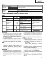
Hitachi DS 12DM User manual
- Category
- Cordless combi drills
- Type
- User manual
Page is loading ...
Page is loading ...
Page is loading ...
Page is loading ...

4
English Deutsch Français Italiano
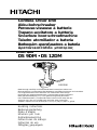
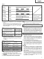
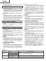
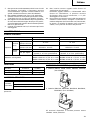
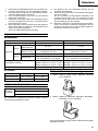
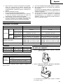
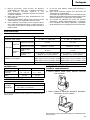
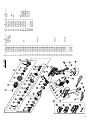
Rechargeable battery
(For DS9DM)
Rechargeable battery
(For DS12DM)
Latch
Pull out
Insert
Handle
Push
Insert
Pilot lamp
Hole for connecting the
rechargeable battery
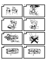
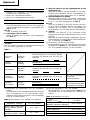
Drill mark
Clutch dial
Triangle mark
Weak
Strong
Line
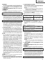
Shift knob
Low speed
High speed
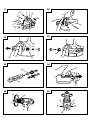
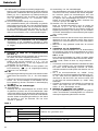
Hook
Loosen
Spring
Larger diameter faces
away
Protruded section
Groove
Sleeve
Tighten
Loosen
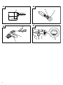
Trigger switch
Selector button
R
and
L
marks
Wear limit
Nail of carbon brush
Protrusion of carbon
brush
Contact portion outside
brush tube
1
2
3
4
5
6
7
8
9
0
A
B
C
D
E
F
G
H
I
J
K
L
M
N
O
P
Q
R
S
T
U
V
W
X
Y
Aufladbare Batterie
(Für DS9DM)
Aufladbare Batterie
(Für DS12DM)
Verriegelung
Herausziehen
Einsetzen
Handgriff
Drücken
Einsetzen
Kontrollampe
Anschlußloch für
Ladebatterir
Bohrer-Zeichen
Kupplungsskala
Dreiecksmarkierung
Schwach
Stark
Linie
Schaltknopf
Kleine Geschwindigkeit
Große Geschwindigkeit
Haken
Lösen
Feder
Der große Durchmesser
weist zur anderen Seite
Hervorstehender
Abschnitt
Nut
Manschette
Anziehen
Lösen
Trigger
Wählhebel
R
und
L
Zeichen
Verschließgrenze
Klaue der Kohlebürste
Krempe der
Kohlebürste
Kontaktteil außerhalb
des Bürstenrohrs
Batteria ricaricabile
(Per DS9DM)
Batteria ricaricabile
(Per DS12DM)
Fermo
Estrarre
Inserire
Impugnatura
Spingere
Inserire
Spia
Foro di collegamento
della batteria ricaricabile
Simbolo di foratura
Ghiera frizione
Simbolo del triangolo
Debol
Forte
Linea
Manopola di comando
Bassa velocità
Alta velocità
Gancio
Allentare
Molla
Diametro più grande
lontano da sé
Sezione sporgente
Scanalatura
Collare
Stringere
Allentare
Interruttore
Selettore
Segno
R
,
L
Limite di usura
Chiodo di spazzola di
carbone
Sporgenza di spazzola
di carbone
Parte di contatto fuori dal
tubo spazzola
Batterie rechargeable
(Pour DS9DM)
Batterie rechargeable
(Pour DS12DM)
Taquet
Tirer vers l’extérieur
Insérer
Poignée
Pousser
Insérer
Lampe témoin
Orifice de
raccordemente de la
batterie rechargeable
Indice de forage
Sélecteur de débrayage
Triangle
Faible
Fort
Ligne
Bouton de décalage
Vitesse ralentie
Vitesse élevée
Crochet
Desserrer
Ressort
Gros diamètre dirigé
vers l’extérieur
Section en saillie
Rainure
Manchon
Serrer
Desserrer
Déclencheur
Sélecteur
Indices
R
et
L
Limite d'usure
Clou de balai en carbone
Saillie de balai en
carbone
Section de contact à
l’extérieur du tube
de balai
Page is loading ...

English
6
GENERAL OPERATIONAL PRECAUTIONS
1. Keep work area clean. Cluttered areas and benches
invite accidents.
2. Avoid dangerous environment. Don’t expose power
tools and charger to rain. Don’t use power tools
and charger in damp or wet locations. And keep
work area well lit. Never use power tools and charger
near flammable or explosive materials. Do not use
tool and charger in presence of flammable liquids
or gases.
3. The appliance is not intended for use by young
children or infirm persons without supervision.
Young children should be supervised to ensure
that they do not play with the appliance. All visitors
should be kept safe distance from work area.
4. Store idle tools and charger. When not in use, tools
and charger should be stored in dry, high or locked-
up place – out of reach of the children and infirm
persons. Store tools and charger in a place where
the temperature is less than 40°C.
5. Don’t force tool. It will do the job better and safer at
the rate for which it was designed.
6. Use right tool. Don’t force small tool or attachment
to do the job of a heavy duty tool.
7. Wear proper apparel. Do not wear loose clothing or
jewelry. They can be caught in moving parts. Rubber
gloves and non-skid footwears are recommended
when working outdoor.
8. Use eye protection with most tools. Also use face
or dust mask if cutting operation is dusty.
9. Don’t abuse cord. Never carry charger by cord or
yank it to disconnect from receptacle. Keep cord
from heat, oil and sharp edges.
10. Secure work. Use clamps or a vise to hold work. It’s
safer than using your hand and it frees both hands
to operate tool.
11. Don’t overreach. Keep proper footing and balance
at all times.
12. Maintain tools with care. Keep tools sharp at all
times, and clean for best and safest performance.
Follow instructions for lubricating and changing
accessories.
13. When the charger is not in use, or when being
maintained and inspected, disconnect its power
cord from the receptacle.
14. Remove chuck wrenches and wrenches. Form habit
of checking to see that wrenches are removed from
tool before turning it on.
15. Avoid accidental starting. Don’t carry tool with finger
on switch.
16. To avoid danger, always use only the specified
charger.
17. Use only genuine HITACHI replacement parts.
18. Do not use power tools for applications other than
those specified in the Handling Instructions.
19. To avoid personal injury, use only the accessories
or attachment recommended in these handling
instructions or in the HITACHI catalog.
20. If the supply cord of this charger is damaged, the
charger must be returned to the HITACHI authorized
service center for the cord to be replaced. Let only
the authorized service center do the repairing. The
Manufacturer will not be responsible for any
damages or injuries caused by repair by the
unauthorized persons or by mishandling of the tool.
21. To ensure the designed operational integrity of
power tools and charger, do not remove installed
covers or screws.
22. Always use the charger at the voltage specified on
the nameplate.
23. Do not touch movable parts or accessories unless
the battery has been removed.
24. Always charge the battery before use.
25. Never use a battery other than that specified. Do
not connect a usual dry cell, a rechargeable battery
other than that specified or a car battery to the
power tool.
26. Do not use any transformer that has a booster.
27. Do not charge the battery from an engine electric
generator or DC power supply.
28. Always charge indoors. Because the charger and
battery heat slightly during charging, charge the
battery in a place not exposed to direct sunlight;
where the humidity is low and the ventilation is
good.
29. When working in a high place, pay attention to the
activities below to make sure there are no people
below.
30. Use the exploded assembly drawing on this
handling instructions only for authorized servicing.
31. If the supply cord is damaged, it must be replaced
by the manufacture or its service agent or a similarly
qualified person in order to avoid a hazard.
PRECAUTIONS FOR CORDLESS DRIVER DRILL
1. Always charge the battery at a temperature of 10 –
40°C. A temperature of less than 10°C will result in
over charging which is dangerous. The battery
cannot be charged at a temperature higher than
40°C.
The most suitable temperature for charging is that
of 20 – 25°C.
2. When one charging is completed, leave the charger
for about 15 minutes before the next charging of
battery.
Do not charge more than two batteries
consecutively.
3. Do not allow foreign matter to enter the hole for
connecting the rechargeable battery.
4. Never disassemble the rechargeable battery and
charger.
5. Never short-circuit the rechargeable battery. Short-
circuiting the battery will cause a great electric
current and overheat. It results in burn or damage
to the battery.
6. Do not dispose of the battery in fire.
If the battery is burnt, it may explode.
7. When drilling in wall, floor or ceiling, check for
buried electric power cord, etc.
8. Bring the battery to the shop from which it was
purchased as soon as the post-charging battery life
becomes too short for practical use. Do not dispose
of the exhausted battery.
9. Using an exhausted battery will damage the charger.
10. Do not insert object into the air ventilation slots of
the charger.
Inserting metal objects or inflammables into the
charger air ventilation slots will result in electrical
shock hazard or damaged charger.
11. When mounting a bit into the keyless chuck, tighten
the sleeve adequately. If the sleeve is not tight, the
bit may slip or fall out, causing injury.

English
7
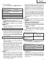
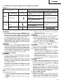
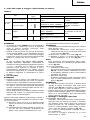
SPECIFICATIONS
POWER TOOL
CHARGER
Model UC14YFA UC18YG
Charging voltage 7.2 – 14.4 V 7.2 – 18 V
Weight 0.6 kg 0.3 kg
STANDARD ACCESSORIES
Standard accessories are subject to change without notice.
OPTIONAL ACCESSORIES (sold separately)
1. Battery (EB914, EB9B, EB9H, EB926H, EB930H)
(For DS9DM)
2. Battery (EB1214L, EB1220BL, EB1222HL, EB1226HL,
EB1230HL) (For DS12DM)
Optional accessories are subject to change without notice.
Model DS9DM DS12DM
No-load speed (Low/High) 0 – 330 / 0 – 1150 min
–1
0–350 / 0 – 1200 min
–1
Wood
Drilling
(Thickness 18 mm)
21 mm 27 mm
Metal Steel: 10 mm, Steel: 13 mm,
(Thickness 1.6 mm)
Aluminum: 10 mm Aluminum: 13 mm
Machine screw 6 mm 6 mm
Driving
Wood screw
6.2 mm (diameter) × 56 mm (length) 6.8 mm (diameter) × 50 mm (length)
(Requires a pilot hole) (Requires a pilot hole)
EB9B : Ni-Cd 9.6 V (2.0 Ah, 8 cells)
EB1220BL : Ni-Cd 12 V (2.0 Ah, 10 cells)
Rechargeable battery
EB926H : Ni-MH9.6 V (2.6 Ah, 8 cells)
EB1226HL : Ni-MH 12 V (2.6 Ah, 10 cells)
EB930H : Ni-MH9.6 V (3.0 Ah, 8 cells)
EB1230HL : Ni-MH 12 V (3.0 Ah, 10 cells)
Weight 1.5 kg 1.7 kg
Capacity
DS9DM
1 Plus driver bit (No. 2) .................. 1
DS12DM
2 Charger (UC14YFA or UC18YG) .... 1
3 Plastic case....................................... 1
APPLICATIONS
䡬 Driving and removing of machine screws, wood
screws, tapping screws, etc.
䡬 Drilling of various metals.
䡬 Drilling of various woods.
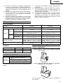
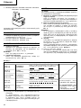
BATTERY REMOVAL/INSTALLATION
1. Battery removal
Hold the handle tightly and push the battery latch
to remove the battery (See Figs. 1 and 2).
CAUTION
Never short-circuit the battery.
2. Battery installation
Insert the battery while observing its polarities (See
Fig. 2).
CHARGING
〈UC14YFA
〉
Before using the driver drill, charge the battery as follows.
1. Connect the charger’s power cord to a receptacle
When the power cord is connected, the charger’s
pilot lamp will blink in red (At 1-second intervals).
2. Insert the battery into the charger
Firmly insert the battery into the charger till it
contacts the bottom of the charger and checking
the polarities as shown in Fig. 3.
CAUTION
If the batteries are inserted in the reverse direction,
not only recharging will become impossible, but it
may also cause problems in the charger such as
a deformed recharging terminal.
3. Charging
When inserting a battery in the charger, charging
will commence and the pilot lamp will light
continuously in red.
When the battery becomes fully recharged, the pilot
lamp will blink in red (At 1-second intervals.) (See
Table 1).
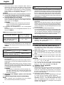
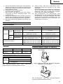
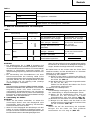
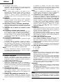
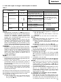
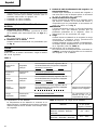
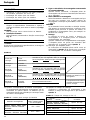
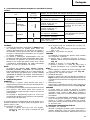
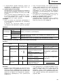
(1) Pilot lamp indication
The indications of the pilot lamp will be as shown
in Table 1, according to the condition of the charger
or the rechargeable battery.

English
8
Lights for 0.5 seconds. Does not light for 0.5
seconds. (off for 0.5 seconds)
Lights continuously
Lights for 0.5 seconds. Does not light for 0.5
seconds. (off for 0.5 seconds)
Lights for 0.1 seconds. Does not light for 0.1
seconds. (off for 0.1 seconds)
Lights continuously
Before
charging
While
charging
Charging
complete
Charging
impossible
Blinks
(RED)
Lights
(RED)
Blinks
(RED)
Flickers
(RED)
Lights
(GREEN)
Malfunction in the bat-
tery or the charger.
The battery temperature
is high, making recharg-
ing impossible.
Table 1
Indications of the pilot lamp
Charging
impossible
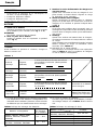
(2) Regarding the temperatures of the rechargeable
battery
The temperatures for rechargeable batteries are as
shown in the table below, and batteries that have
become hot should be cooled for a while before
being recharged.
Table 2 Recharging ranges of batteries
(3) Regarding recharging time
Depending on the combination of the charger and
batteries, the charging time will become as shown
in Table 3.
Table 3 Charging time (At 20°C)
NOTE
The charging time may vary according to
temperature and power source voltage.
4. Disconnect the charger’s power cord from the
receptacle
5. Hold the charger firmly and pull out the battery
Temperatures at
Rechargeable batteries
which the battery
can be recharged
EB912S, EB914S, EB914, EB9B,
EB1212S, EB1214S, EB1214L, –5°C – 60°C
EB1220BL
EB9H, EB926H, EB930H,
0°C – 45°C
EB1222HL, EB1226HL, EB1230HL
NOTE
After operation, pull out batteries from the charger
first, and then keep the batteries properly.
Regarding electric discharge in case of new batteries,
etc.
As the internal chemical substance of new batteries
and batteries that have not been used for an
extended period is not activated, the electric
discharge might be low when using them the first
and second time. This is a temporary phenomenon,
and normal time required for recharging will be
restored by recharging the batteries 2 – 3 times.
How to make the batteries perform longer.
(1) Recharge the batteries before they become
completely exhausted.
When you feel that the power of the tool becomes
weaker, stop using the tool and recharge its battery.
If you continue to use the tool and exhaust the
electric current, the battery may be damaged and
its life will become shorter.
(2) Avoid recharging at high temperatures.
A rechargeable battery will be hot immediately after
use. If such a battery is recharged immediately after
use, its internal chemical substance will deteriorate,
and the battery life will be shortened. Leave the
battery and recharge it after it has cooled for a
while.
CAUTION
䡬 If the battery is charged while it is heated because
it has been left for a long time in a location subject
to direct sunlight or because the batetery has just
been used, the pilot lamp of the charger lights up
green. In such a case, first let the battery cool, then
start charging.
䡬 When the pilot lamp flickers in red (at 0.2-second
intervals), check for and take out any foreign objects
in the charger’s battery installation hole. If there are
no foreign objects, it is probable that the battery
or charger is malfunctioning. Take it to your
authorized Service Center.
Charger
UC14YFA
Battery
EB912S, EB914S,
EB914, EB1212S, Approx. 30 min.
EB1214S, EB1214L
EB9B, EB1220BL Approx. 50 min.
EB9H, EB1222HL Approx. 55 min.
EB926H, EB1226HL Approx. 60 min.
EB930H, EB1230HL Approx. 70 min.

English
9
䡬 Since the built-in micro computer takes about 3
seconds to confirm that the battery being charged
with UC14YFA is taken out, wait for a minimum of
3 seconds before reinserting it to continue charging.
If the battery is reinserted within 3 seconds, the
battery may not be properly charged.
〈
UC18YG
〉
Before using the driver drill, charge the battery as follows.
1. Connect the charger power cord to the receptacle
Connecting the power cord will turn on the charger.
2. Insert the battery into the charger
Insert the battery firmly while observing its direction,
until it contacts the bottom of the charger (the pilot
lamp lights up) (See Fig. 4).
CAUTION
If the pilot lamp does not light up, pull out the
power cord from the receptacle and check the
battery mounting condition.
(1) Regarding the temperatures of the rechargeable
battery
The temperatures for rechargeable batteries are as
shown in Table 4.
Table 4 Recharging ranges of batteries
(2) Regarding recharging time
Depending on the combination of the charger and
batteries, the charging time will become as shown in
Table 5.
Table 5 Charging time (At 20°C)
The pilot lamp goes off to indicate that the battery is
fully charged.
The battery charging time becomes longer when a
temperature is low or the voltage of the power source
is too low.
When the pilot lamp does not go off even if more
than 120 minutes have elapsed after starting of the
charging, stop the charging and contact your HITACHI
AUTHORIZED SERVICE CENTER.
CAUTION
If the battery is heated due to direct sunlight, etc.,
just after operation, the charger pilot lamp may
not light up. At that time, cool the battery first,
then start charging.
3. Disconnect the charger’s power cord from the
receptacle
4. Hold the charger firmly and pull out the battery
NOTE
After charging, pull out batteries from the charger
first, and then keep the batteries properly.
Regarding electric discharge in case of new batteries,
etc.
As the internal chemical substance of new batteries
and batteries that have not been used for an extended
period is not activated, the electric discharge might
be low when using them the first and second time.
This is a temporary phenomenon, and normal time
required for recharging will be restored by recharging
the batteries 2 – 3 times.
How to make the batteries perform longer.
(1) Recharge the batteries before they become completely
exhausted.
When you feel that the power of the tool becomes
weaker, stop using the tool and recharge its battery.
If you continue to use the tool and exhaust the electric
current, the battery may be damaged and its life will
become shorter.
(2) Avoid recharging at high temperatures.
A rechargeable battery will be hot immediately after
use. If such a battery is recharged immediately after
use, its internal chemical substance will deteriorate,
and the battery life will be shortened. Leave the battery
and recharge it after it has cooled for a while.
PRIOR TO OPERATION
1. Setting up and checking the work environment
Check if the work environment is suitable by
following the precautions.
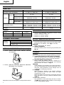
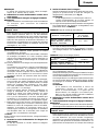
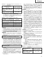
HOW TO USE
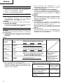
1. Confirm the clutch dial position (See Fig. 5)
The tightening torque of this unit can be adjusted
according to the clutch dial position, at which the
clutch dial is set.
(1) When using this unit as a screwdriver, line up the
one of the numbers “1, 3, 5 ... 22” on the clutch
dial, or the dots, with the triangle mark on the outer
body.
(2) When using this unit as a drill, align the clutch dial
drill mark “
” with the triangle mark on the outer
body.
CAUTION
䡬 The clutch dial cannot be set between the numerals
“1, 3, 5 ... 22” or the dots.
䡬 Do not use with the clutch dial numeral between
“22” and the line at the middle of the drill mark.
Doing so may cause damage (See Fig. 6).
2. Tightening torque adjustment
(1) Tightening torque
Tightening torque should correspond in its intensity
to the screw diameter. When too strong torque is
used, the screw head may be broken or be injured.
Be sure to adjust the clutch dial position according
to the screw diameter.
(2) Tightening torque indication
The tightening torque differs depending on the type
of screw and the material being tightened.
The unit indicates the tightening torque with the
numbers “1, 3, 5 ... 22” on the clutch dial, and a
dots. The tightening toque at position “1” is the
weakest and the torque is strongest at the highest
number (See Fig. 5).
Temperatures at
Rechargeable batteries which the battery
can be recharged
EB912S, EB914S, EB914,
EB9B, EB1212S, EB1214S, 0°C – 45°C
EB1214L, EB1220BL
Charger
UC18YG
Battery
EB912S, EB914S, EB914,
Approx. 30 min.
EB1212S, EB1214S, EB1214L
EB9B, EB1220BL
Approx. 50 min.

English
10
CAUTION
䡬 The selection examples shown in Table 7 should
be considered as general standard. As different
types of tightening screws and different materials
to be tightened are used in actual works proper
adjustments are naturally necessary.
䡬 When using the driver drill with a machine screw
at HIGH (high speed), a screw may damage or a
bit may loose due to the tightning torque is too
strong. Use the driver drill at LOW (low speed)
when using a machine screw.
NOTE
The use of the battery EB9H, EB926H, EB930H,
EB1222HL, EB1226HL and EB1230HL in a cold
condition (below 0 degree Centigrade) can
sometimes result in the weakened tightening torque
and reduced amount of work. This, however, is
a temporary phenomenon, and returns to normal
when the battery warms up.
6. Using the hook
CAUTION
䡬 When using the hook, pay sufficient attention so that
the main equipment does not fall. If the tool falls,
there is a risk of accident.
(3) Adjusting the tightening torque
Rotate the clutch dial and line up the numbers “1,
3, 5 ... 22” on the clutch dial, or the dots, with the
triangle mark on the outer body. Adjust the clutch
dial in the weak or the strong torque direction
according to the torque you need.
CAUTION
䡬 The motor rotation may be locked to cease while
the unit is used as drill. While operating the driver
drill, take care not to lock the motor.
䡬 Too long hammering may cause the screw broken
due to excessive tightening.
3. Change rotation speed
Operate the shift knob to change the rotational
speed. Move the shift knob in the direction of the
arrow (See Figs. 7 and 8).
When the shift knob is set to “LOW”, the drill
rotates at a low speed. When set to “HIGH”, the
drill rotates at a high speed.
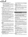
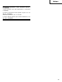
Use Clutch Position
Rotating speed selection (Position of the shift knob)
LOW (Low speed) HIGH (High speed)
Driving
Machine screw 1 – 22
For 4 mm or smaller diameter
screws.
Wood screw 1 –
For 6.2 mm or smaller nominal
diameter screws. (DS9DM)
For 6.8 mm or smaller nominal
diameter screws. (DS12DM)
Drilling
Wood
For 21 mm or smaller
diameters. (DS9DM)
For 27 mm or smaller
diameters.
(DS12DM)
Metal
For drilling with a metal
working drill bit.
For 6 mm or smaller
diameter screws.
For 3.8 mm or smaller
nominal diameter screws.
For 18 mm or smaller
diameters.
Work Suggestions
Wood
Drilling Steel Use for drilling purpose.
Aluminum
Machine screw Use the bit or socket matching the screw diameter.
Driving
Wood screw Use after drilling a pilot hole.
Table 6
CAUTION
䡬 When changing the rotational speed with the shift
knob, confirm that the switch is off.
Changing the speed while the motor is rotating will
damage the gears.
䡬 When setting the shift knob to “HIGH” (high speed)
and the position of the clutch dial is “17” or “22”,
it may happen that the clutch does not engaged
and that the motor is locked. In such a case, please
set the shift knob to “LOW” (low speed).
䡬 If the motor is locked, immediately turn the power
off. If the motor is locked for a while, the motor
or battery may be burnt.
4. The scope and suggestions for uses
The usable scope for various types of work based
on the mechanical structure of this unit is shown
in Table 6.
5. How to select tightening torque and rotational speed
Table 7

English
11
䡬 Do not attach the tip tool except phillips bit to the tool
main unit when carrying the tool main unit with the
hook suspended from a waist belt.
Injury may result if you carry the equipment
suspended from the waist belt with sharp tipped
components such as drill bit attached.
The hook can be installed on the right or left side and the
angle can be adjusted in 5 steps between 0° and 80°.
(1) Operating the hook
(a) Pull out the hook toward you in the direction
of arrow (A) and turn in the direction of arrow
(B) (Fig. 9).
(b) The angle can be adjusted in 5 steps (0°, 20°,
40°, 60°, 80°).
Adjust the angle of the hook to the desired
position for use.
(2) Switching the hook position
CAUTION
Incomplete installation of the hook may result in
bodily injury when used.
(a) Securely hold the main unit and remove the
screw using a slotted head screwdriver or a coin
(Fig. 10).
(b) Remove the hook and spring (Fig. 11).
(c) Install the hook and spring on the other side and
securely fasten with screw (Fig. 12).
NOTE
Pay attention to the spring orientation. Install the
spring with larger diameter away from you (Fig. 12).
(3) Using the bit holder
䡬 Installing the bit
Slide the bit from the side in the direction of Fig. 13,
and then insert firmly until the groove on the bit locks
in the protruded section of the hook.
䡬 Removing the bit
Securely hold the main unit and pull out the bit by
holding the tip with your thumb (Fig. 14).
CAUTION
䡬 The bit may come loose from the hook and cause
bodily injury when reversing the direction of the
bit as shown in Fig. 13 or when using the driver
with the bit stored incomplete.
䡬 Only Hitachi OPTIONAL ACCESSORIES plus driver
bits (Bit No. 2; Code No. 992671, Bit No. 3; Code
No. 992672) may be used. Do not use other bits
since they may come loose.
7. Mounting and dismounting of the bit
(1) Mounting the bit
Loosen the sleeve by turning it toward the left (in
the counterclockwise direction as viewed from the
front) to open the clip on the keyless chuck. After
inserting a driver bit, etc., into the keyless drill
chuck, and tighten the sleeve by turning it toward
the right (in the clockwise direction as viewed from
the front) (See Fig. 15).
If the sleeve becomes loose during operation, tighten
it further.
The tightening force becomes stronger when the
sleeve is tightened additionally.
(2) Dismounting the bit
Loosen the sleeve by turning it toward the left (in
the counterclockwise direction as viewed from the
front), and then take out the bit etc. (See Fig. 15).
NOTE
If the sleeve is tightened in a state where the clip
of the keyless chuck is opened to a maximum limit,
a click noise may occur. This is the noise that occurs
when the loosening of the keyless chuck is prevented
and is not a malfunction.
CAUTION
When it is no longer possible to loosen the sleeve,
use a vise or similar instrument to secure the bit.
Set the clutch mode between 1 and 11 and then
turn the sleeve to the loose side (left side) while
operating the clutch. It should be easy now to
loosen the sleeve.
8. Automatic spindle-lock mechanism
This unit has automatic spindle-lock mechanism for
quick bit changes.
9. Confirm that the battery is mounted correctly
10. Check the rotational direction
The bit rotates clockwise (viewed from the rear
side) by pushing the R-side of the selector button.
The L-side of the selector button is pushed to turn
the bit counterclockwise (See Fig. 16) (The
L
and
R
marks are provided on the body).
11. Switch operation
䡬 When the trigger switch is depressed, the tool
rotates. When the trigger is released, the tool stops.
䡬 The rotational speed of the drill can be controlled
by varying the amount that the trigger switch is
pulled. Speed is low when the trigger switch is
pulled slightly and increases as the trigger switch
is pulled more.
NOTE
A buzzing noise is produced when the motor is
about to rotate; This is only a noise, not a machine
failure.
MAINTENANCE AND INSPECTION
1. Inspecting the tool
Since use of as dull tool will degrade efficiency and
cause possible motor malfunction, sharpen or
replace the tool as soon as abrasion is noted.
2. Inspecting the mounting screws
Regularly inspect all mounting screws and ensure
that they are properly tightened. Should any of the
screws be loose, retighten them immediately. Failure
to do so could result in serious hazard.
3. Maintenance of the motor
The motor unit winding is the very “heart” of the
power tool.
Exercise due care to ensure the winding does not
become damaged and/or wet with oil or water.
4. Inspecting the carbon brushes (Fig. 17)
The motor employs carbon brushes which are
consumable parts. Since and excessively worn
carbon brush can result in motor trouble, replace
the carbon brush with new ones when it becomes
worn to or near the “wear limit”. In addition, always
keep carbon brushes clean and ensure that they
slide freely whthin the brush holders.
NOTE
When replacing the carbon brush with a new one,
be sure to use the Hitachi Carbon Brush Code No.
999054.

English
12
5. Replacing carbon brushes
Take out the carbon brush by first removing the
brush cap and then hooking the protrusion of the
carbon brush with a flat head screw driver, etc., as
shown in Fig. 19.
When installing the carbon brush, choose the
direction so that the nail of the carbon brush agrees
with the contact portion outside the brush tube.
Then push it in with a finger as illustrated in
Fig. 20. Lastly, install the brush cap.
CAUTION
Be absolutely sure to insert the nail of the carbon
brush into the contact portion outside the brush
tube (You can insert whichever one of the two nails
provided).
Caution must be exercised since any error in this
operation can result in the deformed nail of the
carbon brush and may cause motor trouble at an
early stage.
6. Cleaning on the outside
When the driver drill is stained, wipe with a soft
dry cloth or a cloth moistened with soapy water.
Do not use chloric solvents, gasoline or paint thinner,
for they melt plastics.
7. Storage
Store the driver drill in a place in which the tempera
ture is less than 40°C and out of reach of children.
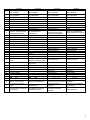
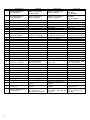
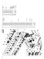
8. Service parts list
A : Item No.
B : Code No.
C : No. Used
D : Remarks
CAUTION
Repair, modification and inspection of Hitachi Power
Tools must be carried out by a Hitachi Authorized
Service Center.
This Parts List will be helpful if presented with the
tool to the Hitachi Authorized Service Center when
requesting repair or other maintenance.
In the operation and maintenance of power tools,
the safety regulations and standards prescribed in
each country must be observed.
MODIFICATIONS
Hitachi Power Tools are constantly being improved
and modified to incorporate the latest technological
advancements.
Accordingly, some parts (i.e. code numbers and/or
design) may be changed without prior notice.
NOTE:
Due to HITACHI’s continuing program of research and
development, the specifications herein are subject to
change without prior notice.
Information concerning airborne noise and vibration
The measured values were determined according to
EN50144.
The typical A-weighted sound pressure level:
70 dB (A). (DS12DM)
Wear ear protection.
The typical weighted root mean square acceleration
value: 2.0m/s
2
. (DS12DM)
Page is loading ...
Page is loading ...
Page is loading ...
Page is loading ...
Page is loading ...
Page is loading ...
Page is loading ...
Page is loading ...
Page is loading ...
Page is loading ...
Page is loading ...
Page is loading ...
Page is loading ...
Page is loading ...
Page is loading ...
Page is loading ...
Page is loading ...
Page is loading ...
Page is loading ...
Page is loading ...
Page is loading ...
Page is loading ...
Page is loading ...
Page is loading ...
Page is loading ...
Page is loading ...
Page is loading ...
Page is loading ...
Page is loading ...
Page is loading ...
Page is loading ...
Page is loading ...
Page is loading ...
Page is loading ...
Page is loading ...
Page is loading ...
Page is loading ...
Page is loading ...
Page is loading ...
Page is loading ...
Page is loading ...
Page is loading ...
Page is loading ...
Page is loading ...
Page is loading ...
Page is loading ...
Page is loading ...
Page is loading ...
Page is loading ...
Page is loading ...
Page is loading ...
Page is loading ...
Page is loading ...
Page is loading ...
Page is loading ...
Page is loading ...

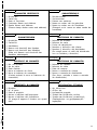
69
DS 9DM
ABCD
40 320-777 3 M3×4
41 320-775 1
42 316-166 1
43 320-287 1 “44”
44 320-288 1 M5
45 306-952 1
46 320-776 1
47 319-926 1
48 319-927 1 M5
49-1 318-368 1 EB930H
49-2 310-377 1 EB9B
49-3 323-225 1 EB926H
501-1 ––––––– 1 UC14YFA
501-2 ––––––– 1 UC18YG
502 322-609 1
503 983-006 1 NO. 2×65L
ABCD
1 311-959 1 M6×23
2 320-683 1 10VLRE-N
3 322-460 1
4 322-461 1
5 320-758 1
6 320-757 1
7 320-756 1
8320-755 1
9320-773 1
10 319-744 6
11 306-936 6 D5
12 320-759 1
13 320-761 1
14 312-708 6
15 320-760 1
16 320-782 3
17 320-762 1
18 320-763 1
19 312-712 4 D3×12
20 320-770 1
21 320-765 1
22 320-764 1
23 320-781 4
24 320-766 1
25 320-780 4
26 320-767 1
27 320-768 1
28 320-769 1
29 360-633 1 DC 9.6V
30 322-520 1
31 322-521 1
32 320-774 1
33 999-054 2 5×6×11.5
34 319-918 2
35 991-672 8 D3×12
36 ––––––– 1
37 ––––––– 1
38 322-608 1
39 320-772 1

70
DS 12DM
ABCD
40 320-777 3 M3×4
41 320-775 1
42 316-166 1
43 320-287 1 “44”
44 320-288 1 M5
45 306-952 1
46 320-776 1
47 319-926 1
48 319-927 1 M5
49-1 320-387 1 EB1220BL
49-2 320-388 1 EB1230HL
49-3 323-226 1 EB1226HL
501-1 ––––––– 1 UC14YFA
501-2 ––––––– 1 UC18YG
502 321-916 1
503 983-006 1
ABCD
1 311-959 1 M6×23
2 320-684 1 13VLRG-N
3 322-460 1 “4-8, 10-28”
4 322-461 1
5 320-758 1
6 320-757 1
7 320-756 1
8320-755 1
9320-773 1
10 319-744 6
11 306-936 6 D5
12 320-759 1
13 320-761 1
14 312-708 6
15 320-760 1
16 320-782 3
17 320-762 1
18 320-763 1
19 312-712 4 D3×12
20 320-770 1
21 320-765 1
22 320-764 1
23 320-781 4
24 320-766 1
25 320-780 4
26 320-767 1
27 320-768 1
28 320-769 1
29 360-627 1 DC12V
30 322-520 1
31 322-521 1
32 320-774 1
33 999-054 2
34 319-918 2
35 313-687 8 D3×16
36 ––––––– 1
37 ––––––– 1
38 322-462 1
39 320-772 1
Page is loading ...

72
English Nederlands
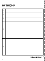
GUARANTEE CERTIFICATE
1 Model No.
2 Serial No.
3 Date of Purchase
4 Customer Name and Address
5 Dealer Name and Address
(Please stamp dealer name and address)
Italiano Ελληνικά
Français Português
Deutsch
Español
GARANTIEBEWIJS
1 Modelnummer
2 Serienummer
3 Datum van aankoop
4 Naam en adres van de gebruiker
5 Naam en adres van de handelaar
(Stempel a.u.b. naam en adres vande de
handelaar)
GARANTIESCHEIN
1 Modell-Nr.
2 Serien-Nr.
3 Kaufdaturn
4 Name und Anschrift des Kunden
5 Name und Anschrift des Händlers
(Bitte mit Namen und Anschrift des
Handlers abstempeln)
CERTIFICADO DE GARANTIA
1 Número de modelo
2 Número de serie
3 Fecha de adquisición
4 Nombre y dirección del cliente
5 Nombre y dirección del distribudor
(Se ruega poner el sellú del distribudor
con su nombre y dirección)
CERTIFICAT DE GARANTIE
1 No. de modèle
2 No de série
3 Date d'achat
4 Nom et adresse du client
5 Nom et adresse du revendeur
(Cachet portant le nom et l'adresse du
revendeur)
CERTIFICADO DE GARANTIA
1 Número do modelo
2 Número do série
3 Data de compra
4 Nome e morada do cliente
5 Nome e morada do distribuidor
(Por favor, carímbe o nome e morada
do distribuidor)
CERTIFICATO DI GARANZIA
1 Modello
2 N° di serie
3 Data di acquisto
4 Nome e indirizzo dell'acquirente
5 Nome e indirizzo del rivenditore
(Si prega di apporre il timbro con questi
dati)
¶π™∆√¶√π∏∆π∫√ ∂°°À∏™∏™
1 Αρ. Μντέλυ
2 Αύων Αρ.
3 Ηµερµηνία αγράς
4 ΄νµα και διεύθυνση πελάτη
5 ΄νµα και διεύθυνση µεταπωλητή
(Παρακαλύµε να ρησιµπιηθεί
σραγίδα)
✄
Page is loading ...
Page is loading ...
Page is loading ...
Page is loading ...

English
EC DECLARATION OF CONFORMITY
We declare under our sole responsibility that this
product is in conformity with standards or standard-
ized documents EN50144 and EN55014-2 in accordance
with Council Directives 89/336/EEC and 98/37/EC.
This declaration is applicable to the product affixed CE
marking.
Deutsch
ERKLÄRUNG ZUR KONFORMITÄT MIT CE-REGELN
Wir erklären mit alleiniger Verantwortung, daß dieses
Produkt den Standards oder standardisierten
Dokumenten EN50144 und EN55014-2 in
Übereinstimmung mit den Direktiven des Europarats
89/336/EWG und 98/37/CE entspricht.
Diese Erklärung gilt für Produkte, die die CE-Markierung
tragen.
Français
DECLARATION DE CONFORMITE CE
Nous déclarons sous notre seule et entière respon-
sabilité que ce produit est conforme aux normes ou
documents normalisés EN50144 et EN55014-2 en accord
avec les Directives 89/336/CEE et 98/37/CE du Conseil.
Cette déclaration s’applique aux produits désignés CE.
Italiano
DICHIARAZIONE DI CONFORMITÀ CE
Si dichiara sotto nostra responsabilità che questo
prodotto è conforme agli standard o ai documenti
standardizzati EN50144 e EN55014-2 conforme alle
direttive 89/336/CEE e 98/37/CE del concilio.
Questa dichiarazione è applicabile ai prodotti cui sono
applicati i marchi CE.
Representative office in Europe
Hitachi Power Tools Europe GmbH
Siemensring 34, 47877 Willich 1, F. R. Germany
Head office in Japan
Hitachi Koki Co., Ltd.
Shinagawa Intercity Tower A, 15-1, Konan 2-chome,
Minato-ku, Tokyo, Japan
Nederlands
EC VERKLARING VAN CONFORMITEIT
Wij verklaren onder eigen verantwoordelijkheid dat dit
produkt conform de richtlijnen of gestandardiseerde
documenten EN50144 en EN55014-2 voldoet aan de
eisen van EEG Bepalingen 89/336/EEG en 98/37/EC.
Deze verklaring is van toepassing op produkten
voorzien van de CE-markeringen.
Español
DECLARACIÓN DE CONFORMIDAD DE LA CE
Declaramos bajo nuestra única responsabilidad que
este producto está de acuerdo con las normas o con
los documentos de normalización EN50144 y EN55014-
2 según indican las Directrices del Consejo 89/336/CEE
y 98/37/CE.
Esta declaración se aplica a los productos con marcas
de la CE.
Português
DECLARAÇÃO DE CONFORMIDADE CE
Declaramos, sob nossa única e inteira responsabilidade,
que este produto está de acordo com as normas ou
documentos normativos EN50144 e EN55014-2 em
conformidade com as Diretrizes 89/336/CEE e 98/37/CE
do Conselho.
Esta declaração se aplica aos produtos designados CE.
Ελληνικά
EK ∆ΗΛΩΣΗ ΕΝΑΡΜΝΙΣΜΥ
∆ηλώνυµε µε απ'λυτη υπευθυν'τητα 'τι αυτ' τ
πρι'ν είναι εναρµνισµέν µε τα πρ'τυπα ή τα
έγρα)α πρτύπων EN50144 και EN55014-2 σε
συµ)ωνία µε τις δηγίες τυ Συµυλίυ 89/336/EOK
και 98/37/EK.
Αυτή η δήλωση ισύει στ πρι'ν µε τ σηµάδι EC.
503
Code No. C99112074
Printed in China
28. 2. 2004
K. Kato
Board Director
Hitachi Koki Co., Ltd.
-
 1
1
-
 2
2
-
 3
3
-
 4
4
-
 5
5
-
 6
6
-
 7
7
-
 8
8
-
 9
9
-
 10
10
-
 11
11
-
 12
12
-
 13
13
-
 14
14
-
 15
15
-
 16
16
-
 17
17
-
 18
18
-
 19
19
-
 20
20
-
 21
21
-
 22
22
-
 23
23
-
 24
24
-
 25
25
-
 26
26
-
 27
27
-
 28
28
-
 29
29
-
 30
30
-
 31
31
-
 32
32
-
 33
33
-
 34
34
-
 35
35
-
 36
36
-
 37
37
-
 38
38
-
 39
39
-
 40
40
-
 41
41
-
 42
42
-
 43
43
-
 44
44
-
 45
45
-
 46
46
-
 47
47
-
 48
48
-
 49
49
-
 50
50
-
 51
51
-
 52
52
-
 53
53
-
 54
54
-
 55
55
-
 56
56
-
 57
57
-
 58
58
-
 59
59
-
 60
60
-
 61
61
-
 62
62
-
 63
63
-
 64
64
-
 65
65
-
 66
66
-
 67
67
-
 68
68
-
 69
69
-
 70
70
-
 71
71
-
 72
72
-
 73
73
-
 74
74
-
 75
75
-
 76
76
-
 77
77
-
 78
78


Hitachi DS 12DM User manual
- Category
- Cordless combi drills
- Type
- User manual
Ask a question and I''ll find the answer in the document
Finding information in a document is now easier with AI
in other languages
- italiano: Hitachi DS 12DM Manuale utente
- français: Hitachi DS 12DM Manuel utilisateur
- español: Hitachi DS 12DM Manual de usuario
- Deutsch: Hitachi DS 12DM Benutzerhandbuch
- Nederlands: Hitachi DS 12DM Handleiding
- português: Hitachi DS 12DM Manual do usuário
Related papers
-
Hitachi DS 12DM User manual
-
-
-
-
-
Hitachi WH 12DAF2 User manual
-
-
-
-
Other documents
-
 Oleo-Mac ba 2,6 ah Owner's manual
-
Black and Decker GC1440 User manual
-
Panasonic EY7960 User manual
-
Panasonic RQSX55 Operating instructions
-
Milwaukee 2664-059 User manual
-
Skil 2255 User manual
-
Makita bdf 460 Owner's manual
-
Makita HR2450X User manual
-
-
Black & Decker PD400L User manual
