10-8-2010 4 ebode IR LINK C
2. Introduction
Congratulations on purchasing the ebode IR Link C. Our ebode proprietary eIR
2
x
TM
(pronounce Irex) Technology guarantees a high level of immunity for InfraRed noise from
direct sunlight, CFL lighting and Flat Panel TV’s (including Plasma, LCD and LED). It
provides accurate reproduction of the latest generation InfraRed codes that are used in
remote controls of, for instance, set-top boxes and media players (incl. RC5/6, RCMM,
XMP).
The IR Link C is a mains powered InfraRed Extender System that allows full remote control
operation of audio/video components (such as your Blu-ray player, A/V Receiver, DVR,
Satellite Box, Cable Tuner, etc.) which are located in another room and makes use of
existing coax cable (CATV).
An InfraRed Extender in general consists of an IR (InfraRed) capture device, the Receiver,
a distribution circuit/connecting block, the Hub, and finally the IR LED output, the Emitter,
which flashes the IR signal to the A/V component.
3. Set content
The ebode IR Link C consists of the following supplied parts:
1. One InfraRed Receiver, Model IRLP. It is placed at the remote room location to receive
IR signals from the handheld remote controller.
2. One INJ Injector. This unit, located in the remote room, injects the remote control signal
into the room to- room coaxial cable (along with the TV signal) and passes it to the CPL
Coupler in the main room. It also provides quick connection of the IRLP IR Receiver and
12VDC power supply cables.
3. One CPL Coupler. Located in the main room, this Coupler extracts the remote control
signal from the coaxial cable and passes it to the emitters that control your source
equipment. In addition, the CPL contains a 2-way RF splitter so that the TV signal can be
fed to a local TV.
4. One Triple Blinking IR Emitter, model 3IREDB. The Emitters on this device allow control of
three InfraRed remote controlled audio/video components. The IR Emitters have a self
adhesive film on one surface of each Emitter. This allows them to be “stuck” to the IR sensor
“window” on your source equipment. There is a set of replacement adhesive pads
included.
5. A 12VDC Power Supply. This plugs into a 230V~50Hz
outlet to provide power to the IRLP Receiver.
6. 3 extra replacement adhesives for the IR Emitters
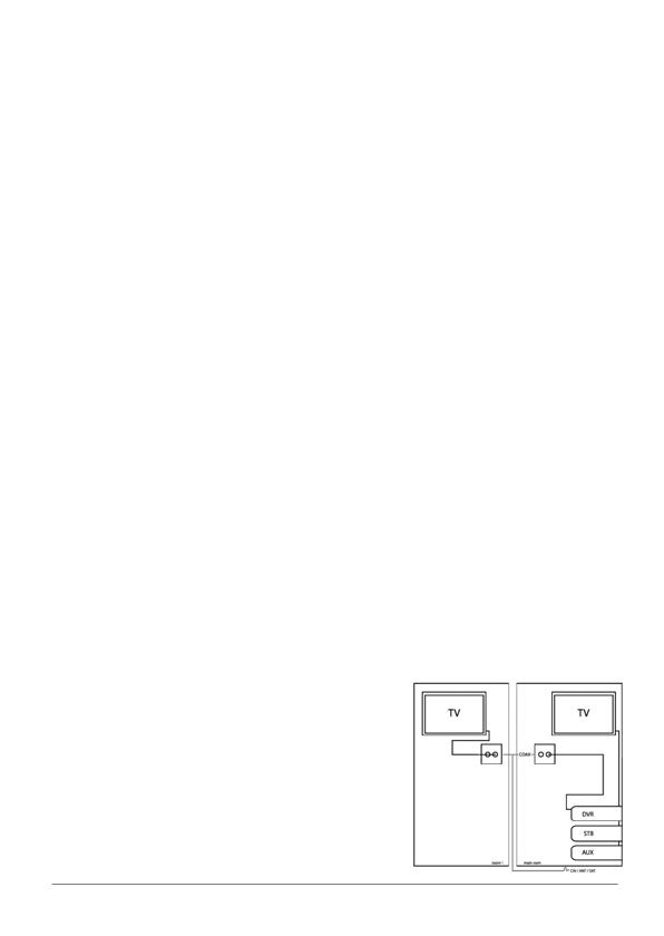
4. How does the ebode IR Link C work?
The ebode IR Link C system uses the coaxial cable that
carries the TV RF signal from the source equipment in
the main room to the remote room, to send the IR
control signals back to the source equipment. The
coaxial cable may be up to 300m in length. If you
already have a coaxial cable connecting your video


