VTC Pro Audio V42 Owner's manual
- Category
- Audio amplifiers
- Type
- Owner's manual
This manual is also suitable for

OWNER’S MANUAL
MANUEL DE L’UTILISATEUR
V44
POWER AMPLIFIER
V42
POWER AMPLIFIER
MODEL TYPE: YS4020
MODEL TYPE: YS4040

The exclamation point within an equilatereal triangle is
intended to alert the user to the presence of important
operating and maintenance (servicing) instructions in
the literature accompanying the appliance.
Le point d’exclamation à l’intérieur d’un triangle équilatéral
est prévu pour alerter l’utilisateur de la présence
d’instructions importantes dans la littérature accompag-
nant l’appareil en ce qui concerne l’opération et la
maintenance de cet appareil.
This lightning flash with arrowhead symbol, within
an equilateral triangle, is intended to alert the user to
the presence of uninsulated “dangerous voltage”
within the product’s enclosure that may be of sufficient
magnitude to constitute a risk of electric shock to persons.
Ce symbole d’éclair avec tête de flèche dans un triangle
équilatéral est prévu pour alerter l’utilisateur de la présence d’un
« voltage dangereux » non-isolé à proximité de l’enceinte du
produit qui pourrait être d’ampleur suffisante pour présenter
un risque de choque électrique.
IMPORTANT SAFETY INSTRUCTIONS
safety-4v7 • May 7/2008
CAUTION: TO REDUCE THE RISK OF ELECTRIC
SHOCK, DO NOT REMOVE COVER (OR BACK).
NO USER SERVICEABLE PA RTS INSIDE.
REFER SERVICING TO QUALIFIED
SERVICE PERSONNEL.
FOLLOW ALL INSTRUCTIONS SUIVEZ TOUTES LES INSTRUCTIONS
Instructions pertaining to a risk of fire,
electric shock, or injury to a person
Read Instructions: The Owner’s Manual should be read and understood before operation
of your unit. Please, save these instructions for future reference and heed all warnings.
Clean only with dry cloth.
Packaging: Keep the box and packaging materials, in case the unit needs to be
returned for service.
Warning: To reduce the risk or fire or electric shock, do not expose this apparatus to rain or
moisture. Do not use this apparatus near water!
Warning: When using electric products, basic precautions should always be followed,
including the following:
Power Sources
Your unit should be connected to a power source only of the voltage specified in the
owners manual or as marked on the unit. This unit has a polarized plug. Do not use
with an extension cord or receptacle unless the plug can be fully inserted. Precau-
tions should be taken so that the grounding scheme on the unit is not defeated. An
apparatus with CLASS I construction shall be connected to a Mains socket outlet with
a protective earthing ground. Where the MAINS plug or an appliance coupler is used
as the disconnect device, the disconnect device shall remain readily operable.
Hazards
Do not place this product on an unstable cart, stand, tripod, bracket or table. The
product may fall, causing serious personal injury and serious damage to the product.
Use only with cart, stand, tripod, bracket, or table recommended by the manufacturer
or sold with the product. Follow the manufacturer’s instructions when installing the
product and use mounting accessories recommended by the manufacturer. Only use
attachments/accessories specified by the manufacturer
Note: Prolonged use of headphones at a high volume may cause
health damage on your ears.
The apparatus should not be exposed to dripping or splashing water; no objects
filled with liquids should be placed on the apparatus.
Te rminals marked with the “lightning bolt” are hazardous live; the external wiring
connected to these terminals require installation by an instructed person or the use of
ready made leads or cords.
Ensure that proper ventilation is provided around the appliance. Do not install near
any heat sources such as radiators, heat registers, stoves, or other apparatus
(including amplifiers) that produce heat.
No naked flame sources, such as lighted candles, should be placed on the apparatus.
Power Cord
Do not defeat the safety purpose of the polarized or grounding-type plug. A polarized plug
has two blades with one wider than the other. A grounding type plug has two blades and a
third grounding prong. The wide blade or the third prong are provided for your safety. If the
provided plug does not fit into your outlet, consult an electrician for replacement of the
obsolete outlet. The AC supply cord should be routed so that it is unlikely that it will be
damaged. Protect the power cord from being walked on or pinched particularly at plugs. If
the AC supply cord is damaged DO NOT OPERATE THE UNIT. To completely disconnect
this apparatus from the AC Mains, disconnect the power supply cord plug from the AC
receptacle. The mains plug of the power supply cord shall remain readily operable.
Unplug this apparatus during lightning storms or when unused for long periods of time.
Service
The unit should be serviced only by qualified service personnel. Servicing is required
when the apparatus has been damaged in any way, such as power-supply cord or plug is
damaged, liquid has been spilled or objects have fallen into the apparatus, the apparatus
has been exposed to rain or moisture, does not operate normally, or has been dropped.
AVIS: AFIN DE REDUIRE LES RISQUE DE CHOC
ELECTRIQUE, N’ENLEVEZ PAS LE COUVERT (OU LE
PANNEAU ARRIERE) NE CONTIENT AUCUNE PIECE
REPARABLE PAR L’UTILISATEUR.
CONSULTEZ UN TECHNICIEN QUALIFIE
POUR L’ENTRETIENT
Instructions relatives au risque de feu,
choc électrique, ou blessures aux personnes
Veuillez Lire le Manuel: Il contient des informations qui devraient êtres comprises avant
l’opération de votre appareil. Conservez. Gardez S.V. P. ces instructions pour consultations
ultérieures et observez tous les avertissements.
Nettoyez seulement avec le tissu sec.
Emballage: Conservez la boite au cas ou l’appareil devait être retourner pour réparation.
Avertissement: Pour réduire le risque de feu ou la décharge électrique, n'exposez pas
cet appareil à la pluie ou à l'humidité. N’utilisez pas cet appareil près de l’eau!
Attention: Lors de l’utilisation de produits électrique, assurez-vous d’adhérer à des
précautions de bases incluant celle qui suivent:
Alimentation
L’ appareil ne doit être branché qu’à une source d’alimentation correspondant au
voltage spécifié dans le manuel ou tel qu’indiqué sur l’appareil. Cet appareil est équipé
d’une prise d’alimentation polarisée. Ne pas utiliser cet appareil avec un cordon de
raccordement à moins qu’il soit possible d’insérer complètement les trois lames. Des
précautions doivent êtres prises afin d’eviter que le système de mise à la terre de
l’appareil ne soit désengagé. Un appareil construit selon les normes de CLASS I
devrait être raccordé à une prise murale d’alimentation avec connexion intacte de mise
à la masse. Lorsqu’une prise de branchement ou un coupleur d'appareils est utilisée
comme dispositif de débranchement, ce dispositif de débranchement devra demeurer
pleinement fonctionnel avec raccordement à la masse.
Risque
Ne pas placer cet appareil sur un chariot, un support, un trépied ou une table instables.
L’appareil pourrait tomber et blesser quelqu’un ou subir des dommages importants.
Utiliser seulement un chariot, un support, un trépied ou une table recommandés par le
fabricant ou vendus avec le produit. Suivre les instructions du fabricant pour installer
l’appareil et utiliser les accessoires recommandés par le fabricant. Utilisez seulement
les attachements/accessoires indiqués par le fabricant
Note: L'utilisation prolongée des écouteurs à un volume élevé peut
avoir des conséquences néfastes sur la santé sur vos oreilles. .
Il convient de ne pas placer sur l’appareil de sources de flammes nues, telles que
des bougies allumées.
L’appeil ne doit pas être exposé à des égouttements d’eau ou des éclaboussures
et qu’aucun objet rempli de liquide tel que des vases ne doit être placé sur l’appareil.
Assurez que lappareil est fourni de la propre ventilation. Ne procédez pas à
l’installation près de source de chaleur tels que radiateurs, registre de chaleur, fours
ou autres appareils (incluant les amplificateurs) qui produisent de la chaleur.
Les dispositifs marqués d’une symbole “d’éclair” sont des parties dangereuses
au toucher et que les câblages extérieurs connectés à ces dispositifs de
connection extérieure doivent être effectivés par un opérateur formé ou en utilisant
des cordons déjà préparés.
Cordon d’Alimentation
Ne pas enlever le dispositif de sécurité sur la prise polarisée ou la prise avec tige de
mise à la masse du cordon d’alimentation. Une prise polarisée dispose de deux lames
dont une plus large que l’autre. Une prise avec tige de mise à la masse dispose de
deux lames en plus d’une troisième tige qui connecte à la masse. La lame plus large ou
la tige de mise à la masse est prévu pour votre sécurité. La prise murale est désuète si
elle n’est pas conçue pour accepter ce type de prise avec dispositif de sécurité. Dans
ce cas, contactez un électricien pour faire remplacer la prise murale. Évitez
d’endommager le cordon d’alimentation. Protégez le cordon d’alimentation. Assurez-
vous qu’on ne marche pas dessus et qu’on ne le pince pas en particulier aux prises.
N’UTILISEZ PA S L’APPAREIL si le cordon d’alimentation est endommagé. Pour
débrancher complètement cet appareil de l’alimentation CA principale, déconnectez le
cordon d’alimentation de la prise d’alimentation murale. Le cordon d’alimentation du
bloc d’alimentation de l’appareil doit demeurer pleinement fonctionnel.
Débranchez cet appareil durant les orages ou si inutilisé pendant de longues périodes.
Service
Consultez un technicien qualifié pour l’entretien de votre appareil. L'entretien est
nécessaire quand l'appareil a été endommagé de quelque façon que se soit. Par exemple
si le cordon d’alimentation ou la prise du cordon sont endommagés, si il y a eu du liquide
qui a été renversé à l’intérieur ou des objets sont tombés dans l'appareil, si l'appareil a été
exposé à la pluie ou à l'humidité, si il ne fonctionne pas normalement, ou a été échappé.
S2125A

1
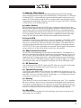
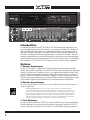
Introduction
The VTC Pro Audio V42 and V44 power amplifiers are designed and built to provide years
of trouble free performance. They weigh a comfortable (but solid) 42 pounds each, fit into
two rack spaces, and reproduce music with over 4000 Watts of headroom. The amplifiers are
fully protected from accidental short circuits and will drive reactive phase shifted loads with-
out difficulty. The design goal was to create an amplifier which does exactly what an ampli-
fier should do: reproduce music with great power, complete reliability, and uncompromising
signal fidelity. We think you will agree that the VTC Pro Audio V42 and V44 does exactly that.
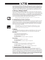
1. Balanced Inputs
Either XLR or two–circuit T.R.S. (Tip-Ring-Sleeve) Stereo 1/4-inch phone cords may be used.
Each channel’s XLR input is internally paralleled with its phone input (The TIP of the chan-
nel A phone input is connected to pin 2 of its XLR input, the ring is connected to pin 3, and
the Sleeve is connected to PIN 1). PIN 2 is in phase, PIN 3 is 180-degrees out-of-phase, and
PIN 1 is ground. It is recommended to use balanced lines for the best hum -free performance,
particularly when connecting multiple amplifier inputs together.
2. Unbalanced Inputs
Ordinary single circuit Standard 1/4-inch PHONE plugs may be used to connect
unbalanced signals.
NOTE: Such plugs effectively connect the ring terminal to sleeve ground, so they
work correctly. However, if you use a Stereo 1/4-inch PHONE plug on an unbal-
anced line, you MUST short the Ring terminal to the sleeve terminal; otherwise the
sensitivity will be 6dB lower than is specified! (The same applies to the XLR input: To
connect an unbalanced source via the XLR input, you must connect the signal to Pin
2 and ground both Pin 1 and Pin 3).
Power
V42
POWER AMPLIFIER
Protect
Power
-
0 0 0
-
0 0 0
-
21
-
3 0
-
1 5
-
1 8
-
6
-
12
-
9
-
3
dB
-
0 0 0
-
0 0 0
-
21
-
3 0
-
1 5
-
1 8
-
6
-
12
-
9
-
3
dB
Clip
Signal
Channel A
Clip
Signal
Channel B
Protect
Power
GND
LIFT
MODE
LIMITER
FILTER
DEFEAT
ENABLE
BRIDGE
STE REO
MONO
40Hz
20Hz
IN MONO AND BRIDGE MODES
INPUTS ARE IN PARALLEL
AMPLIFIER
INPUTS
A
B
WARNING: SHOCK HAZARD • DO NOT OPEN
AVIS: RISQUE DE CHOC • NE PAS OUVRIR
SPEAKON™ PIN CONFIGURATION
()
1+
1–
()
2+
2–
A
/
B
SINGLE CABLE OUTPUT
()
1+
1–
()
1+
1–
AB
TWO CABLES
MADE IN CANADA
()
1+
()
2+
BRIDGE CABLE*
*SPECIAL CABLE REQUIRED
STEREO: 2 OHMS MIN
BRIDGED: 4 OHMS MIN
CIRCUIT
BREAKER
Channel
B
A
Channel
A/B BRIDGED
WARNING: RISK OF HAZARDOUS ENERGY! SEE OPERATING MANUAL.
AVERTISSEMENT: ÉNERGIE ÉLECTRIQUE DANGEREUSE! VOIR LE CAHIER D'INSTRUCTION.
V 42
SPEAKER
OUTPUTS
MODEL TYPE: YS4020
A-Z1103A / 1v1
120VAC
60Hz
10A
230V
50Hz
5,0A
LR 21877

2
3. Remote Referencing
You can approach balanced performance with unbalanced sources by utilizing the re-
mote reference feature of the V42/V44. Connect a balanced cable to the V42/V44 just as
you would if you were running a balanced line. At the other end, connect Pin 3 and Pin 1
together, (or connect ring to sleeve if you are using a PHONE plug cable), and plug this
modified end into your unbalanced piece of equipment. This connection enables the V42/
V44’s input to look down the cable directly at the output jack of the unbalanced equipment.
Any hum voltage generated across the cable’s impedance will be attenuated by the common
mode rejection of the V42/V44.
4. Driving Multiple V42/V44’s
In large installations it is often desirable to operate many amplifiers in tandem. Since each chan-
nel’s XLR input is internally paralleled with its phone input, you may use the remaining input
jack as an output to the next amplifier. Obviously you will need both XLR to XLR and PHONE to
PHONE patch cords if you are going to tandem more than two amplifiers.
NOTE: These patch cords MUST be balanced whether the input signal is bal-
anced or unbalanced!
5. Ground Switch
Switching the ground switch on the rear panel will disconnect chassis ground from circuit
ground. Safety (earth) ground is still connected to the chassis. We do not recommend lifting the
ground strap unless you are experiencing problems with ground loop hum in multiple amplifier
setups where lifting the ground straps of all but one amplifier cures the hum problem.
CAUTION: Sometimes hum problems are an indication of improper AC wiring
somewhere else in your system. Don’t just doctor the symptom by lifting grounds.
Fix the cause by making sure that the proper electrical wiring safety regulations
have been adhered to.
6. Modes
The VTC Pro Audio V42/V44 can be configured for dual-MONO, STEREO or BRIDGED operation
via the rear panel MODE switch. The following is a description of each mode:
Mono Mode
• Channel A & B inputs are paralleled
• Each gain control adjusts the signal level for its respective channel
• Output signals are of equal phase.
• Two loads are driven.
• Loads are connected to the Speakon™ connectors on each channel.
Stereo Mode
• Two independent ampliers, Amp A and Amp B.
• Two loads are driven.
• Loads are connected to the Speakon™ connectors on each channel.
Bridge Mode
• Channel A & B inputs are paralleled. GAIN B control has no effect.
• Output signals are equal in amplitude but opposite in phase.
• One load is driven.
• The load is connected between the pins 1+ and 2+ on the Speakon™ connector on channel A.

3
7. Subsonic Filter Switch
The VTC Pro Audio V42/V44 features a specially designed subsonic filter which effectively
blocks potentially destructive energy in the band below 40 Hz. The filter provides a 12 dB/octave
skirt below 40 Hz. It is implemented with a two pole network designed to minimize phase shift
down to 40 Hz. We recommend using this filter in conjunction with some subwoofers and with
all high power full range cabinets. When the subsonic filter is disabled, the V42/V44 is flat (down
to 20 Hz) and rolls off at 12dB/Oct below that.
8. Limiter Switch
With the internal limiters activated, the V42/V44’s gain is continuously adjusted to fit the signal
within the available dynamic range. Occasional clipping is permitted. The limiters will not only help
to protect your system’s horns but will automatically make the best use of the available dynamic
headroom. With the limiters activated, all you need to do is turn up the signal level until you start
to see some clipping. The limiters will make sure that you are getting the maximum clean power
output at all times. Setting the switch to the IN position completely disables both limiters.
9. Protect LED
In the event of a shorted load or a load which is of too low an impedance for the amplifier to handle
the PROTECT LED will flash alternately on and off at about 3 second intervals. The sound may
come on at ½ second intervals. In this case, the fault is in the speakers or the speaker cables and
should be located and remedied. No reset of the V42/V44 is required to restore proper operation.
The PROTECT LED will stay on if the amplifier has overheated. Check the speaker load impedance
and any restrictions to air flow at the air intake or exhaust vents of the amplifier.
10. Short Circuit Protection
The V42/V44is fully protected against all possible passive load conditions. It can operate into a
dead short continuously without damage. (However, we don’t recommend that you short your V42/
V44 “just for fun.” Shorts do create a lot of stress on the output devices). The output stage uses a
unique triple slope VI-limiting scheme which is sophisticated enough to remain inert during tran-
sient currents in excess of 100 Amperes and phase angles of more than 45 degrees, yet is capable
of protecting the output stage from damage due to accidental short circuits and improper loads.
11. DC Protection
In the unlikely event of the V42/V44’s outputs going DC, a thyristor circuit will short the output
terminals and divert all potentially harmful currents away from your speakers.
12. Thermal Protection
In the unlikely event that the V42/V44 overheats, the signal will be sporadically cut off the
audio signal and the PROTECT LED will stay on. The V42/V44 is designed and tested to op-
erate under “worst case” conditions without shutting down, so if you experience a thermal
shut down you should check for blocked air flow.
13. Cooling
The fan draws air in from the front and expels hot air through the rear vents. This is compatible
with most installations. Since hot air rises, the heated air forcibly expelled from the back tends
to rise away from the equipment rack. This draws cool air from the floor upwards into the front
of the rack. In some cases where the rear of the rack is obstructed, it may be necessary to install
rack fans to aid cooling. If there are no obstructions, no secondary cooling is required.
14. Clip LEDs
The CLIP LEDs on the front panel will visibly indicate any signal excursion beyond the dy-
namic headroom of the amplifier.

4
15. Reliability
The V42/V44 is designed and manufactured by VTC Pro Audio. Each unit undergoes a thorough,
temperature cycled burn-in period, and each circuit is tested by both manual and sophisticated
computer controlled equipment which is capable of identifying any deviation from the design
center parameters. The design of the V42/V44 is conservative with respect to the power handling
capabilities of the output devices. The topology guarantees that thermal stress not secondary
breakdown will set the limits of operation; while the computer optimized heat dissipation system
insures that excessive thermal stress will not occur. VTC Pro Audio’s reputation as a manufac-
turer of reliable equipment will be further enhanced by the V42/V44.
The V42/V44 is not only suitable for use in both heavy duty touring sound reinforcement sys-
tems but also when high headroom and low distortion are needed to fully reproduce the dynamic
range and clarity of today’s CD recordings. It is built to survive grueling road conditions and
constant 2 ohm (4 ohm in the V44) operation. Its reliability in a fixed installation running 4 or 8
ohm studio monitors is without parallel.
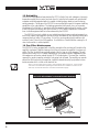
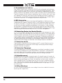
16. Fan Filter Maintenance
The V42/V44 is factory equipped with a fan filter mounted on the air-intake grill located on the
amplifier’s front panel. Regular cleaning of this filter will increase the amplifier’s long term reli-
ability. The filter should be removed and washed at the first sign of visible clogging. This will
typically occur every four to six weeks depending on use and environment. Replacement filters
are inexpensive and can be ordered through VTC Pro Audio dealers. The foam filter should be
removed if a regular inspection schedule is not going to be followed. The amplifier can operate
without the filter in place, but the amplifier should be cleaned internally by a qualified service
technician when dust is visible on the heatsink fins.
Note: In an unusually dusty location, without regular filter inspections, removing the
foam filter can extend the operating time before thermal shutdown could occur. At
that time, the internal heatsinks should be cleaned thoroughly.
VTC#8380
Foam Filter
VTC#8807
Mounting Screws
AIR FILTER REPLACEMENT and MAINTENANCE DIAGRAM

5
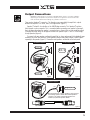
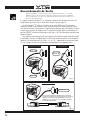
Output Connections
WARNING: When driven to full power in Bridge Mode. There is more than 100Vrms
appearing in the Speakon™ jack which represent a significant shock hazard. Due
care should be taken when making any speaker connections.
There are two Speakon™ connectors. The Speakons are connected to the amplier’s outputs
whether the amplifier is in stereo, mono, or bridge modes (figure 1).
Speakon™ output A also doubles as the A&B/Bridge connector. This Speakon™ contains
both channels on one connector. This is convenient when connecting one speaker to the ampli-
fier in bridge mode where the speaker is connected across the positives of each amplifier output.
Congure the mode switch for bridge and connect the speaker to pins +1 and +2 of the bridge /
bi-amp Speakon (figure 3).
To connect a bi-amp speaker, configure the amplifier for stereo and connect to the bridge/bi-amp
connector but use all four terminals in the Speakon connector which will connect A and B outputs
separately to the speaker (figure 2). Connection configurations are labeled on the back panel.
-
1 (N.C.)
-
2 (N.C.)
SPEAKER
OUTPUTS
Channel
B
A
Channel
A/B B
R
IDGED
STEREO: 2 OHMS MIN
BRIDGED: 4 OHMS MIN
A (+1,
-
1)
A (+1,
-
1)
B (+2,
-
2)
B (+1,
-
1)
SPEAKER
OUTPUTS
Channel
B
A
Channel
A/B B
R
IDGED
STEREO: 2 OHMS MIN
BRIDGED: 4 OHMS MIN
SPEAKER
OUTPUTS
Channel
B
A
Channel
A/B B
R
IDGED
STEREO: 2 OHMS MIN
BRIDGED: 4 OHMS MIN
Figure 3
Figure 1
Figure 2
1
+
1
-
2
+
2
-
1
+
1
-
2
+
2
-
N/C
N/C
N/C
N/C
Tw o Channel Configuration Bi Amp Configuration
Bridged Configuration
Note: A standard four conductor Speakon
TM
cable cannot be
used to bridge speaker cabinets with standard Speakon
TM
connectors. The output of channel B (+2) will short to
channel A (A-) inside the speaker cabinet!
Amplifier Side Speaker Cabinet Side
Bridged (+1, +2)

6
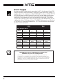
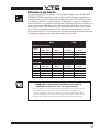
Power Output
All values are in WATTS. Measurements were made at the 0.1% distortion point. Some CON-
TINUOUS AVERAGE POWER measurements required line currents greater than 15 Amps. The
amplifier under test was plugged into an IDEAL POWER LINE consisting of a REGULATED 120
VAC RMS 60 Hz pure sine wave. Ordinary AC “wall outlet” lines will always exhibit varying
and unpredictable amounts of voltage sag. To produce objectively verifiable and accurate
specifications these unknown factors must be eliminated by using an ideal AC line. When
using an ordinary electrical outlet, it will usually be possible to get 2400 Watts when the V42
is bridged into 4 ohms (V44 bridges at 8 ohms). The BURST measurements use a 10mS burst
at 1 KHz with a 1/8 second pause between bursts. The 1 KHz burst represents the maximum
possible sine wave output power.
V42 V44
1KHz 1KHz 1KHz 1KHz
(ohms)
8 475 625 750 1200
4 750 1200 1200 2175
2 1200 2175 n/a n/a
1KHz 1KHz 1KHz 1KHz
(ohms)
8 1500 2400 2400 4350
4 2400 4350 n/a n/a
2 n/a n/a n/a n/a
Both Channels Driven
Load
Cont. Avg. Burst Cont. Avg. Burst
2 ohm Mode 2 ohm Mode 4 ohm Mode 4 ohm Mode
Load
Cont. Avg. Burst Cont. Avg. Burst
2 ohm Mode 2 ohm Mode 4 ohm Mode 4 ohm Mode
Bridge Mod
CAUTION: The VTC Pro Audio V42/V44 can deliver over
2400 Watts of power into a bridged load!!NS
VTC Pro Audio is not responsible for any damage which may result as a
consequence of exceeding such a speaker’s power handling capability. VTC
Pro Audio’s two year unconditional warranty does not cover any consequential
damages to non-VTC Pro Audio equipment. Please consider these facts care-
fully before you choose to run your VTC V42/V44!

7
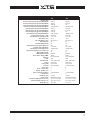
Specifications
V42V44
Amplifier class
HH
Coninuous Average Power @ 8 ohms BCD (Watts)
)2x( 057)2x( 574
Coninuous Average Power @ 4 ohms BCD (Watts)
)2x( 0021)2x( 057
Coninuous Average Power @ 2 ohms BCD (Watts)
1200 (x2) NA
Continuous Average Power Bridged BCD (Watts)
2400 @ 4 ohms 2400 @ 8 ohms
Burst Average Power @ 8 ohms BCD (Watts)
)2x( 0021)2x( 526
Burst Average Power @ 4 ohms BCD (Watts)
1200 (x2) 2175 (x2)
Burst Average Power @ 2 ohms BCD (Watts)
2175 (x2) NA
Burst Average Power Bridged BCD (Watts)
4350 @ 4 ohms 4350 @ 8 ohms
Frequency Response (Hz, +/- 1dB)
20-20,00020-20,000
Hum and Noise (un / Aweighted -dB)
-103 / -106 -103 / -106
THD -1kHz- 4 ohms
%10.0% 10.0
THD - 20Hz-20kHz, 4 ohms
less than 0.1% less than 0.1%
Slew Rate (V/uS)
5252
Slew Rate Bridged (V/uS)
0505
Damping Factor (30 Hz - 400 Hz @ 8 ohms)
006006
Crosstalk (1kHz / 20Hz-20kHz)
-75 / -60 dB -75 / -60 dB
Input Impedance - Bal/Unbal (ohms)
20,000/10,000 20,000/10,000
Input Sensitivity (Vrms) For Full Power Out
V 7.1V 2.1
Max Voltage Gain (dB)
2323
CMRR @ 60Hz (min/typ)
Bd 65/84Bd 65/84
Stereo / Mono / Bridge (S/M/B)
B/M/SB/M/S
Protection
DC,Load,Thermal DC,Load,Thermal
Limiter
kaePkaeP
High Pass Filter
40Hz, 12dB Octave40Hz, 12dB Octave
Cooling
Internal FanInternal Fan
Cooling Path
Front to Rear Front to Rear
Fan Filter
User Serviceable User Serviceable
Inputs - XLR
22
Inputs - 1/4-inch Jacks
22
Outputs - Speakon 4-pin
22
Power Consumption (typ/max)
1130/1800 Watts 1130/1800 Watts
Rack Spaces
22
Transformer Type
ladioroTladioroT
Exterior Finish
Baked, Black Painted Baked, Black Painted
Dimensions (DWH /D fm ears, inches)
19 x 17.3 x 3.5 x 16.219 x 17.3 x 3.5 x 16.2
Dimensions (DWH /D fm ears, cm)
48.3 x 43.9 x 8.9 x 41 48.3 x 43.9 x 8.9 x 41
Weight (lbs / kg)
40.5 / 18.4 43.5 / 19.8
Page is loading ...
Page is loading ...
Page is loading ...
Page is loading ...
Page is loading ...
Page is loading ...
Page is loading ...

Limited Warranty
Yorkville’s two-year conditional warranty on this product is transferable and
does not require registration with Yorkville Sound or your dealer. If this
product should fail within two years of the original purchase date due to a
manufacturing defect, simply return it to your Yorkville Dealer with original
proof of purchase and it will be repaired free of charge.
Freight charges, consequential damages, weather damage, damage as a
result of improper installation, damages due to exposure to extreme humidity,
accident or natural disaster are excluded under the terms of this warranty.
See your Yorkville dealer for more details. Warranty valid only in Canada and
the United States
Garantie Limitée
La protection qu’offre cette garantie limitée de deux ans est transférable. Il n’est
pas nécessaire de faire enregistrer votre nom. Si durant les deux années qui
suivent la date d’achat originale, un problème causé par un défaut de fabrication
survient, nous ferons la réparation de l’appareil gratuitement. Retournez
simplement l’appareil défectueux à votre vendeur autorisé avec la preuve d’achat
originale et l’appareil sera réparé gratuitement. Les frais de port et de
manutention ainsi que les dommages indirects ou dommages causés par
désastres naturels, extrême humidité ou mauvaise installation ne sont pas
couverts par cette garantie. Voir votre marchand Yorkville pour plus de détails.
Cette garantie n’est valide qu’au Canada et aux États Unis d’Amérique.
www.vtcproaudio.com
Yorkville Sound
550 Granite Court
Pickering, Ontario
L1W-3Y8 CANADA
Yorkville Sound Inc.
4625 Witmer Industrial Estate
Niagara Falls, New Yo rk
14305 USA
Canada
Voice: (905) 837-8481
Fax: (905) 837-8746
U.S.A.
Voice: (716) 297-2920
Fax: (716) 297-3689
Two Year Warranty
Manual-Owners-CMS442IO-00-1v0 • July 17/2008

www.vtcproaudio.com
U.S.A.
Yorkville Sound Inc.
4625 Witmer Industrial Estate
Niagara Falls, New Yo rk
14305 USA
Voice: (716) 297-2920
Fax: (716) 297-3689
CANADA
Yorkville Sound
550 Granite Court
Pickering, Ontario
L1W-3Y8 CANADA
Voice: (905) 837-8481
Fax: (905) 837-8746
Manual-Owners-V42-V44-00-1v0 • April 14, 2009
-
 1
1
-
 2
2
-
 3
3
-
 4
4
-
 5
5
-
 6
6
-
 7
7
-
 8
8
-
 9
9
-
 10
10
-
 11
11
-
 12
12
-
 13
13
-
 14
14
-
 15
15
-
 16
16
-
 17
17
-
 18
18


VTC Pro Audio V42 Owner's manual
- Category
- Audio amplifiers
- Type
- Owner's manual
- This manual is also suitable for
Ask a question and I''ll find the answer in the document
Finding information in a document is now easier with AI
in other languages


Other documents
-
YORKVILLE AP4K Owner's manual
-
Gemini GXA 750 User manual
-
 YORKVILLE AP6040 Owner's manual
-
HK Audio VC 2400 User manual
-
Yorkville Sound AP6020AP6020 User manual
-
Biamp 1200-2400 Operation User manual
-
 YORKVILLE V22 Owner's manual
-
HK Audio VX Series User manual
-
 YORKVILLE AP4040 - SERVICE User manual
-
Crown Pulse Series User manual


