Mode AVIC F220 Owner's manual

Category
Network antennas
Type
Owner's manual

This manual is also suitable for

INSTALLATION MANUAL
MANUEL DINSTALLATION
HIDE-AWAY NAVIGATION SYSTEM
SISTEMA DE NAVEGACIÓN OCULTO
VERBORGENES NAVIGATIONSSYSTEM
MODULE DE NAVIGATION DEPORTE ETAMOVIBLE
SISTEMA DI NAVIGAZIONE A SCOMPARSA
NAVIGATIESYSTEEM VOOR VERBORGEN INBOUW
AVIC-F220
English NederlandsItalianoFrançaisDeutschEspañol
IMPORTANT INFORMATION
ABOUT YOUR NEW NAVIGATION SYSTEM
AND THIS MANUAL 3
IMPORTANT SAFEGUARDS
PLEASE READ ALL OF THESE
INSTRUCTIONS REGARDING YOUR
NAVIGATION SYSTEM AND RETAIN THEM
FOR FUTURE REFERENCE 4
Connecting the system
Precautions before connecting the
system 5
Before installing this product 5
To prevent damage 5
Parts supplied 6
Connecting the system 7
Connecting the power cord 8
Tying the cables 8
Replacing the fuse 9
Installation
Precautions before installation 10
To guard against electromagnetic
interference 10
Before installing 10
Installing the navigation system 11
Installation notes 11
Parts supplied 12
Before installing the base unit 12
Installing with self-tapping screws 13
Installing with the hook and loop
fastener 13
Attaching the detachable device 14
Installing the GPS aerial 15
Installation notes 15
Parts supplied 15
When installing the aerial inside the
vehicle (on the dashboard or rear
shelf) 16
Installing the RDS-TMC tuner 17
Parts supplied 17
Wiring the external aerial 17
Mounting the RDS-TMC tuner 17
After installation
After installing this navigation system 18
Contents
Engb
2
ABOUT YOUR NEW
NAVIGATION SYSTEM AND
THIS MANUAL
! The navigation features of this product are
intended solely to aid you in the operation
of your vehicle. It is not a substitute for
your attentiveness, judgement and care
when driving.
! Never use this navigation system to route
to hospitals, police stations, or similar facil-
ities in an emergency. Please call the ap-
propriate emergency number.
! Do not operate this navigation system if
doing so in any way will divert your atten-
tion from the safe operation of your vehicle.
Traffic restrictions and advisories currently
in force should always take precedence
over guidance given by this product. Al-
ways obey current traffic restrictions, even
if this product provides contrary advice.
! This manual explains how to install this na-
vigation system in your vehicle. Operation
of this navigation system is explained in
the separate manuals for the navigation
system.
! Do not install this product where it may (i)
obstruct the drivers vision, (ii) impair the
performance of any of the vehicles operat-
ing systems of safety features, including
airbags, hazard lamp buttons or (iii) impair
the drivers ability to safely operate the vehi-
cle. In some cases, it may not be possible
to install this product because of the vehi-
cle type or the shape of the vehicle inter-
ior.
Engb
3
English
Section
01
IMPORTANT INFORMATION
WARNING
Pioneer does not recommend that you install
your navigation system yourself. We recom-
mend that only authorised Pioneer service
personnel, who have special training and ex-
perience in mobile electronics, set up and in-
stall this product. NEVER SERVICE THIS
PRODUCT YOURSELF. Installing or servi-
cing this product and its connecting cables
may expose you to the risk of electric shock
or other hazards, and can cause damage to
the navigation system that is not covered by
warranty.
PLEASE READ ALL OF THESE
INSTRUCTIONS REGARDING
YOUR NAVIGATION SYSTEM
AND RETAIN THEM FOR
FUTURE REFERENCE
1 Read this manual fully and carefully before in-
stalling your navigation system.
2 Keep this manual handy for future reference.
3 Pay close attention to all warnings in this
manual and follow the instructions carefully.
4 This navigation system may in certain circum-
stances display erroneous information regard-
ing the position of your vehicle, the distance
of objects shown on the screen, and compass
directions. In addition, the system has certain
limitations, including the inability to identify
one-way streets, temporary traffic restrictions
and potentially unsafe driving areas. Please
exercise your own judgement in the light of
actual driving conditions.
5 As with any accessory in your vehicles inter-
ior, the navigation system should not divert
your attention from the safe operation of your
vehicle. If you experience difficulty in operat-
ing the system or reading the display, please
make adjustments while safely parked.
6 Please remember to wear your seat belt at all
times while operating your vehicle. If you are
ever in an accident, your injuries can be con-
siderably more severe if your seat belt is not
properly fastened.
7 Certain country and government laws may
prohibit or restrict the placement and use of
this system in your vehicle. Please comply
with all applicable laws and regulations re-
garding the use, installation and operation of
your navigation system.
Engb
4
Section
02
IMPORTANT SAFEGUARDS
Precautions before
connecting the system
CAUTION
! If you decide to perform the installation
yourself, and have special training and ex-
perience in the mobile electronics instal-
lations, please carefully follow all of the
steps in the installation manual.
! Secure all wiring with cable clamps or
electrical tape. Do not allow any bare wir-
ing to remain exposed.
! Do not directly connect the yellow lead of
this product to the vehicle battery. If the
lead is directly connected to the battery,
engine vibration may eventually cause
the insulation to fail at the point where
the wire passes from the passenger com-
partment into the engine compartment. If
the yellow leads insulation tears as a re-
sult of contact with metal parts, short-cir-
cuiting can occur, resulting in
considerable danger.
! It is extremely dangerous to allow the
cables to become wound around the steer-
ing column or gearstick. Be sure to install
this product, its cables, and wiring away
in such a way that they will not obstruct
or hinder driving.
! Make sure that the cables and wires are
routed and secured so they will not inter-
fere with or become caught in any of the
vehicles moving parts, especially the
steering wheel, gearstick, handbrake, slid-
ing seat tracks, doors, or any of the vehi-
cles controls.
! Do not route wires where they will be ex-
posed to high temperatures. If the insula-
tion heats up, wires may become
damaged, resulting in a short circuit or
malfunction and permanent damage to
the product.
! Do not cut the GPS aerial cable to shorten
it or use an extension to make it longer.
Altering the aerial cable could result in a
short circuit or malfunction.
! Do not shorten any leads. If you do, the
protection circuit (fuse holder, fuse resis-
tor or filter, etc.) may fail to work properly.
! Never feed power to other electronic pro-
ducts by cutting the insulation of the
power supply lead of the navigation sys-
tem and tapping into the lead. The current
capacity of the lead will be exceeded,
causing overheating.
! The black lead is earth. Please earth this
lead separately from the earth of high-cur-
rent products such as power amps. Do not
earth more than one product together
with the earth from another product. For
example, you must separately earth any
amp unit away from the earth of this navi-
gation system. Connecting earths to-
gether can cause a fire and/or damage the
products if their earths became
detached.
Before installing this product
! Use this unit with a 12-volt battery and ne-
gative earthing only. Failure to do so may
result in a fire or malfunction.
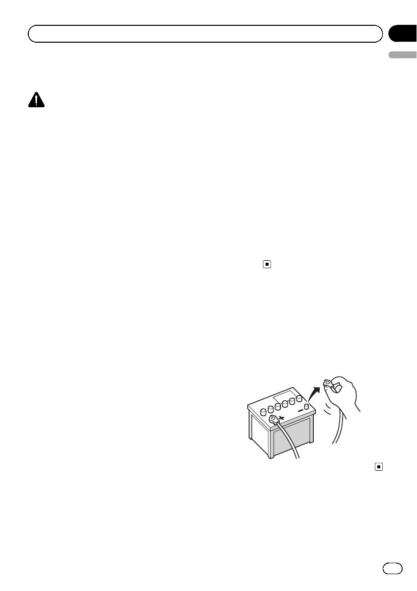
! To avoid shorts in the electrical system, be
sure to disconnect the () battery cable be-
fore beginning installation.
To prevent damage
! When disconnecting a connector, pull the
connector itself. Do not pull the lead, as
you may pull it out of the connector.
Engb
5
English
Section
03
Connecting the system
! Attach the connectors of the same colour
to the corresponding coloured port, i.e.,
blue connector to the blue port, black to
black, etc.
Parts supplied
Detachable device Base unit
Power cord RDS-TMC tuner
26-pin cable GPS aerial
External aerial Lock tie
Engb
6
Section
03
Connecting the system
We recommend connecting the supplied external aerial. Connect the aerial plug of your vehicle to the AV receiver di-
rectly (Fig. 1).
If you do not use the supplied external aerial in order to split radio signal between this product and the built-in tuner of
the AV receiver (Fig. 2), the radio sensitivity of the AV receiver may decrease.
26-pin cable (supplied)
3.55 m
2 m
GPS aerial
Green
Yellow
Base unit
RDS-TMC tuner
(supplied)
Not used.
Expansion port
30 cm
1 m
30 cm
AV receiver
Aerial jack of AV receiver
External aerial (supplied)
Aerial jack
Vehicle aerial
For more details about the wiring, refer to Wiring the external aerial on page 17.
(Fig. 1)
RDS-TMC tuner
AV receiver
Aerial jack of AV receiver
Vehicle aerial
Aerial jack
Aerial plug
(Fig. 2)
Note
The terminal form of the 26-pin cable may differ
depending on the terminal type of the AV receiver.
For details of connection, refer to the installation
manual supplied with the AV receiver.
Engb
7
English
Section
03
Connecting the system
Connecting the power cord
Yellow
To terminal always supplied
with power regardless of
ignition switch position.
Black (earth)
To vehicle (metal) body.
Power cord
Base unit
Fuse holder
Tying the cables
Tie loose cables in a bundle to prevent the
cables breaking.
% Tie loose cables with the lock tie.
4 cm to 8 cm
Leave enough slack part between each terminal and
tying part.
4 cm to 8 cm
Engb
8
Section
03
Connecting the system
Replacing the fuse
WARNING
! When replacing the fuse, be sure to use one
with the same rating.
! Keep the removed fuse out of the reach of
small children to prevent them from acciden-
tally swallowing it.
% Rotate in the clockwise direction to de-
tach the cap of the fuse holder.
Remove the fuse holder cap slowly so the fuse
does not pop out.
Fuse holder
Fuse (3.15 A, 250 V)
Engb
9
English
Section
03
Connecting the system
Precautions before
installation
CAUTION
! Never install this product in places where,
or in a manner that:
It could injure the driver or passengers
if the vehicle stops suddenly.
It may interfere with the drivers opera-
tion of the vehicle, such as on the floor
in front of the drivers seat, or close to
the steering wheel or gearstick.
! Make sure there is nothing behind the
dashboard or panelling when drilling
holes in them. Be careful not to damage
fuel lines, brake lines, electronic compo-
nents, communication wires or power
cables.
! When using screws, do not allow them to
come into contact with any electrical lead.
Vibration may damage wires or insulation,
leading to a short circuit or other damage
to the vehicle.
! To ensure proper installation, use the sup-
plied parts in the manner specified. If any
parts other than the supplied ones are
used, they may damage internal parts of
this product or they may work loose and
the product may become detached.
! It is extremely dangerous to allow the
cables to become wound around the steer-
ing column or gearstick. Be sure to install
this product, its cables, and wiring away
in such a way that they will not obstruct
or hinder driving.
! Make sure that leads cannot get caught in
a door or the sliding mechanism of a seat,
resulting in a short circuit.
! Please confirm the proper function of
your vehicles other equipment following
installation of the navigation system.
! Do not install this navigation system
where it may (i) obstruct the drivers vi-
sion, (ii) impair the performance of any of
the vehicles operating systems or safety
features, including airbags, hazard lamp
buttons or (iii) impair the drivers ability
to safely operate the vehicle.
! Never install the navigation system in
front of or next to the place in the dash,
door, or pillar from which one of your vehi-
cles airbags would deploy. Please refer to
your vehicles owners manual for refer-
ence to the deployment area of the frontal
airbags.
To guard against
electromagnetic interference
In order to prevent interference, set the follow-
ing items as far as possible from this naviga-
tion system, other cables or leads:
! FM, MW/LW aerial and its lead
! GPS aerial and its lead
In addition you should lay or route each aerial
lead as far as possible from other aerial leads.
Do not bind them together, lay or route them
together, or cross them. Such electromagnetic
noise will increase the potential for errors in
the location display.
Before installing
! Consult with your nearest dealer if installa-
tion requires the drilling of holes or other
modifications of the vehicle.
! Before making a final installation of this
product, temporarily connect the wiring to
confirm that the connections are correct
and the system works properly.
Engb
10
Section
04
Installation
Installing the navigation
system
! We recommend installing the system inside
the glove box or armrest.
! Install the navigation system in a level, fix-
able location.
Installation notes
! Do not install the navigation system in
places subject to high temperatures or hu-
midity, such as:
Places close to a heater, vent or air con-
ditioner.
Places exposed to direct sunlight, such
as on top of the dashboard.
Places that may be exposed to rain,
such as close to the door or on the vehi-
cles floor.
! Do not install the navigation system near
the drivers seat. Doing so may cause an
accident or injury should the detachable
device fall to the floor and become lodged
under the accelerator or brake pedal.
! When using screws, do not attach it to a
curved surface. Attaching the unit to a
curved surface may bend the base unit and
prevent attaching/detaching the detach-
able device.
! When installing the navigation system in-
side a glove compartment or similar loca-
tion, make sure the cables and wires do not
get pinched or interfere with the any open/
close mechanism or other moving parts.
Repeated pressure on the cables or wires
may cause the insulation to fail and cause
a short circuit.
! Do not install this navigation system where
the detachable device could interfere with
vehicle operation or bump other objects
when attaching or detaching the device.
Make sure to allow enough space for at-
taching/detaching the detachable device
to/from the base unit.
Base unit
7 cm
5 cm
5 cm
Base unit Detachable device
7 cm
5 cm
Surface of the glove box
or similar location
Engb
11
English
Section
04
Installation
Parts supplied
Detachable device Base unit
Self-tapping screw
(4 mm × 15 mm)
(4 pcs.)
Hook and loop
fasteners
(2 pcs.)
Before installing the base unit
1 Press the Detach button to release the
detachable device.
2 Gently grip both sides of the detach-
able device and slowly pull it out.
p Take care not to drop the detachable device
and protect it from contact with water or
other fluids to prevent permanent damage.
p Do not forcibly pull the detachable device
from the base unit, as doing so may da-
mage the connector.
Engb
12
Section
04
Installation
Installing with self-tapping screws
% Secure it firmly using the self-tapping
screws.
Self-tapping screw Base unit
Surface of the glove
box or similar location
Drill 2 mm to 2.5 mm dia-
metre holes.
Installing with the hook and
loop fastener
1 Thoroughly wipe off both surfaces be-
fore affixing the hook and loop fastener.
2 Peel off the protective sheet and attach
the hook and loop fastener.
Protective sheet Base unit
3 Decide on the installation position.
4 Peel off the other protective sheet and
install the base unit on the surface of the
glove box or similar location.
Base unit
Surface of the glove box
or similar location
Protective sheet
Engb
13
English
Section
04
Installation
Attaching the detachable device
1 Slide the detachable device all the way
into the base unit.
Make sure that the detachable device is se-
curely connected to the base unit terminal.
Connecting terminals
2 Press the centre of the front of the de-
tachable device until you hear a click.
If you fail to successfully attach the detach-
able device to the base unit, try again but be
careful not to force it as the unit could be da-
maged.
Engb
14
Section
04
Installation
Installing the GPS aerial
CAUTION
Do not cut the GPS aerial lead to shorten it
or use an extension to make it longer. Alter-
ing the aerial cable could result in a short cir-
cuit or malfunction and permanent damage
to the navigation system.
Installation notes
! The aerial should be installed on a level sur-
face where radio waves will be blocked as
little as possible. Radio waves cannot be re-
ceived by the aerial if reception from the sa-
tellite is blocked.
Dashboard Rear shelf
! When installing the GPS aerial inside the
vehicle, be sure to use the metal sheet pro-
vided with your system. If this is not used,
the reception sensitivity will be poor.
! Do not cut the accessory metal sheet. This
would reduce the sensitivity of the GPS aer-
ial.
! Take care not to pull the aerial lead when
removing the GPS aerial. The magnet at-
tached to the aerial is very powerful, and
the lead may become detached.
! Do not paint the GPS aerial, as this may af-
fect its performance.
Parts supplied
GPS aerial Metal sheet
Engb
15
English
Section
04
Installation
When installing the aerial inside the vehicle (on the dashboard or
rear shelf)
WARNING
Do not install the GPS aerial over any sen-
sors or vents on the dashboard of the vehicle,
as doing so may interfere with the proper
functioning of such sensors or vents and may
compromise the ability of the metal sheet
under the GPS aerial to properly and se-
curely affix to the dashboard.
Affix the metal sheet on as level a surface as
possible where the GPS aerial faces the win-
dow. Place the GPS aerial on the metal sheet.
(The GPS aerial is fastened with its magnet.)
The metal sheet contains a
strong adhesive which may
leave a mark on the surface if
it is removed.
Note
Clamps
Use separately sold clamps
to secure the lead where necessary
inside the vehicle.
GPS aerial
Metal sheet
Peel off the protective sheet
on the rear.
Make sure the surface is
free of moisture, dust,
grime, oil, etc., before
affixing the metal sheet.
Notes
! When attaching the metal sheet, do not cut
it into small pieces.
! Some models use window glass that does
not allow signals from GPS satellites to
pass through. On such models, install the
GPS aerial on the outside of the vehicle.
Engb
16
Section
04
Installation
Installing the RDS-TMC tuner
Parts supplied
External aerial RDS-TMC tuner
Wiring the external aerial
Over 10 cm 35 cm to 75 cm
Mounting the RDS-TMC tuner
1 Decide on the installation position.
2 Attach the tuner using separately sold
adhesive tapes.
RDS-TMC tuner
Adhesive tape (sold separately)
Engb
17
English
Section
04
Installation
After installing this
navigation system
CAUTION
After installing this navigation system, be
sure to check at a safe place that the vehicle
is performing normally.
It may take a few minutes to start up the navi-
gation system when you start up the system
for the first time or the outside temperature is
not within the charging range. Wait until the
battery charging starts.
1 Reconnect the negative () terminal of
the vehicles battery.
First, double-check that all connections are
correct and that this product is installed cor-
rectly. Reassemble all vehicle components
that you previously removed. Then reconnect
the negative () cable to the negative ( ) term-
inal of the battery.
2 Start the engine.
3 Press the RESET button.
Press the RESET button on the navigation unit
with a pointed object such as the tip of a pen.
RESET button
After a short pause, the navigation screen re-
turns.
p If the navigation screen does not return
after a while, press the MODE button of the
AV receiver to switch the screen.
4 Make the following settings.
= For details concerning operations, refer to
Operation Manual.
1 Set the language.
2 Drive an unobstructed road until the GPS
starts receiving the signal normally.
3 Make some necessary adjustments.
! Setting the time
! Change other settings as you prefer
Engb
18
Section
05
After installation
Technische Hotline der
Pioneer Electronics Deutschland GmbH
TEL: 02154/913-333
PIONEER CORPORATION
1-1, Shin-ogura, Saiwai-ku, Kawasaki-shi,
Kanagawa 212-0031, JAPAN
PIONEER ELECTRONICS (USA) INC.
P.O. Box 1540, Long Beach, California 90801-1540, U.S.A.
TEL: (800) 421-1404
PIONEER EUROPE NV
Haven 1087, Keetberglaan 1, B-9120 Melsele, Belgium/Belgique
TEL: (0) 3/570.05.11
Published by Pioneer Corporation.
Copyright © 2010 by Pioneer Corporation.
All rights reserved.
Publié par Pioneer Corporation.
Copyright © 2010 par Pioneer
Corporation.
Tous droits réservés.
Printed in China
Imprimé en Chine
<CZR5375-A> EU
<KMZZX> <10C00000>
  • Page 1 1
  • Page 2 2
  • Page 3 3
  • Page 4 4
  • Page 5 5
  • Page 6 6
  • Page 7 7
  • Page 8 8
  • Page 9 9
  • Page 10 10
  • Page 11 11
  • Page 12 12
  • Page 13 13
  • Page 14 14
  • Page 15 15
  • Page 16 16
  • Page 17 17
  • Page 18 18
  • Page 19 19
  • Page 20 20
  • Page 21 21
  • Page 22 22
  • Page 23 23
  • Page 24 24
  • Page 25 25
  • Page 26 26
  • Page 27 27
  • Page 28 28
  • Page 29 29
  • Page 30 30
  • Page 31 31
  • Page 32 32
  • Page 33 33
  • Page 34 34
  • Page 35 35
  • Page 36 36
  • Page 37 37
  • Page 38 38
  • Page 39 39
  • Page 40 40
  • Page 41 41
  • Page 42 42
  • Page 43 43
  • Page 44 44
  • Page 45 45
  • Page 46 46
  • Page 47 47
  • Page 48 48
  • Page 49 49
  • Page 50 50
  • Page 51 51
  • Page 52 52
  • Page 53 53
  • Page 54 54
  • Page 55 55
  • Page 56 56
  • Page 57 57
  • Page 58 58
  • Page 59 59
  • Page 60 60
  • Page 61 61
  • Page 62 62
  • Page 63 63
  • Page 64 64
  • Page 65 65
  • Page 66 66
  • Page 67 67
  • Page 68 68
  • Page 69 69
  • Page 70 70
  • Page 71 71
  • Page 72 72
  • Page 73 73
  • Page 74 74
  • Page 75 75
  • Page 76 76
  • Page 77 77
  • Page 78 78
  • Page 79 79
  • Page 80 80
  • Page 81 81
  • Page 82 82
  • Page 83 83
  • Page 84 84
  • Page 85 85
  • Page 86 86
  • Page 87 87
  • Page 88 88
  • Page 89 89
  • Page 90 90
  • Page 91 91
  • Page 92 92
  • Page 93 93
  • Page 94 94
  • Page 95 95
  • Page 96 96
  • Page 97 97
  • Page 98 98
  • Page 99 99
  • Page 100 100
  • Page 101 101
  • Page 102 102
  • Page 103 103
  • Page 104 104
  • Page 105 105
  • Page 106 106
  • Page 107 107
  • Page 108 108
  • Page 109 109
  • Page 110 110
  • Page 111 111
  • Page 112 112

Mode AVIC F220 Owner's manual

Category
Network antennas
Type
Owner's manual
This manual is also suitable for

Ask a question and I''ll find the answer in the document

Finding information in a document is now easier with AI