Craftsman 316711191 Owner's manual
- Category
- Grass trimmers
- Type
- Owner's manual
This manual is also suitable for

Operator's Manual
2-Cycle
WEEDWACKER® GAS TRIMMER
Model No. 316.711191
CAUTION: Before using this product,
read this manuaJ and follow aJl its Safety
RuJes and Operating instructions.
* SAFETY
* ASSEMBLY
* OPERATION
* MAINTENANCE
. ESPANOL, R 19
Sears Brands Management Corporation, Hoffman Estates, IL 60179 U.S.A.
Visit our website: www.craftsman.corn
769-10237 / 00 09/14

TABLEOFCONTENTS
Safety............................................... 2
Warranty............................................. 5
KnowYourUnit........................................ 6
Specifications......................................... 6
Assembly............................................. 7
OilandFuel........................................... 9
StartingandStopping.................................. 10
Operation............................................ 11
Maintenance......................................... 13
CleaningandStorage.................................. 16
Troubleshooting....................................... 17
RepairProtectionAgreements........................... 18
ServiceNumbers.............................. BackCover
Allinformation,illustrationsandspecificationsinthismanualarebased
onthelatestproductinformationavailableatthetimeofprinting.We
reservetherighttomakechangesatanytimewithoutnotice.
©SeamBrands,LLC
Thepurposeofsafetysymbolsistoattractyourattentionto
possibledangers.Thesafetysymbols,andtheirexplanations,
deserveyourcarefulattentionandunderstanding.Thesafety
warningsdonotbythemselveseliminateanydanger.The
instructionsorwarningstheygivearenotsubstitutesforproper
accidentpreventionmeasures.
iSYMBOL MEANING
•
DANGER. Signals an EXTREME hazard.
Failure to obey a safety DANGER signal WILL result in
serious injury or death to yourself or to others.
WAR NING: Signals a SERIOUS hazard.
Failure to obey a safety WARNING signal CAN result in
serious injury to yourself or to others.
.
CAUTION. Signals a MODERATE hazard.
Failure to obey a safety CAUTION signal MAY result in
property damage or injury to yourself or to others.
NOTE: Advises you of information or instructions vital to the
operation or maintenance of the equipment.
SPARK ARRESTOR NOTE
NOTE: For users on U.S. Forest Land and in the states of
California, Maine, Oregon and Washington. All U.S. Forest Land
and the state of California (Public Resources Codes 4442 and
4443), Oregon and Washington require, by law that certain internal
combustion engines operated on forest brush and/or grass-covered
areas be equipped with a spark arrestor, maintained in effective
working order, or the engine be constructed, equipped and
maintained for the prevention of fire. Check with your state or local
authorities for regulations pertaining to these requirements. Failure
to follow these requirements could subject you to liability or a fine.
This unit is factory equipped with a spark arrestor, if it requires
replacement, contact a Sears Parts & Repair Service Center to
install the appropriate muffler assembly.
_ CALIFORNIA PROPOSiTiON 65
WARNING: This product contains a chemical
known to the state of California to cause cancer, birth defects
or other reproductive harm.
Read the operator's manual and follow all warnings and safety
instructions. Failure to do so can result in serious injury to the
operator and/or bystanders.

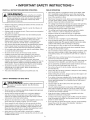
• iMPORTANT SAFETY iNSTRUCTiONS •
READ ALL iNSTRUCTiONS BEFORE OPERATING
m
WARNING. When using the unit, all safety
rules must be followed. Please read these instructions
before operating the unit in order to ensure the safety of
the operator and any bystanders. Please keep these
instructions for later use.
• Read the instructions carefully. Be familiar with the controls and
proper use of the unit.
Do not operate this unit when tired, ill or under the influence of
alcohol, drugs or medication.
Children must not operate the unit. Teens must be accompanied
and guided by an adult.
All guards and safety attachments must be installed properly
before operating the unit.
Inspect the unit before use. Replace damaged parts. Check for
fuel leaks. Make sure all fasteners are in place and secure.
Replace parts that are cracked, chipped, or damaged in any
way. Do not operate the unit with loose or damaged parts.
Only use the trimming line described in the Specifications section
of this manual. Never use metal-reinforced line, wire, chain or
rope. These can break off and become dangerous projectiles.
Do not replace the cutting head with rigid or metal blades. Doing
so could result in serious injury.
Be aware of risk of injury to the head, hands and feet.
Carefully inspect the area before starting the unit. Remove
rocks, broken glass, nails, wire, string and other objects that
may be thrown or become entangled with the unit.
Clear the area of children, bystanders and pets; keep them
outside a 50-foot (15 m) radius, at a minimum. Even then, they are
still at risk from thrown objects. Encourage bystanders to wear
eye protection. Ifyou are approached, stop the unit immediately.
Squeeze the throttle control and check that it returns
automatically to the idle position. Make all adjustments or
repairs before using the unit.
This unit is intended for occasional, household use only.
SAFETY WARNINGS FOR GAS UNITS
WARNING: Gasoline is highly flammable and
its vapors can explode if ignited. Take the following
precautions:
Store fuel only in containers specifically designed and approved
for the storage of such materials.
Always stop the engine and allow it to cool before filling the
tank. Never remove the fuel tank cap or add fuel when the
engine is hot. Always loosen the fuel tank cap slowly to relieve
any pressure in the tank before fueling.
Always mix and add fuel in a clean, well-ventilated outdoor area
where there are no sparks or flames. DO NOT smoke.
Never operate the unit without the fuel cap securely in place.
Avoid creating a source of ignition for spilled fuel. Wipe up any
spilled fuel from the unit immediately, before starting the unit.
Move the unit at least 30 ft. (9.1 m) from the fueling source and
site before starting the engine. DO NOT smoke.
Never start or run the unit inside a closed room or building.
Breathing exhaust fumes can kill. Operate this unit only in a well
ventilated outdoor area.
3
WHILE OPERATING
Wear safety glasses or goggles that meet current ANSi / ISEA
Z87.1 standards and are marked as such. Wear ear/hearing
protection when operating this unit. Wear a face mask or dust
mask if the operation is dusty.
Wear heavy long pants, boots, gloves and a long sleeve shirt. Do
not wear loose clothing, jewelry, short pants, sandals or go
barefoot. Secure hair above shoulder level.
The cutting head shield must always be in place while operating
the unit. Do not operate the unit without both trimming lines
extended and the proper line installed. Do not extend the
trimming line beyond the length of the shield.
The cutting head should remain stationary when the engine
idles. If it does not, refer to Adjusting the Idle Speed.
Adjust the handle to provide the best grip, if applicable.
Make sure the attachment is not in contact with anything before
starting the unit.
Use the unit only in daylight or good artificial light.
Avoid accidental starting. Be in the starting position whenever
pulling the starter rope. The operator and unit must be in a stable
position while starting. Refer to Starting and Stopping.
Use the right tool. Only use this tool for its intended purpose.
Always hold the unit with both hands when operating. Keep a
firm grip on both handles or grips.
Do not overreach. Always keep proper footing and balance. Take
extra care when working on stairs, steep slopes or inclines. To
avoid serious injury, do not operate the unit while on a ladder or
a roof.
Keep hands, face, and feet away from all moving parts. Do not
touch or try to stop moving parts.
Do not touch the engine, gear housing or muffler. These parts get
extremely hot from operation, even after the unit is turned off.
Do not operate the unit faster than the speed needed to do the job.
Do not run the unit at high speed when not in use.
Do not force the unit. It will do a better, safer job when used at
the intended rate.
Always stop the unit when operation is delayed or when walking
from one location to another.
Before setting the unit down, always make sure the engine is off
and all moving parts have stopped.
If you strike or become entangled with a foreign object, stop the
unit immediately and check for damage. Do not operate the unit
before repairing damage. Do not operate the unit with loose or
damaged parts.
Turn the engine to off and disconnect the spark plug for
maintenance or repair.
Use only original equipment manufacturer (OEM) replacement
parts and accessories for this unit. Use of any other parts or
accessories could lead to serious injury to the user, or damage
to the unit, and void the warranty.
Keep the unit clean. Carefully remove vegetation and other
debris that could block moving parts.
To reduce fire hazard, replace a faulty muffler and spark arrestor.
Keep the engine and muffler free from grass, leaves, excessive
grease or carbon build up.
If the unit starts to vibrate abnormally, stop the unit immediately.
Inspect the unit for the cause of the vibration. Vibration is
generally an indicator of trouble.

OTHER SAFETY WARNINGS
• Maintain the unit with care.
All service, other than the maintenance procedures described in
this manual, should be performed by a Sears or other qualified
service dealer.
Never remove, modify or make inoperative any safety device
furnished with the unit.
Before inspecting, servicing, cleaning, storing, transporting or
replacing any parts on the unit:
1.Stop the unit.
2. Make sure all moving parts have stopped.
3. Allow the unit to cool.
4. Disconnect the spark plug wire.
Secure the unit while transporting.
Never store the unit with fuel in the tank, inside a building where
fumes may reach an open flame (pilot lights, etc.) or sparks
(switches, electrical motors, etc.).
Store the unit in a dry place, secured or at a height to prevent
unauthorized use or damage. Keep the unit out of the reach of
children.
Never douse or squirt the unit with water or any other liquid.
Keep handles dry and clean (free from debris, oil and grease).
Clean the unit after each use. Refer to Cleaning and Storage. Do
not use solvents or strong detergents.
Keep these instructions. Refer to them often and use them to
instruct other users. If you loan this unit to others, also loan
them these instructions.
SAVE THESE INSTRUCTIONS
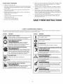
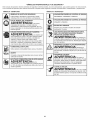
• SAFETY & iNTERNATiONAL SYMBOLS •
This operator's manual describes safety and international symbols and pictographs that may appear on this product. Read the operator's
manual for complete safety, assembly, operating and maintenance and repair information.
SYMBOL MEANING
, SAFETY ALERT SYMBOL
_ !ndicates danger I Wain!ng or cauti0n: MaY be used in
i ;ira . conjunction with other symbols or pictographs.
o READ OPERATOR'S MANUAL
WARNING: Readtheoperator's
manual(s) and follow a!! warnings and safety
instructionsl Failure to do so Can reSult in Serious
. injuryto the operator and/or bystanders.
4tii " WEAR EYE AND HEAR'NG PROTECT'ON
oWsiseAccanRcaN!Ngi :!:OuW_ _;:iteS :rid
! n;i ev i Y n] Y cJ aing :
Wear eye protection meeting Cur[ent ANSI/ISEA
Z871! standa[ds and ear protection when operating
this unit. Use afull face shield when needed.
%, UNL EDFUEL
AlwaYs use Clean, fresh unleaded fue!:
_,_,# .
.OIL
_L.5/J
. Refer to operator S manual for the proper type of Oil.
• DO NOT USE E85 FUELIN THIS UNIT
WARNIN G::"! has been ploven tha;
c_Onmtaaignieng,g[:ate rnethanndlO:f_ _thhtnwOlrWilnlti_.ke!y
SYMBOL MEANING
...... _ , ON/OFF STOP CONTROL
| oN/START/RUN
' ON/OFFSTOP CONTROL
OFF or STOP
' PRIMER BULB
Push primer bulb, fully and slowly, 10 times.
,l® ", THROWN OBJECTS AND ROTATING CUTTER CAN
/7_ CAUSE SEVERE INJURY
"" "--_'/ Sm o a be
WARNING: all bjectscn
J
prope ed at h gh speed, caus ng njury. Keep away
. from the rotating rotor.
' KEEP BYSTANDERS AWAY
e_Wpe_ R N !eN rgF:elK:etP,a'abY5tafelt r(1'5m)
. from the operating area.
' HOT SURFACE
I
WARN ! NG. Donottouchahotmuff,er
,_}t_,,,,q,, or cylinder. You may get burned. These parts get
_1_'_' extremely hot from operation. When turned off they
remain hot for a short time.
._' SHARP BLADE
,,_r_,,,,,_• Sharp blade on trimmer
attachment shield. To prevent serious injury, do not
• touch the line cutting blade.

CRAFTSMANLiMiTED WARRANTY
FOR TWO YEARS from the date of sale, this product is warranted against defects in material or workmanship.
WITH PROOF OF SALE, a defective product will receive free repair or replacement at option of seller.
ADDITIONAL LIMITED WARRANTY ON TRIMMER SHAFTS
FOR THE THIRD THROUGH TENTH YEAR from the date of sale, the outer metal housing of the upper and lower trimmer shafts is warranted
against defects in material or workmanship.
WiTH PROOF OF SALE, a new housing will be supplied free of charge. You are responsible for the labor cost of installation. This additional
coverage does not apply to inner trimmer shaft components.
For warranty coverage details to obtain free repair or replacement, visit the web page: www.craftsman.com/warranty
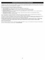
This warranty covers ONLY defects in material and workmanship. Warranty coverage does NOT include:
. Expendable items that can wear out from normal use within the warranty period, such as cutting line, spark plugs, or filters.
• Product damage resulting from user attempts at product modification or repair or caused by product accessories.
• Repairs necessary because of accident or failure to operate or maintain the product according to all supplied instructions.
• Preventive maintenance, or repairs necessary due to improper fuel mixture, contaminated or stale fuel.
This warranty is void if this product is ever used while providing commercial services or if rented to another person.
This warranty gives you specific legal rights, and you may also have other rights which vary from state to state.
Sears Brands Management Corporation, Hoffman Estates, IL 60179
To order parts or schedule service for this product, call 1-888-331-4569.
5

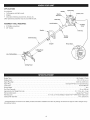
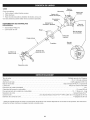
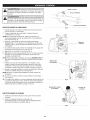
APPLiCATiONS
Asatrimmer:
• Cuttinggrassandlightweeds
Edging
Decorativetrimmingaroundtrees,fences,etc.
Otheroptionalaccessoriesmaybeusedwiththisunit.
Spark Plug
Muffler
Starter 1
Ro
Shaft Grip
Choke Lever
ASSEMBLY TOOLS REQUIRED:
= #2 Phillips screwdriver
• 3/8" Socket
Handle
On/Off Switch
Fuel Cap
Shaft Housing
Throttle
Control
Coupler Primer Bulb
Line Cutting Blad_
Cutting Head
Shield
Cutting Head
Engine Type ........................................................................................ Air-Cooled, 2-Cycle
Displacement ....................................................................................... 25 cc (1.52 cu. in.)
Spark Plug Gap .................................................................................... 0.025 in. (0.635 mm)
Spark Plug .......................................................................... Champion® RDJ7J or equivalent plug
Lubrication ........................................................................................... Fuel/Oil Mixture
Fuel/Oil Ratio .................................................................................................. 40:1
Fuel Tank Capacity ...................................................................................... 10 oz. (296 ml)
Approximate Unit Weight (No fuel) .................................................................... 10 - 11 Ibs. (4.5 - 5 kg)
Trimmer Mechanism ................................................................................. Hassle FreeTM Head
Trimming Line ................................................ 0.110 in. (2.79 mm) Medium Hassle FreeTM XTRA QUIET Spiral Line
Cutting Path Diameter .................................................................................. 14 in. (35.56 cm)
* All specifications are based on the latest product information available at the time of printing. We reserve the right to make changes at any
time without notice.

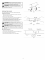
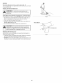
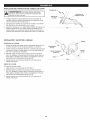
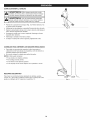
iNSTALLiNG THE CUTTING HEAD SHIELD
_ WARNING: To prevent serious personal injury, never ]
operate the unit without the cutting head shield in place.
1. Place the cutting head shield onto the mount bracket. Align the
holes in the cutting head shield with the holes in the mount
bracket. (Fig. 1)
Screw the 2 screws through the mount bracket and into the
cutting head shield until finger tight.
Using a #2 Phillips screwdriver, tighten the screws until the
cutting head shield is firmly in place. Tighten the screws equally.
The gap between the mount bracket and the cutting head shield
should be the same on each side.
2,
3.
Screws (2}
Mount Bracket " hield
Fig. 1
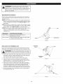
iNSTALLiNG AND ADJUSTING THE HANDLE
installing the Handle
1. Push the handle down onto the shaft housing (Fig. 2). The bolt
hole in the handle should be to the right.
2. Insert the bolt into the bolt hole and push it through (Fig. 2).
Tighten the bolt with a 3/8" socket, but do not tighten the bolt
completely.
3. While holding the unit in the operating position (Fig. 10), move
the handle to the location that provides the best grip. Place it a
minimum of 6 inches (15.24 cm) from the end of the shaft grip
(Fig. 2).
4. Tighten the bolt with a 3/8" socket until the handle is secure.
Adjusting the Handle
If the handle requires adjustment:
1. Loosen the bolt with a 3/8" socket (Fig. 2).
2. While holding the unit in the operating position (Fig. 10), move
the handle to the location that provides the best grip. Place it a
minimum of 6 inches (15.24 cm) from the end of the shaft grip
(Fig. 2).
3. Tighten the bolt with a 3/8" socket until the handle is secure.
Shaft Grip
Minimum 6 in.
(15.24cm}
Bolt J
Fig. 2
Handle
Shaft
Housing

WARNING: Before using any attachment, read and i
understand the manual that came with the attachment.
IFollow all safety information contained within.
WARNING: To avoid serious personal injury and i
damage to the unit, shut the unit off before removing or
I
installing an attachment.
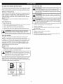
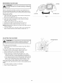
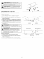
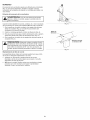
OPERATING THE COUPLER
The coupler enables the use of various optional attachments.
Installing the Attachment
1. Remove the cap from the attachment. If present, remove the
gray spacer from the coupler.
2. Set the unit on a flat, level surface.
3. Turn the knob counterclockwise to loosen the coupler (Fig. 3).
4. Align the release button with the guide recess (Fig. 5).
5. Push the attachment straight into the coupler (Fig. 4) until the
release button snaps firmly into the primary hole (Fig. 5).
6. Turn the knob clockwise to tighten the coupler (Fig. 3).
CAUTION: Before operating the unit, make sure the
release button is fully snapped into the primary hole and the
knob is securely tightened.
CAUTION: Unless specified otherwise, the release
button should be snapped into the primary hole only. Using
the wrong hole could lead to personal injury or damage to
the unit.
Removing the Attachment
1. Set the unit on a flat, level surface.
2. Turn the knob counterclockwise to loosen the coupler (Fig. 3).
3. Press and hold the release button (Fig. 5).
4. Pull the attachment straight out of the coupler (Fig. 4).
Tighten
Coupler
Primary Hole
Fig. 3
Fig. 4
Loosen
Knob
Attachment
Release Button
Guide Recess
Fig. 5

OiL AND FUEL MiXiNG iNSTRUCTiONS
FUELING THE UNiT
The use of old and/or improperly mixed fuel is the most common cause
of performance problems. Use only fresh, clean unleaded gasoline.
Follow the instructions carefully for the proper gasoline/oil mixture.
Definition of Blended Fuels
Today's fuels are often a blend of gasoline and oxygenates such as
ethanol, methanol or MTBE (ether). Alcohol-blended fuel absorbs
water. As little as 1% water in the fuel can make fuel and oil
separate, forming acids when stored. ALWAYS use fresh fuel (less
than 30 days old).
NOTE: Dispose of old fuel according to federal, state and local
regulations.
Using Blended Fuels
If using a blended fuel:
• Always use the fresh fuel mix explained in your operator's manual
Use the fuel additive STA-BIL® or an equivalent
Always agitate the fuel mix before fueling the unit
Drain the tank and run the engine dry before storing the unit
_WARNING: DO NOT USE E85 FUEL iN THiS UNIT. it |
g
has been proven that fuel containing greater than 10%
]
ethanol will likely damage this engine and void the warranty.
Using Fuel Additives
The bottle of 2-cycle oil provided with this unit contains a fuel
additive to help inhibit corrosion and minimize gum deposits.
Always use the brand of 2-cycle oil that came with this unit. If this is
unavailable, use a 2-cycle oil designed for air-cooled engines and
mix it with a fuel additive, such as STA-BIL Fuel Stabilizer or an
equivalent. Add 0.8 oz. (23 ml) of fuel additive per gallon of fuel,
according to the instructions on the container. NEVER add fuel
additives directly to the unit's fuel tank.
WARNING: Gasoline is extremely flammable, ignited
vapors may explode. Always stop the engine and allow it
to cool before filling the fuel tank. Do not smoke while
filling the tank. Keep sparks and open flames at a distance
from the area.
WARNING: Remove the fuel cap slowly to avoid injury
from fuel spray. Never operate the unit without the fuel cap
securely in place.
WARNING: Add fuel in a clean, well ventilated outdoor
area. Wipe up any spilled fuel immediately. Avoid creating
a source of ignition for spilled fuel. Do not start the engine
until fuel vapors dissipate.
1. Position the unit with the fuel cap facing up.
2. Remove the fuel cap.
3. Place the fuel container spout into the fill hole on the fuel tank
and fill the tank.
NOTE: Do not overfill the tank.
4. Wipe up any fuel that may have spilled.
5. Reinstall the fuel cap.
6. Move the unit at least 30 ft. (9.1 m) from the fuel container and
the fueling site before starting the engine.
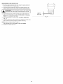
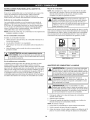
Mixing the Fuel
NOTE: This unit comes with a 3.2 oz. (95 ml) bottle of 2-cycle oil. To
obtain the correct fuel mixture described below, pour the entire
bottle into one gallon of unleaded gasoline.
CAUTION: For proper engine operation and maximum
reliability, pay strict attention to the gasoline and oil mixing
instructions on the 2-cycle oil bottle. Using improperly
mixed fuel can severely damage the engine.
Thoroughly mix the proper ratio of unleaded gasoline with 2-cycle
engine oil. Do not mix them directly in the unit's fuel tank. Use a
separate fuel can. Use a 40:1 gasoline/oil ratio. See the table below
for specific gasoline and oil mixing ratios.
Unleaded gasoline
1 gallon U.S.
(3.8 liters}
1 liter
2=cycle oil
3.2 fL oz.
(95ml}
25 ml
MIXING RATIO =40:1
9

I_ IWARNING: Operate this unit only in a well-ventilated
!
outdoor area. Carbon monoxide exhaust fumes can be
lethal in a confined area.
[_J WARNING: Avoid accidentally starting the unit. To avoid
serious injury, the operator and the unit must be in a stable
1
position when pulling the starter rope (Fig. 9).
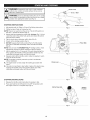
STARTING iNSTRUCTiONS
1. Mix gasoline with oil. Refer to Oil and Fuel Mixing Instructions.
2. Fill the fuel tank. Refer to Fueling the Unit.
NOTE: There is no need to turn the unit on. The On/Off switch is in
the ON (I) position at all times (Fig. 6).
3. Slowly press and release the primer bulb 10 times (Fig. 7). If fuel
cannot be seen in the primer bulb, press and release the primer
bulb until fuel is visible.
4. Flip the choke lever clockwise until it clicks (Fig. 8).
5. Crouch in the starting position (Fig. 9).
6. DO NOT squeeze the throttle control (Fig. 6). Pull the starter
rope with a controlled and steady motion until the unit starts
(Fig. 9).
NOTE: This unit uses the INCREDI-PULL TM starting system, which
significantly reduces the effort required to start the engine.
7. Idle the engine for 5 to 10 seconds. If the unit stops during this
time, squeeze the throttle control and pull the starter rope in a
controlled and steady motion until the unit starts.
8. Squeeze and hold the throttle control. Allow the engine to warm
up for 30 to 60 seconds.
NOTE: The engine is properly warmed up when it accelerates
without hesitation.
IF... the engine does not start, begin the starting procedure with
step 3.
IF... the unit is hot and fails to start within 3 pulls of the starter rope,
squeeze the throttle control and pull the starter rope with a
controlled and steady motion until the unit starts.
Choke Lever
Fig. 6
Fig. 7
Throttle Control
Primer Bulb
STOPPING iNSTRUCTiONS
1. Release the throttle control and allow the engine to idle.
2. Press and hold the On/Off switch in the OFF (O) position until
the engine comes to a complete stop (Fig. 6).
Fig. 8
Starter Rope Grip
(
Fig. 9
Starting
Position
10

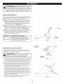
HOLDING THE UNiT
WARNING: Always wear eye, hearing, hand, foot and i
body protection to reduce the risk of injury when operating
I
this unit.
WARNING: To prevent serious personal injury, avoid arm I
contact with the engine while operating the unit. The
!
engine may be extremely hot.
• Stand in the operating position (Fig. 10). Stand up straight. Do
not bend over.
Keep feet apart and firmly planted.
Hold the shaft grip with the right hand. Keep the right arm
slightly bent.
Hold the handle with the left hand. Keep the left arm straight.
Hold the unit at waist level.
Position the cutting head a few inches above the ground.
o
o
o
o
o
Fig. lo
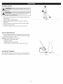
TiPS FOR BEST RESULTS
= To direct clippings away from the operator, tilt the cutting head
slightly down to the left; cut from right to left whenever possible.
Do not trim wet grass or weeds.
NOTE: Some line breakage will occur from:
Entanglement with foreign matter
Normal line fatigue
Attempting to cut thick vegetation
Forcing the line into objects such as walls or fence posts
DECORATIVE TRiMMiNG
When trimming around trees, posts, fences, etc., rotate the whole
unit so that the cutting head is at a 30 ° angle to the ground (Fig. 11).
Fig. 11
11

EDGING
The trimmer attachment can be used for edging (Fig. 12).
Alternatively, bladed lawn edger attachments can also be purchased
for use with this unit.
Rotating the Trimmer Attachment
_ WARNING: To avoid serious personal injury and I
I
damage to the unit, shut the unit off before rotating the
1
attachment.
When edging around sidewalks, flowerbeds, etc., rotate the trimmer
attachment 90° inside the coupler. DO NOT rotate the entire unit 90°.
1. Turn the knob counterclockwise to loosen the coupler (Fig. 3).
Refer to Operating the Coupler in the Assembly section.
2. Press and hold the release button (Fig. 5).
3. Rotate the attachment until the release button snaps firmly into
the 90° edging hole (Fig. 13).
4. Turn the knob clockwise to tighten the coupler (Fig. 3).
CAUTION: Only snap the release button into the 90°
edging hole when edging with the trimmer attachment.
Using the 90 ° edging hole with other attachments could
lead to personal injury or damage to the unit.
Maintaining the Trimming Line
Hard surfaces, such as sidewalks, can cause the trimming line to
wear down quickly or break.
• Frequently check the trimming line length. Replace the trimming
line as needed. Refer to Replacing the Trimming Line.
DO NOT force the unit. Make shallow cuts in as many passes as are
necessary to achieve the desired depth. Cut at a slow, even pace.
Fig. 12
Release
Hole
Fig. 13
12

WARNING: To prevent serious injury, never perform
maintenance or repairs while the unit is running. Always
allow the unit to cool before servicing or repairing the unit.
Disconnect the spark plug wire to prevent the unit from
starting accidentally.
MAINTENANCE SCHEDULE
Perform these required maintenance procedures at the frequency
stated in the table. These procedures should also be a part of any
seasonal tune-up.
NOTE: Some maintenance procedures may require special tools or
skills. If unsure about these procedures, take the unit to a Sears
or other qualified service dealer. Call 1-888-331-4569 for more
information.
NOTE: Maintenance, replacement, or repair of the emission control
devices and system may be performed by a Sears or other qualified
service dealer. Call 1-888-331-4569 for more information.
NOTE: Please read the California/EPA statement that came with the
unit for a complete listing of terms and coverage for the
emissions control devices, such as the spark arrestor, muffler,
carburetor, etc.
FREQUENCY MAINTENANCE REQUIRED
Every 10 hours Clean and re-oil the air filter. Refer to
Maintaining the Air Filter.
Every 25 hours Check the spark plug condition and gap. Refer
to Maintaining the Spark Plug.
Holes
Fig. 14
Line
Cutting Head
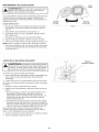
REPLACING THE TRiMMiNG LiNE
Only use the trimming line described in the Specifications section.
Other types of trimming line may cause the unit to overheat or fail.
I_ IWARNING: Never use metal-reinforced line, wire, chain or |
!
rope. These can break off and become dangerous projectiles.
J
1. Remove the old line from the cutting head. Push one end of the
trimming line into the cutting head until a loop of line protrudes
from the head. Pull the loop to remove the line.
2. Use a clean cloth to clean the surface of the cutting head.
3. Insert the ends of the new trimming line into the holes in the
cutting head (Fig. 14). Push the line through the holes until both
ends protrude from the positioning tunnels (Fig. 15).
4. Pull the ends of the line until the line is tight against the cutting
head. Make sure the ends of the line are of equal length (Fig. 16).
If one end is longer than the other, push the longer end back
through the cutting head partway and pull the shorter end out. If
necessary, repeat this process until both ends are of equal length.
5. Press the exposed loop of trimming line until it is tight against
the cutting head (Fig. 16).
Positioning
Tunnel
Tunnel
Line
Fig. 15
Loop
Line
Fig. 16
13

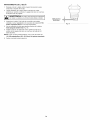
MAiNTAiNiNG THE AiR FILTER
_ WARNING: To avoid serious personal injury, always stop
the engine and allow it to cool before cleaning or maintaining
J
the unit.
Failure to maintain the air filter can result in poor performance or
can cause permanent damage to the engine. Engine failure due to
improper air filter maintenance is not covered by the product warranty.
Cleaning the Air Filter
1. Open the air filter cover: press in the lock tab and swing the air
filter cover to the right (Fig. 17).
2. Remove the air filter from inside the air filter cover (Fig. 17).
3. Wash the air filter in detergent and water. Rinse the air filter
thoroughly and allow it to dry.
4. Lightly coat the air filter with clean SAE 30 oil.
5. Squeeze the air filter to spread and remove excess oil.
6. Reinstall the air filter inside the air filter cover (Fig. 17).
NOTE: Operating the unit without the air filter and air filter cover will
VOID the warranty.
7. Close the air filter cover: swing the air filter cover to the left and
press it closed until the lock tab snaps into place (Fig. 17).
Air Filter
i!!!il "2, ',,
/
Lock Tab Air Filter Cover
Fig. 17
ADJUSTING THE iDLE SPEED
_ ARNING: The cutting head may spin during idle speed_
adjustments. Wear protective clothing and observe all
Jsafety instructions to prevent serious personal injury.
If the engine will not idle properly:
1. Drain the fuel tank and add fresh, properly-mixed fuel. Refer to
Oil and Fuel.
2. Clean the air filter. Refer to Maintaining the Air Filter.
If the engine still will not idle properly, adjust the idle speed:
1. Start the engine. Refer to Starting and Stopping.
2. Release the throttle control and let the engine idle.
• If the engine stops, increase the idle speed. Use a small
Phillips screwdriver to turn the idle speed screw clockwise,
1/8 of a turn at a time, until the engine idles smoothly (Fig. 18).
If the cutting head spins when the engine idles, reduce the idle
speed. Turn the idle speed screw counterclockwise, 1/8 of a
turn at a time, until the cutting head stops moving (Fig. 18).
If the engine still will not idle properly, and any of the following
conditions are true, take the unit to a Sears or other qualified service
dealer:
the engine hesitates or stalls on acceleration
there is a loss of engine power
idle Speed Screw
Fig. 18
14

MAiNTAiNiNG THE SPARK PLUG
1. Stop the engine and allow it to cool. Grasp the spark plug boot
firmly and pull it from the spark plug.
2. Clean around the spark plug. Remove the spark plug from the
cylinder head with a 5/8-inch socket, turning counterclockwise.
I _ib !WARNING: Do not sand blast, scrape or clean spark plug I
electrodes. Grit in the engine could damage the cylinder.
3. Inspect the spark plug. If the spark plug is cracked, fouled or
dirty, replace it with replacement part #753-06193, a Champion
RDJ7J or an equivalent spark plug.
4. Use a feeler gauge to set the air gap at 0.025 in. (0.635 ram}
(Fig. 19).
5. Install the spark plug in the cylinder head. Tighten the spark plug
with a 5/8-inch socket, turning it clockwise until snug.
NOTE: If using a torque wrench, torque to:
110=120 in.olb. (12.3=13.5 Nora). Do not over tighten.
6. Reattach the spark plug boot.
0.025 in.
(0.635 rnrn}
Fig. 19
15

CLEANING STORAGE
_ WARNING" To avoid serious personal injury, always stop
the engine and allow it to cool before cleaning or maintaining
J
the unit.
Use a small brush to clean the outside of the unit. Do not use strong
detergents. Household cleaners that contain aromatic oils such as
pine and lemon, and solvents such as kerosene, can damage
plastic. Wipe off any moisture with asoft cloth.
• Never store a fueled unit where fumes may reach an open flame
or spark.
Allow the engine to cool before storing.
Lock up the unit to prevent unauthorized use or damage.
Store the unit in a dry, well-ventilated area.
Store the unit out of the reach of children.
Short-term Storage (1-2 weeks)
1. Store the unit in a horizontal position. If this is not possible, store
the unit vertically with the engine at the top.
Long-term Storage
1. Remove the fuel cap, tip the unit and drain the fuel into an
approved container. Reinstall the fuel cap.
2. Start the engine and allow it to run until it stalls. This ensures
that all fuel has been drained from the carburetor.
3. Allow the engine to cool. Remove the spark plug and put 5
drops of any high-quality motor oil or 2-cycle oil into the
cylinder. Pull the starter rope slowly to distribute the oil. Reinstall
the spark plug.
4. Thoroughly clean the unit and inspect it for any loose or
damaged parts. Repair or replace damaged parts and tighten
loose screws, nuts or bolts.
Preparing the Unit for Use after Long-term Storage
1. Remove the spark plug and drain all of the oil from the cylinder.
NOTE: Do not use fuel that has been stored for more than 30 days.
Dispose of old fuel according to federal, state and local regulations.
16

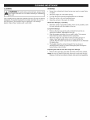
PROBLEM
The fuel tank is empty
The engine is flooded
The spark plug is fouled
SOLUTION
Fill the fuel tank with properly mixed fuel
iii [ [ """""""""""""""'"""""""""""""""""""""'"'
Squeeze the throttle control and pull the starter rope until the engine
starts
Replace the spark plug
The air filter is dirty
The idle speed is incorrect
The fuel is old (over 30 days) and/or improperly mixed
The air filter is dirty
The fuel is old (over 30 days) and/or improperly mixed
The spark plug is fouled
Clean or replace the air filter
Adjust the idle speed
Drain the fuel tank and add fresh, properly-mixed fuel
Clean or replace the air filter
Drain the fuel tank and add fresh, properly-mixed fuel
Replace the spark plug
° Find information and tools to help with home projects.
brought to you by Sears
17

Congratulations on making a smart purchase. Your new Craftsman@ product is designed and manufactured for years of dependable
operation. But like all products, it may require repair from time to time. That's when having a Repair Protection Agreement can save you
money and aggravation.
Here's what the Repair Protection Agreement* includes:
[] Expert service by our 10,000 professional repair specialists
[] Unlimited service and no charge for parts and labor on all covered repairs
[] Product replacement up to $1500 if your covered product can't be fixed
[] Discount of 25% from regular price of service and related installed parts not covered by the agreement; also, 25% off regular price of
preventive maintenance check
[] Fast help by phone - we call it Rapid Resolution - phone support from a Sears representative. Think of us as a "talking owner's manual."
Once you purchase the Repair Protection Agreement, a simple phone call is all that it takes for you to schedule service. You can call anytime
day or night, or schedule a service appointment online.
The Repair Protection Agreement is a risk-free purchase. If you cancel for any reason during the product warranty period, we will provide a
full refund. Or, a prorated refund anytime after the product warranty period expires. Purchase your Repair Protection Agreement today!
Some limitations and exclusions appJy. For prices and additional information in the U.S.A. call 1-800-827-6655.
*Coverage in Canada varies on some items. For full details call Sears Canada at 1-800-361-6665.
Sears installation Service
For Sears professional instaflation of home appliances, garage door openers, water heaters, and other major home items, in the U.S.A. or
Canada call 1-800-4-MY-HOME.
18

Manual del Operador
Motor de 2 tiernpos
RECORTADOR WEEDWACKER_ A GASOLINA
Modelo No. 316.711191
PRECAUCION: Antes de utilizar, este
producto lea este manual y siga todas
las reglas de seguridad e instrucciones
de operaci6n.
* SEGURIDAD
* ENSAMBLAJE
. OPERACION
* MANTENIMIENTO
Sears Brands Management Corporation, Hoffman Estates, iL 60179 U.S.A.
Visite nuestro sitio web: www.craftsman.com
769-10237 / 00 09/14
Page is loading ...
Page is loading ...
Page is loading ...
Page is loading ...
Page is loading ...
Page is loading ...
Page is loading ...
Page is loading ...
Page is loading ...
Page is loading ...
Page is loading ...
Page is loading ...
Page is loading ...
Page is loading ...
Page is loading ...
Page is loading ...
Page is loading ...
Page is loading ...
Page is loading ...
Page is loading ...

Product questions or problems?
Customer Care ot Line
Get answers to questions, troubleshoot problems,
order parts, or schedule repair service.
Para respuestas a preguntas o problemas, y ordenar
piezas o pedir servicio para la reparaci6n de su equipo.
To help us help you, register your product at www.craftsman.com/registration
Para poderte ayudar mejor, registra tu producto en www.craftsman.com/registration
Join the Craftsman Club todayZ
CRRFT :MRN
www.craftsman.com/signup
Receive exclusive member benefits including special pricing and offers,
project sharing, expert advice, and SHOP YOUR WAY REWARDS!
Como miembro exclusivo, recibe diversos beneficios como ofertas, precios especiales, proyectos
nuevos, consejos de expertos y nuestro programa de puntos SHOP YOUR WAY REWARDS!
® Registered Trademark /TM Trademark of KCD IP, LLC in the United States, or Sears Brands, LLC in other countries
® Marca Registrada/TM Marca de FAbrica de KCD IP, LLC en Estados Unidos, o Sears Brands, LLC in otros paises
-
 1
1
-
 2
2
-
 3
3
-
 4
4
-
 5
5
-
 6
6
-
 7
7
-
 8
8
-
 9
9
-
 10
10
-
 11
11
-
 12
12
-
 13
13
-
 14
14
-
 15
15
-
 16
16
-
 17
17
-
 18
18
-
 19
19
-
 20
20
-
 21
21
-
 22
22
-
 23
23
-
 24
24
-
 25
25
-
 26
26
-
 27
27
-
 28
28
-
 29
29
-
 30
30
-
 31
31
-
 32
32
-
 33
33
-
 34
34
-
 35
35
-
 36
36
-
 37
37
-
 38
38
-
 39
39
-
 40
40


Craftsman 316711191 Owner's manual
- Category
- Grass trimmers
- Type
- Owner's manual
- This manual is also suitable for
Ask a question and I''ll find the answer in the document
Finding information in a document is now easier with AI
in other languages
Related papers
-
Craftsman 41BDZ46C799 Owner's manual
-
Craftsman Weedwacker 316.794490 User manual
-
-
-
-
-
-
-
-