Simplicity 040490-00 Installation guide
- Category
- Power generators
- Type
- Installation guide

Not for
Reproduction
Generator
Home Generator Systems
Installation Instructions
Series 14000
Copyright © Briggs & Stratton Corporation, Milwaukee, WI, USA.
All rights reserved.
80010856 Revision A

Not for
Reproduction
This generator is declared compliant to
IP23W requirements per IEC 60529
Thank you for purchasing this quality-built Briggs & Stratton® home generator. We are pleased that you’ve placed your
confidence in the Briggs & Stratton brand. When operated and maintained according to the instructions in the operator’s
manual, your home generator will provide many years of dependable service.
This manual contains safety information to make you aware of the hazards and risks associated with residential generator
systems and how to avoid them. This generator system is designed and intended only for use as an optional home standby
system that provides an alternate source of electric power and to serve loads such as heating, refrigeration systems, and
communication systems that, when stopped during any power outage, could cause discomfort or inconvenience. Save
these original instructions for future reference.
This generator system requires professional installation before use. The installer should follow the instructions
completely.
Where to Find Us
You never have to look far to find support and service for your generator. Consult your Yellow Pages. There are many
Briggs & Stratton authorized service dealers worldwide who provide quality service. You can also contact Briggs &
Stratton Customer Service by phone at 800 732-2989 between 8:00 AM and 5:00 PM CT., or click on Find a Dealer at
BRIGGSandSTRATTON.COM, which provides a list of authorized dealers.
These original instructions contain safety information to make you aware of the hazards and risks associated with
residential generator systems and how to avoid them. This product is intended for use as an optional system which provides
an alternate source of electric power and to serve loads such as heating, refrigeration systems, and communication systems
that, when stopped during any power outage, could cause discomfort or inconvenience.
IMPORTANT - READ INSTRUCTIONS IN FULL.
IMPORTANT - SAVE THIS MANUAL FOR FUTURE REFERENCE.
For Future Reference
Please fill out the information below and keep with your receipt to assist in unit identification for future purchase issues.
Date of Purchase
Generator
Model Number
Model Revision
Serial Number
Engine
Model Number
Serial Number

Not for
Reproduction
3
Table of Contents
SAFETY INSTRUCTIONS ................................................................................. 4
Safety Signs .................................................................................................................. 4
Safety Alerts .................................................................................................................. 4
SAFETY RULES AND INFORMATION ............................................................. 8
Safety Rules .................................................................................................................. 8
INSTALLATION ................................................................................................. 9
Shipment Contents ....................................................................................................... 9
Unpacking Precautions ................................................................................................. 9
Delivery Inspection ........................................................................................................ 9
Skilled Person .............................................................................................................. 9
Equipment Description ................................................................................................ 10
Skilled Persons Responsibilities ................................................................................. 10
Cold Start Kit ............................................................................................................... 10
Installation Checklist ................................................................................................... 11
Generator Placement .................................................................................................. 13
Carbon Monoxide Hazard Safety Placement Requirements ....................................... 14
Fire Hazard Safety Placement Requirements ............................................................. 17
Electrical and Fuel Inlet Locations .............................................................................. 18
Lifting the Generator ................................................................................................... 19
Concrete Anchoring .................................................................................................... 19
Roof Access ................................................................................................................ 20
Gaseous Fuel System ................................................................................................. 21
Before Installing Fuel System...................................................................................... 21
Fuel Consumption ....................................................................................................... 22
LP Vapor (Propane) .................................................................................................... 22
Natural Gas ................................................................................................................. 22
Fuel Pressure .............................................................................................................. 22
Power Loss ................................................................................................................. 22
Fuel Pipe Sizing .......................................................................................................... 22
Fuel Conversion .......................................................................................................... 22
System Connectors ..................................................................................................... 23
Grounding the Generator ............................................................................................ 24
Generator Power Connection ...................................................................................... 24
Utility Circuit Connection ............................................................................................. 24
Communication Connections ...................................................................................... 24
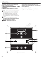
Generator AC Connection System ............................................................................. 25
System Control Panel ................................................................................................. 26
Menu .......................................................................................................................... 27
General Set Up Screen ............................................................................................... 28
Control Panel Prompts ................................................................................................ 29
Automatic Mode .......................................................................................................... 29
General System Parameters ....................................................................................... 29
Advanced Settings Screen .......................................................................................... 30
Service Code Detection System ................................................................................. 31
Final Installation Considerations ................................................................................. 31
Engine Oil ................................................................................................................... 31
Battery ......................................................................................................................... 31
Initial Start-Up (No Load) ............................................................................................ 32
Electronic Governor System ....................................................................................... 33
Electronic Governing Check ....................................................................................... 33
OPERATION .................................................................................................... 34
Automatic Operation Sequence .................................................................................. 34
Utility Voltage Dropout Sensor .................................................................................... 34
Engine Cool-Down Timer ............................................................................................ 34
Setting Local Date and Time ....................................................................................... 34
Setting Exercise Timer ................................................................................................ 34
EQUIPMENT SPECIFICATIONS ..................................................................... 35
SCHEMATIC DIAGRAM .................................................................................. 36

Not for
Reproduction
4
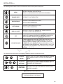
Safety Signs
Safety Alerts
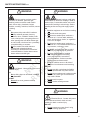
The safety alert symbol indicates a potential personal injury hazard. A signal word, such as DANGER, WARNING, or
CAUTION, is used with the alert symbol to designate a degree or level of hazard seriousness. A safety symbol may be used
to represent the type of hazard.
DANGER
Danger indicates a hazard with a high level of risk which, if not avoided, will result in death or serious injury.
WARNING
Warning indicates a hazard with a medium level of risk which, if not avoided, could result in death or serious injury.
CAUTION
Caution indicates a hazard with a low level of risk which, if not avoided, could result in minor or moderate injury.
NOTICE
The manufacturer cannot possibly anticipate every possible circumstance that might involve a hazard. The warnings in this
manual, and the tags/decals axed to the generator are, therefore, not all-inclusive. If you use a procedure, work method or
operating technique that the manufacturer does not specically recommend, you must satisfy yourself that it is safe for you
and others. You must also make sure that the procedure, work method or operating technique that you choose does not render
the generator unsafe.
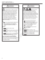
SAFETY INSTRUCTIONS
Flammable material
Toxic fumes
Lift hazard
Refer to instruction
manual/booklet
Corrosive substanceAutomatic start-up
Hot surfaceRotating parts
Electrical shockExplosive material

Not for
Reproduction
5
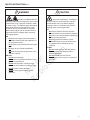
SAFETY INSTRUCTIONS cont.
WARNING
Electrical Shock - Contact with power
lines could cause electric shock or burns,
resulting in death or serious injury.
DO NOT
• Do not contact any power lines if using
lifting or hoisting equipment.
WARNING
Exhaust heat/gas could ignite
combustibles or structures resulting in death or
serious injury. Contact with muffler area could
cause burns resulting in serious injury. Before
installing and/or servicing fuel supply system:
DO
• Do allow equipment to cool before touching.
• Do avoid hot exhaust gases.
• Do locate the weatherproof enclosure a
minimum of 1.5 m from walls, windows,
doors, wall openings, shrubs, or vegetation
over 0.3 m in height.
• Do locate the weatherproof enclosure a
minimum of 1.5 m overhead clearance from
any structure, overhang or trees.
• Do ONLY use flexible fuel line provided.
Connect provided fuel line to generator.
• Do have smoke detectors installed
and maintained indoors according
to the manufacturer’s instructions/
recommendations. Carbon monoxide
detectors cannot detect smoke.
• Do allow sufficient room on all sides of
generator for maintenance and servicing.
DO NOT
• Do not use with or substitute the flexible
fuel line provided with any other fuel line.
• Do not place weatherproof enclosure under
a deck or any other type of structure that
may confine airflow.
• Do not touch hot parts.
• Do not smoke around generator.
WARNING
Running engine produces carbon
monoxide, an odorless, poisonous gas.
Breathing carbon monoxide could result in
death, serious injury, headache, fatigue,
dizziness, vomiting, confusion, seizures, nausea
or fainting.
DO
• Do operate this product ONLY outdoors.
• Do keep exhaust gas away from any
windows, doors, ventilation intakes, soffit
vents, crawl spaces, open garage doors or
other openings that can allow exhaust gas
to enter inside or be drawn into a potentially
occupied building or structure.
• Do have carbon monoxide detectors
installed and maintained indoors
according to manufacturer’s instructions/
recommendations. Smoke alarms cannot
detect carbon monoxide gas.
WARNING
Lift Hazard - Heavy object could result
in serious injury.
DO
• Do use lifting pipes as described in Lifting
the Generator.
DO NOT
• Do not lift or move generator without
assistance.

Not for
Reproduction
6
SAFETY INSTRUCTIONS cont.
WARNING
Electrical Shock - Failure to properly
ground generator could result in electrocution.
Failure to isolate generator from utility power
could result in death or serious injury to utility
workers due to backfeed of electrical energy.
If you must work around a unit while it is
operating, stand on an insulated dry surface
to reduce risk of shock hazard. Despite
the safe design of the generator, operating
this equipment imprudently, neglecting its
maintenance or being careless could result in
death or serious injury.
DO
• Do have the electrical system meet national
rules and regulations of the respective
country when generator is installed. This
includes the Residual Current Device
(RCD).
DO NOT
• Do not touch bare wires or bare
receptacles.
• Do not use generator with electrical cords
which are worn, frayed, bare or otherwise
damaged.
• Do not handle generator or electrical cords
while standing in water, while barefoot, or
while hands or feet are wet.
In case of an accident caused by electrical
shock, immediately shut down the source of
electrical power and contact the local authorities
or emergency response units. Avoid direct
contact with the victim.
WARNING
Storage batteries
give off explosive hydrogen gas during
recharging. The slightest spark will ignite
hydrogen and cause explosion, resulting in
death or serious injury. Battery electrolyte fluid
contains acid and is extremely caustic. Contact
with battery contents could cause severe
chemical burns. A battery presents a risk of
electrical shock and high short circuit current.
Before installing and/or servicing battery:
DO
• Do use tools with insulated handles.
• Do wear PPE (Personal Protective
Equipment) of protective goggles, rubber
apron, rubber boots and rubber gloves.
• Do remove all metal objects, such as
jewelry, watches or rings.
• Do recycle battery through your local
recycling company.
DO NOT
• Do not dispose of battery in a fire.
• Do not allow an open flame, spark, heat, or
lit cigarette in vicinity during and for several
minutes after servicing a battery.
• Do not open or mutilate battery.

Not for
Reproduction
7
SAFETY INSTRUCTIONS cont.
WARNING
Propane and Natural Gas are
extremely flammable and explosive, which could
cause burns, fire or explosion resulting in death
or serious injury. The slightest spark could ignite
these fuels and cause an explosion. LP gas
is heavier than air and will settle in low areas.
Natural gas is lighter than air and will collect in
high areas. Before installing and/or servicing
fuel supply system:
DO
• Do install fuel supply system according to
applicable national rules and regulations of
the respective country.
• Do properly purge and leak test fuel system
lines.
• Do wipe up any oil spills immediately.
• Do keep the area near the generator clean
and free of debris.
DO NOT
• Do not permit leakage.
• Do not leave combustible materials in the
generator compartment.
• Do not operate engine if smell of fuel is
present or other explosive conditions exist.
• Do not smoke around generator.
• Do not have any open flames around
generator.
CAUTION
Auto start of Machinery - Installing the
15 Amp (15A) fuse could cause the engine to
crank and start at any time without warning
resulting in minor to moderate injury. Before
installing and/or servicing generator:
DO
• Do observe that the 15A fuse has been
removed from the control panel for shipping.
• Do remove the 15A fuse before maintaining
and/or servicing generator.
• Do always press and hold the control
board OFF button to prevent sudden start
of generator when maintaining and/or
servicing.
DO NOT
• Do not install 15A fuse until all plumbing
and wiring has been completed when
installing generator.
• Do not reinstall 15A fuse until all
maintenance and/or service is complete on
generator.

Not for
Reproduction
8
SAFETY RULES AND INFORMATION
Safety Rules
NOTICE
Improper treatment of generator could
damage it, shorten its life, and void warranty
1. Read, understand, and follow all instructions in the
manual and on the generator before starting equipment.
2. Use generator only for intended uses.
3. If you are not sure that the task you are about to perform
can be safely done with the equipment you have
chosen, ask a skilled person at your local authorized
dealer.
4. Install generator only on level surfaces.
5. Adequate, unobstructed flow of cooling and ventilating
air is critical to correct generator operation.
6. The access panels/doors must be installed whenever
the generator is running.
7. Remain alert at all times while working on this
equipment. Do not work on the equipment when you are
physically or mentally fatigued.
8. If connected devices overheat, turn them off and
disconnect them from generator.
9. Do not modify generator in any way.
10. Do not expose generator to excessive moisture, dust,
dirt, or corrosive vapors.
11. Do not start engine with air cleaner removed or air
cleaner cover removed.
12. Do not insert any objects through cooling slots.
13. Do not use the generator or any of its parts as a step.
Stepping on the generator could break parts. This may
result in dangerous operating conditions from leaking
exhaust gases, fuel leakage, oil leakage, etc.
14. Do not allow unqualified persons or children to operate
or service generator.
15. After the system is installed, the generator may crank
and start at any time, without warning. To prevent
possible injury while working on equipment, depress
the OFF button on the generator control panel. Then
remove the 15 A fuse from the generator control panel.

Not for
Reproduction
9
Shipment Contents
The generator is supplied with:
• Oil (5W30 Synthetic)
• Flexible steel fuel line
• Installation Instructions
• User’s Instructions
• Spare access roof keys
• Spare 15 A ATO-type fuse
• Tamper proof plug
Not Included:
• Carbon monoxide detector(s)
• Smoke detector(s)
• Starting battery
• Connecting wire and conduit
• Fuel supply valves/plumbing
• Two 1.5 m lengths of 25 mm (Outer Diameter) and
minimum 2.5 mm wall thickness steel pipe
• Hole punches for 1.6 mm steel
• Cyanoacrylate glue
• Concrete slab (if needed)
• Pipe thread sealant
Unpacking Precautions
The generator is shipped ready for installation. Avoid
damage from dropping, bumping, collision, etc. Store and
unpack carton with proper side up, as noted on the shipping
carton.
Delivery Inspection
After removing the carton, carefully inspect the
generator for any damage that may have occurred during
shipment.
If loss or damage is noted at time of delivery, have the
person(s) making the delivery note all damage on the freight
bill and ax his signature under the consignor’s memo of
loss or damage. If loss or damage is noted after delivery,
separate the damaged materials and contact the carrier
for claim procedures. Parts damaged in shipping are not
warranted.
This manual is specically targeted for the skilled person.
Skilled Person
Individual with relevant technical education, training and/
or experience enabling him or her to perceive risks and to
avoid hazards occurring during use of a product.
INSTALLATION
CAUTION
Auto start of Machinery - Installing the
15 Amp (15A) fuse could cause the engine to
crank and start at any time without warning
resulting in minor to moderate injury. Before
installing and/or servicing generator:
DO
• Do observe that the 15A fuse has been
removed from the control panel for shipping.
• Do remove the 15A fuse before maintaining
and/or servicing generator.
• Do always press and hold the control
board OFF button to prevent sudden start
of generator when maintaining and/or
servicing.
DO NOT
• Do not install 15A fuse until all plumbing
and wiring has been completed when
installing generator.
• Do not reinstall 15A fuse until all
maintenance and/or service is complete on
generator.

Not for
Reproduction
10
Equipment Description
This product is intended for use as an optional system
which provides an alternate source of electric power and
to serve loads such as heating, refrigeration systems, and
communication systems that, when stopped during any
power outage, could cause discomfort or inconvenience.
Every effort has been made to ensure that information in
this manual is accurate and current. However, we reserve
the right to change, alter, or otherwise improve the product
and this document at any time without prior notice.
Skilled Persons Responsibilities
• Read and follow the instructions given in the installation
instructions.
• The generator warranty is VOID unless the system is
installed by skilled persons.
• Carbon monoxide detector(s) MUST be installed and
maintained indoors according to the manufacturer’s
instructions/recommendations. Smoke alarms cannot
detect carbon monoxide gas.
• Smoke detector(s) MUST be installed and maintained
indoors according to the manufacturer’s instructions/
recommendations. Carbon monoxide alarms cannot
detect smoke.
• Any deviations from manufacturer’s recommendations/
instructions will void warranty.
• Read and observe the safety rules.
• Installation must strictly comply with all applicable
national rules and regulations of the respective country.
• Allow sufficient room on all sides of the generator for
maintenance and servicing.
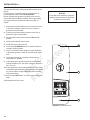
Cold Start Kit
It is HIGHLY RECOMMENDED to install a Model 6231 Cold
Start Kit (includes two oil warmers and battery warmer) on
the generator for operation below -1°C.
For cold weather areas (below -18°C) it is also
recommended to use a BCI, Group Size 75F, wet lead-acid
battery with a minimum rating of 630 CCA.
NOTICE
Only skilled persons should attempt generator
installations. Installations must strictly comply with
all applicable national rules and regulations of the
respective country.
INSTALLATION cont.
Figure 1 Cold Start Kit
-1°C

Not for
Reproduction
11
Installation Checklist
Carbon Monoxide (CO) Detector
Carbon Monoxide (CO) detector(s) installed and in
working order.
Smoke detector(s) installed and in working order.
Placement
Required permits have been obtained.
Generator is placed in an area free from Carbon
Monoxide (CO) buildup. See Carbon Monoxide
Hazard Safety Placement Requirements.
Generator is placed in an area free from potential water
damage.
Generator is placed in an area free from utility and other
home systems.
Generator is placed in a debris free zone.
Generator is placed on flat ground with provisions for
water drainage.
Fuel
Generator is connected to fuel source with flexible fuel
line, has no fuel leaks and conforms to national rules
and regulations of the respective country.
See Gaseous Fuel System.
Proper fuel pressure has been measured with all gas
appliances operating. See Gaseous Fuel System.
Fuel system has been configured for the proper fuel
supply: Natural gas (NG) or liquefied petroleum (LP).
See Fuel Conversion.
Fuel type: (circle one) NG LP
Fuel pipe size used: (circle one) 19mm 25mm 32mm
38mm
Fuel pressure at fuel inlet port with generator on and at
full load and all gas appliances turned on and operating
____________________.
Electrical
Generator is connected to Automatic Transfer Switch.
See Generator AC Connection System.
Generator is grounded. See Grounding the
Generator.
Generator is connected to the transfer switch with the
specified wiring. See Utility Circuit Connection and
Communication Connections.
Generator is connected to the transfer switch with the
specified wiring. #0.82 mm² twisted pair wiring from the
generator control panel to the transfer switch is installed
in a separate conduit from high voltage wires unless
the insulation rating on all wiring is rated for 600V. See
Communication Connections.
Dipswitches in most transfer switches must be set
to correspond to the wattage of the generator. See
Transfer Switch Operator/Installation Manual.
Operation
Cold weather kit is installed in temperatures below -1°C.
See Cold Weather Kit.
Correct battery type is installed and fully charged. See
Final Installation Considerations.
Generator engine oil level is at full mark. See Final
Installation Considerations.
All circuit breakers are in the ON position (Generator and
Transfer Switch).
Utility was shut off to test the operation of generator
and transfer switch. Note any service codes and make
corrections as required.
AC Voltage Output___________________________.
Frequency Output___________________________.
Owner Information
Name: _______________________________________
Address: _____________________________________
Phone/e-mail:__________________________________
Generator Information
Generator Model: _______________________________
Generator Serial Number: ________________________
Installing Contractor Information
Name: _______________________________________
Address: _____________________________________
Phone/FAX: ___________________________________
Electrician: ___________________________________
Signature: ____________________________________
Plumber: _____________________________________
Signature: ____________________________________
Inspector Information
Name: _______________________________________
Address: _____________________________________
_____________________________________________
Title: _________________________________________
Inspection Date: ________________________________
This generator has been installed per the manufacturer’s
instructions:
Installing Contractor Signature: _________________________
Date: _____________________________________________
Proper installation of the generator requires the completion of the following tasks. Fill out the information below and give to
the user.

Not for
Reproduction
12
This page intentionally left blank

Not for
Reproduction
13
INSTALLATION cont.
NOTICE
Allow sucient room on all sides of the
generator for maintenance and servicing
when choosing a location for placement
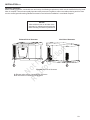
Generator Placement
Before installing generator, consult with user and convey the following requirements, which must be satisfied before the instal-
lation is complete. There are two equally important safety concerns in regards to carbon monoxide poisoning and fire. There
are also several general location guidelines that must be met before the installation is considered complete.
A B
A. Exhaust outlet section of weatherproof enclosure
B. Air inlet section of weatherproof enclosure
Figure 2 Overview of Generator
Exhaust Side of Generator Inlet Side of Generator
B

Not for
Reproduction
14
Carbon Monoxide Hazard Safety Placement Requirements
NOTICE
This section is for Carbon Monoxide Hazard Safety Placement Only. Satisfying the
generator placement requirements for the carbon monoxide hazard does not guarantee
that fire safety hazard placement requirements are met. Please refer to Fire Hazard
Safety Placement Requirements
INSTALLATION cont.
A
Figure 3 Carbon Monoxide Detector
F
C
D
B
G
E
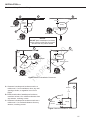
Figure 4 Carbon Monoxide Gas entries
The letters shown above in Figure 4 indicate POTENTIAL points of entry for Carbon Monoxide Gas.
A. Carbon Monoxide Detector(s): MUST be installed and maintained indoors according to
manufacturer’s instructions/recommendations.
Ensure exhaust gas is kept away from:
B. Windows
C. Doors
D. Ventilation Intakes
E.Sotvents
F. Garage doors
G. Crawl spaces or other openings that can allow exhaust gas to enter or be drawn into
potentially occupied building or structure.

Not for
Reproduction
15
INSTALLATION cont.
STANDBY
Generator
ENGINE
EXHAUST
Figure 5 Where Not to Place Generator
Trees, Shrubs
Trees, Shrubs
House
Back of House
All fossil fuel burning equipment, such as generators, contain
carbon monoxide (CO) gas in the engine exhaust. CO gas is
odorless, colorless, tasteless, and is unlikely to be noticed
until a person is overcome with carbon monoxide poisoning.
Breathing in CO gas can result in death. The following
requirements must be included as part of the generator
installation:
• Install generator outdoors in an area that will not
accumulate deadly exhaust gas.
• DO NOT install generator where exhaust gas could
accumulate and enter inside or be drawn into a
potentially occupied building or structure.
• Manufacturer requires a carbon monoxide detector(s)
in the home. Carbon monoxide detector(s) MUST
be installed and maintained indoors according to
manufacturer’s instructions/recommendations. A CO
detector is an electrical device that detects hazardous
levels of CO. When there is buildup of CO, the device
will alert the occupants by ashing visual indicator light
and alarm. Smoke alarms cannot detect CO gas. The
CO detector must comply with European Standard EN
50291 and carry the CE mark. The CE mark certies that
the CO detector is compliant with European Standards
for electrical safety.
• The neighbor’s home may be exposed to the
engine exhaust from the generator and must be
considered when installing the generator.
• Direct the generator exhaust away from or parallel to the
building or structure.
• DO NOT direct the generator exhaust towards a
potentially occupied building, structure, window, doors,
ventilation intakes, sot vents, crawl spaces, open
garage doors or other openings where exhaust gas
could accumulate and enter inside or be drawn into
potentially occupied building or structure.
• DO NOT place generator in any area where leaves or
debris normally accumulate.
• Position generator in an area where winds will carry the
exhaust gas away from any potentially occupied building
or structure.
• Place generator in a prepared location that is at and
has provisions for water drainage.
• Install the generator in a location where sump pump
discharge, rain gutter downspouts, roof run-o,
landscape irrigation, or water sprinklers will not ood the
generator or spray the enclosure and enter any air inlet
or outlet openings.
• Install the generator where it will not aect or obstruct
any services including covered, concealed and
underground, such as telephone, electric, fuel, irrigation,
air conditioning, cable, septic, sewer, well, etc.
• Install the generator where leaves, grass, snow, etc.
will not obstruct air inlet or outlet openings. If prevailing
winds will cause blowing or drifting, you may need to
construct a windbreak to protect the generator.
WARNING
Running engine produces carbon
monoxide, an odorless, poisonous gas.
Breathing carbon monoxide could result in
death, serious injury, headache, fatigue,
dizziness, vomiting, confusion, seizures, nausea
or fainting.
DO
• Do operate this product ONLY outdoors.
• Do keep exhaust gas away from any
windows, doors, ventilation intakes, soffit
vents, crawl spaces, open garage doors or
other openings that can allow exhaust gas
to enter inside or be drawn into a potentially
occupied building or structure.
• Do have carbon monoxide detectors
installed and maintained indoors
according to manufacturer’s instructions/
recommendations. Smoke alarms cannot
detect carbon monoxide gas.

Not for
Reproduction
16
INSTALLATION cont.
This side of page intentionally left blank
WARNING
Exhaust heat/gas could ignite
combustibles or structures resulting in death or
serious injury. Contact with muffler area could
cause burns resulting in serious injury. Before
installing and/or servicing fuel supply system:
DO
• Do allow equipment to cool before touching.
• Do avoid hot exhaust gases.
• Do locate the weatherproof enclosure a
minimum of 1.5 m from walls, windows,
doors, wall openings, shrubs, or vegetation
over 0.3 m in height.
• Do locate the weatherproof enclosure a
minimum of 1.5 m overhead clearance from
any structure, overhang or trees.
• Do ONLY use flexible fuel line provided.
Connect provided fuel line to generator.
• Do have smoke detectors installed
and maintained indoors according
to the manufacturer’s instructions/
recommendations. Carbon monoxide
detectors cannot detect smoke.
• Do allow sufficient room on all sides of
generator for maintenance and servicing.
DO NOT
• Do not use with or substitute the flexible
fuel line provided with any other fuel line.
• Do not place weatherproof enclosure under
a deck or any other type of structure that
may confine airflow.
• Do not touch hot parts.
• Do not smoke around generator.

Not for
Reproduction
17
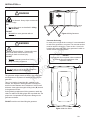
INSTALLATION cont.
A. Generator’s weatherproof enclosure must be a
minimum of 1.5 m from windows, doors, any wall
openings, shrubs, or vegetation over 0.3 m in
height.
B. Exhaust outlet side of weatherproof enclosure
must have at least 1.5 m minimum clearance from
any structure, overhang or trees.
C. Generator’s weatherproof enclosure must have a
minimum of 1.5 m overhead clearance from any
structure, overhang or trees.
Standby
Standby
Standby
Standby
Exhaust
Direction
Exhaust Direction
Exhaust
Direction
Exhaust Direction
46 cm min.
46 cm
min.
46 cm min.
NOTICE
DO NOT place weatherproof enclosure
under a deck or other type of covered
structure that may confine airflow
Figure 6 Minimum Installation Clearances
A
A
A
A
A
A
A
B
B
B
B
Trees, Shrubs
Trees, Shrubs
Trees, Shrubs
Trees, Shrubs
Trees, Shrubs
Trees, Shrubs
1.5 m
1.5 m
1.5 m
1.5 m
1.5 m
1.5 m
1.5 m
Structure
Center of Exhaust Panel
Standby
Exhaust
Direction
Figure 7 Minimum Installation Clearances
B
C
1.5 m
1.5 m
Fire Hazard Safety Placement Requirements

Not for
Reproduction
18
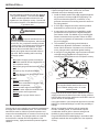
A
B
Figure 8 Electrical And Fuel Inlet Locations
25 mm
34 mm
35 mm
60 mm
INSTALLATION cont.
Electrical and Fuel Inlet Locations
The 3/4 inch NPT (National Pipe Thread – United States standard for tapered threads) fuel inlet (A) and electrical inlet
locations are shown in the figure below.
A knock-out is provided for the electrical inlet. This inlet may be enlarged or supplemented to accommodate a maximum
conduit size of 38 mm. Ensure that the installed conduit(s) enter the generator in the zone (B) shown in the figure below.
This will ensure they properly enter the electrical box and do not interfere with the fully opened roof.
NOTICE
DO use ONLY NPT (National Pipe Thread) standard pipe
threads for fuel inlet connection
DO NOT use BSPT (British Standard Pipe Thread) or any
other standard pipe threads other than manufacturer’s
recommendations for fuel inlet connection

Not for
Reproduction
19
INSTALLATION cont.
NOTICE
Concrete slab is not required unless mandated
by national rules and regulations of the
respective country
C
C
C
C
Figure 10 Anchor Holes
Figure 9 Lifting Generator
A
B
Lifting the Generator
The generator weighs more than 227kg. Use proper tools
and equipment in all phases of handling and moving the
generator.
Two 1.5 m lengths of steel pipe (A), supplied by the
installer, are required to lift the generator. Steel pipe to
be 25 mm outer diameter and a minimum of 2.5 mm wall
thickness. Insert pipes through the lifting holes (B) located
in the generator’s base.
If using hoisting equipment to lift the generator, attach the
chains or cables to the lifting pipes with a spreader bar. The
proper use of a spreader bar will prevent damage to the
generator enclosure.
DO NOT touch the roof when lifting the generator.
Concrete Anchoring
In areas prone to high winds or storms, it is recommended
to anchor the generator to concrete. The concrete anchors
must be rated to hold 363 kg. There are four 11 mm hole
locations (C) around the base of the generator in which to
anchor the unit. See figure below.
WARNING
Lift Hazard - Heavy object could result
in serious injury.
DO
• Do use lifting pipes as described in Lifting
the Generator.
DO NOT
• Do not lift or move generator without
assistance.
NOTICE
Do not lift unit by roof as this will damage the
generator and void warranty
WARNING
Electrical Shock - Contact with power
lines could cause electric shock or burns,
resulting in death or serious injury.
DO NOT
• Do not contact any power lines if using
lifting or hoisting equipment.

Not for
Reproduction
20
INSTALLATION cont.
A
B
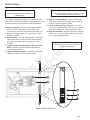
Roof Access
The roof access panel gives access to the control panel, air filter, oil dipstick, oil fill and circuit breaker.
Each generator is shipped with a set of identical keys. These keys fit in the lock on the front panel. The roof must be
unlocked in order for it to open.
To Open the Roof:
1. Insert key into lock (B) of front panel. Gently push down on roof above the lock to aid in turning the key one quarter turn
clockwise.
2. Lift roof (A) to the open position.
NOTICE
Roof should be kept locked at all times unless
servicing or maintaining generator
Figure 11 Front View
A. Roof
B. Lock
Page is loading ...
Page is loading ...
Page is loading ...
Page is loading ...
Page is loading ...
Page is loading ...
Page is loading ...
Page is loading ...
Page is loading ...
Page is loading ...
Page is loading ...
Page is loading ...
Page is loading ...
Page is loading ...
Page is loading ...
Page is loading ...
-
 1
1
-
 2
2
-
 3
3
-
 4
4
-
 5
5
-
 6
6
-
 7
7
-
 8
8
-
 9
9
-
 10
10
-
 11
11
-
 12
12
-
 13
13
-
 14
14
-
 15
15
-
 16
16
-
 17
17
-
 18
18
-
 19
19
-
 20
20
-
 21
21
-
 22
22
-
 23
23
-
 24
24
-
 25
25
-
 26
26
-
 27
27
-
 28
28
-
 29
29
-
 30
30
-
 31
31
-
 32
32
-
 33
33
-
 34
34
-
 35
35
-
 36
36


Simplicity 040490-00 Installation guide
- Category
- Power generators
- Type
- Installation guide
Ask a question and I''ll find the answer in the document
Finding information in a document is now easier with AI
Related papers
Other documents
-
General Electric HOME GENERATOR SYSTEM 13000 WATT Owner's manual
-
Briggs & Stratton 040638 Installation guide
-
Briggs & Stratton 040646 Installation guide
-
Briggs & Stratton 40234 User manual
-
-
-
-
Briggs & Stratton 040346-00 Installation guide
-
Kohler 20RESC Installation guide
-
 Barn Pros THD-BP2CARG User manual
