
General
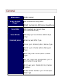
Attenuation
20dB nominal
Audio Output
Power
3W nominal into 8Ω speaker
30mW nominal into 32Ω stereo headphone
Scan Rate
100 channels per second max
(Conventional mode)
Search Rate
300 steps per second max (5kHz steps
only)
External Jacks
Antenna Jack: BNC Type
Phone Jack: 3.5mm (1/8 in.) Stereo Type
Ext.SP Jack: 3.5mm (1/8 in.) Monaural
Type
REC.Out Jack: 3.5mm (1/8 in.) Stereo
Type
Ext. DC Power and Orange Wire Jack 3
pin (Center Orange Wire)
DC Power Jack: 5.5mm (1/5 in.) (Center
Positive)
GPS/Remote Interface Jack: D Sub 9pin
Male Type

Remote Interfase Jack (front panel): 4-pin
Mini Custom Type
Internal Speaker
8.0Ω 5.0W Max. 77mm (3.0 in.)
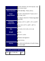
Power
Requirements
DC:11V to 16.6V(Ext.DC Power Jack or
DC Power Jack)
AC Adapter (13.8V DC 750mA Regulated)
(AD-1009)
Operating
Temperature
Nominal: -20°C to +60°C -4°F to +140°F
Close Call: -10°C to +60°C +14°F to
+140°F
Size
7.2 in.(W) x 5.9 in.(D) x 2.2 in.(H)
Weight
3.42 lbs
Remote Functions
Direct PC control
Database management
Wired cloning
Display
64 x 128 Full Dot Matrix LCD with Orange-
color back light
Sensitivity (nominal) 12dB SINAD
0.4μV
25-27.995 MHz
AM

0.3μV
28-53.98 MHz
NFM
0.6μV
54-71.95 MHz
WFM
0.2μV
72-75.995 MHz
FM
0.5μV
76-107.9 MHz
FMB
0.3μV
108-136.9916 MHz
AM
0.3μV
137-173.9875 MHz
NFM
0.5μV
174-215.95 MHz
WFM
0.3μV
216-224.98 MHz
NFM
0.3μV
225-379.975 MHz
AM
0.3μV
380-512 MHz
NFM
0.3μV
758-960 MHz
NFM
0.4μV
1240-1300 MHz
NFM
Signal Noise Ratio (nominal)
48dB
25-27.995 MHz
AM
41dB
28-53.98 MHz
NFM
54dB
54-71.95 MHz
WFM

48dB
72-75.995 MHz
FM
60dB
76-107.9 MHz
FMB
50dB
108-136.9916 MHz
AM
41dB
137-173.9875 MHz
NFM
54dB
174-215.95 MHz
WFM
41dB
216-224.98 MHz
NFM
50dB
225-379.975 MHz
AM
40dB
380-512 MHz
NFM
41dB
758-960 MHz
NFM
37dB
1240-1300 MHz
NFM
Close Call Sensitivity (nominal)
160μV
VHF Low1 Band
110μV
VHF Low2 Band
90μV
Air Band
90μV
VHF High1 Band
100μV
VHF High2 Band

110μV
UHF Band
160μV
800MHz+ Band
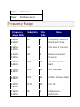
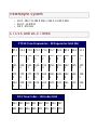
Frequency Range
Frequency
Range (MHz)
Modulation
Step
(kHz)
Name
25.0000-
26.9600
AM
5
Petroleum Products &
Broadcast Pickup
26.9650-
27.4050
AM
5
CB Class D Channel
27.4100-
27.9950
AM
5
Business & Forest
Products
28.0000-
29.6800
NFM
20
10 Meter Amateur
Band
29.7000-
49.9900
NFM
10
VHF Low Band
50.0000-
53.9800
NFM
20
6 Meter Amateur Band
54.0000-
71.9500
WFM
50
VHF TV
72.0000-
75.9950
FM
5
Intersystem &
Astronomy

76.0000-
87.9500
WFM
50
VHF TV
88.0000-
107.9000
FMB
100
FM Broadcast
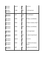
108.0000-
136.9916
AM
8.33
Aircraft Band
137.0000-
143.9875
NFM
12.5
Military Land Mobile
144.0000-
147.9950
NFM
5
2 Meter Amateur Band
148.0000-
150.7875
NFM
12.5
Military Land Mobile
150.8000-
161.9950
NFM
5
VHF High Band
162.0000-
173.9875
NFM
12.5
Federal Government
174.0000-
215.9500
WFM
50
VHF TV
216.0000-
224.9800
NFM
20
1.25 Meter Amateur
Band
225.0000-
379.9750
AM
25
Military Aircraft Band

380.0000-
399.9875
NFM
12.5
Military Land Mobile
400.0000-
405.9875
NFM
12.5
Miscellaneous
406.0000-
419.9875
NFM
12.5
Federal Government
Land Mobile
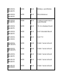
420.0000-
449.9875
NFM
12.5
70 cm Amateur Band
450.0000-
469.9875
NFM
12.5
UHF Standard Band
470.0000-
512.0000
NFM
12.5
UHF TV
758.0000-
787.99375
NFM
6.25
Public Service Band
788.0000-
805.99375
NFM
6.25
Public Service Band
806.0000-
823.9875
NFM
12.5
Public Service Band
849.0125-
868.9875
NFM
12.5
Public Service Band
894.0125-
960.0000
NFM
12.5
Public Service Band

1240.0000-
1300.0000
NFM
25
25 cm Amateur Band
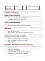
Special Functions
Band Scope Function
Frequency Span 0.2 MHz To 500 MHz
Frequency Step 5 kHz To 100 kHz
Two-Tone-Sequential
250.0-3500.0Hz , 0.1Hz Step Programmable
WX Alert
1050 Hz Tone System
NWR-SAME System (Warning / Watch / Advisory)
Supported trunking systems
Motorola Systems: Type I, II, II/I (hybrid)
EDACS Systems: FM, NFM, and SCAT
LTR Systems
Dynamic memory allocation capacity
Systems: 500 max
Groups: 20 per system
Site: 1000 max (All) 256 per system
Channels: 9000 max (21120 memory blocks)
Channels per Trunked System: 500 max

Heterodyne System
1st IF: 380.7 to 380.8 MHz / 265.5 to 265.6 MHz
2nd IF: 10.8 MHz
3rd IF: 450 kHz
CTCSS and DCS Tones
CTCSS Tone Frequencies - 50 frequencies total (Hz)
67.0
69.3
71.9
74.4
77.0
79.7
82.5
85.4
88.5
91.5
94.8
97.4
100.
0
103.
5
107.
2
110.
9
114.
8
118.
8
123.
0
127.
3
131.
8
136.
5
141.
3
146.
2
151.
4
156.
7
159.
8
162.
2
165.
5
167.
9
171.
3
173.
8
177.
3
179.
9
183.
5
186.
2
189.
9
192.
8
196.
6
199.
5
203.
5
206.
5
210.
7
218.
1
225.
7
229.
1
233.
6
241.
8
250.
3
254.
1
DCS Tone Codes - 104 codes total
023
025
026
031
032
036
043
047
051
053
054
065
071
072
073
074

114
115
116
122
125
131
132
134
143
145
152
155
156
162
165
172
174
205
212
223
225
226
243
244
245
246
251
252
255
261
263
265
266
271
274
306
311
315
325
331
332
343
346
351
356
364
365
371
411
412
413
423
431
432
445
446
452
454
455
462
464
465
466
503
506
516
523
526
532
546
565
606
612
624
627
631
632
654
662
664
703
712
723
731
732
734
743
754
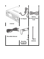
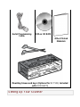
Included With Your Scanner

Scanner
AC Adapter
Vehicle
Accessory Power
Cord
Three-Wire Harness
Mounting
Bracket and
Hardware
Antenna


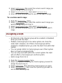
These guidelines will help you install and set up your new scanner:
The scanner can be placed on a convenient surface in your home
as a base station, and connected to a standard outlet that supplies
120VAC, 60Hz. You must use either the supplied antenna or an
electrically correct outdoor antenna, properly and safely mounted at
your chosen site.
The scanner is also designed to accommodate either DIN-E and
ISO-DIN automotive mounting configurations using a DIN-E sleeve
and keys, (Part Number DIN-0001, BCD996XT: Included; BCT15X:
Optional).
The unit can also be placed above, beneath, or in the dash of your
vehicle using the supplied bracket and mounting hardware.
If your scanner receives interference or electrical noise, move
the scanner or its antenna away from the source.
To improve the scanner’s reception, use an optional external
antenna designed for multi-band coverage. (You can purchase
this type of antenna at a local electronics store). If the optional
antenna has no cable, use 50Ω coaxial cable for lead-in. A
mating plug might be necessary for the optional antennas.
Use an optional stereo earphone or sterreo headset with
proper impedance (32 Ω) for private listening. Read the
precautions at General Precautions.
Do not use the scanner in high-moisture environments such as
the kitchen or bathroom.
Avoid placing the scanner in direct sunlight or near heating
elements or vents.
Power Related Issues
Important: To prevent memory from being corrupted, do not unplug
the AC adapter during the time the memory is accessed for
programming or auto store.

Notes:
If when you connect the AC adapter the [VOL] /Power Switch
is ON, the scanner may not power on. Should this occur,
simply turn the control OFF, then ON again.
If the scanner loses power (as when you turn off your car’s
ignition with the scanner’s power switch on), it can lose some
system settings such as display color and backlight. To ensure
that such settings persist, either change the setting using the
scanner’s menu or power the scanner off then back on using
the power switch after making such setting changes.
When you turn off the scanner using the power switch, the scanner
remembers the last settings and mode. When you turn power back
on, it resumes the previous mode.
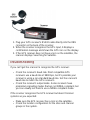
Base Station
This is the simplest approach to let you get started quickly. Decide
on a location that is convenient to a nearby wall outlet, has desk
space to let you complete your programming worksheets, will safely
allow the indoor antenna to be extended, or near a window to use
an outdoor antenna.
To secure the radio to a surface, by means of the mounting bracket,
follow the steps below:

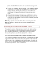
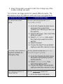
1. Attach the four protective mounting feet to the mounting
bracket when you casually use the scanner on a flat surface.
Should you desire to permanently mount the scanner, remove
the feet and use wood screws through the bracket as
described in Steps 2 and 3.
2. Use the bracket as a template to mark positions for the two
mounting screws.
3. At the marked positions, drill holes slightly smaller than the
screws.
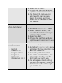
4. Align the bracket with the threaded holes on the sides of the
radio case so the bracket is beneath the radio. Secure the
bracket using the two threaded knobs. Never overtighten the
knobs.
Once the radio is positioned, connect it to a source of AC power
using the supplied 13.8V, 750 mA AC adapter. Insert the barrel of
the AC adapter to the jack on the rear, upper right side of the radio
marked. Insert the connector of the supplied indoor telescoping
antenna to the BNC Antenna Connector and apply moderate
pressure to secure it.
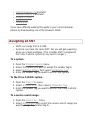
Setting Up an Audio Recording Device or
Computer Recording
It is best if you plan ahead when you initiate the basic setup of the
scanner if you include the components to record incoming
reception. You need an audio recording device which can be
controlled by a Voice Operated module (VOX) either externally or
from within the unit and the correct connecting cable. The REC
(record) jack on the rear apron provides a constant-level audio
output which is not affected by the setting of the volume control.
Use a mono or stereo cable that ends in a 3.5mm plug for the
scanner. The recorder might have its own requirements as to the
proper plug. Check the recorder’s instructions to be sure. Connect
the cable to an external or internal VOX control so that the recorder
operates when audio is present.

You can also connect the cable to the appropriate input jack on your
PC so that with controlling software, you can record to your hard
disk.
In order for the function to operate, you must set the channel to
record. You must also set the system’s record option to either All
Channel, which will record all channels regardless of any channel’s
setting, or Marked Channel which only lets recording occur if you
have selected record for that channel. Which you choose will
depend on various factors.
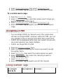
Vehicle Installation
You can mount your scanner in your vehicle, using either the
supplied bracket or the optional DIN-E sleeve.
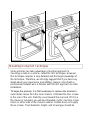
Mounting Using the Bracket
With the bracket removed from the radio, use the holes in the
bracket as a template to initially mark the location you plan to use in
your vehicle. Be absolutely certain of what might be behind the
mounting surface before making any holes, be it above, or below, or
in front of your dash, armrest console, or other location. If you drill
carelessly, expensive damage can result. If in doubt, consult your
vehicle dealer’s service department or a qualified professional
installer.
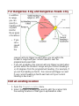
Important: AVOID AIRBAG DEPLOYMENT ZONES. Ignoring this
installation concern may result in bodily harm and the inability of the
airbag to perform properly.

1. Using appropriate screws or other hardware, secure the
bracket.
2. Insert the scanner and insert the bracket knobs to lock the
scanner in position.
3. Attach the Cigarette Lighter Power Cord to the rear of the
scanner and plug the adapter end into a dash mounted 12V
DC socket.
4. Attach a suitable mounted mobile antenna to the antenna jack
on the back of the scanner.

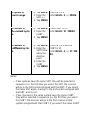
Mounting Using the DIN-E Sleeve (Option for BCT15X)
If you are unsure about how to install your scanner in your vehicle
using the optional DIN-E sleeve, consult your automobile
manufacturer, dealer, or a qualified installer. Before installing,
confirm that your scanner fits in the desired mounting area and you
have all the necessary materials to complete the task. Your scanner
requires a 2 x 7-1/8 x 5-5/16 inch (50 x 180 x 135 mm) mounting
area. Allow an additional 2-3/8 inch (60mm) space behind the unit
for connectors and wires.
To purchase the DIN-E sleeve and included Removal Keys,
visit http://www.unidendirect.com/ and order part number, DIN-0001.

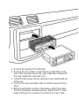
1. Remove the bracket if it is attached.
2. Remove the four Philips screws from four small tabs on the
rear of the case that secure the outer metal case and pull off
the case (toward the rear) with care.
3. Install the DIN sleeve into the opening in your dashboard, lip
facing out.
4. Push out the top and bottom tabs to hold the sleeve firmly in
place.
5. Before inserting the scanner in the sleeve, attach the cable
from the previously mounted antenna. Attach the DC Power
leads. RED goes to a positive (+)connection on your fuse

block while BLACK connects to the vehicle’s chassis ground (-
).
6. Connect the ORANGE lead to one side of the headlamp switch
so that when you activate the headlights, the scanner’s LCD
display changes intensity. Be sure all the connections are
routed away from any potentially pinching or slicing sheet
metal.
7. Slowly slide the scanner into the sleeve until it locks in place.
8. To remove the unit, fully insert the removal keys into each slot
on the left and right edges of the front panel. Carefully slide the
radio from the sleeve.
Note: If you plan to connect a GPS unit or external speaker at a
later time, expect to remove the unit for ease of making those
connections.
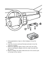
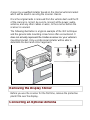
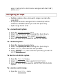
Removing the Scanner from the DIN-E Sleeve
If you plan to connect other devices or wires to the radio, such as a
GPS unit, at a later time, you should plan to remove the scanner
from the DIN-E sleeve. This is easily done using the provided
Removal Keys that come with the optional DIN-E sleeve.
Refer to the illustration that follows, showing the Removal Keys.
Fully insert both Removal Keys into the slots on the left and the right
edges of the radio’s dress panel. You cannot remove the radio with
only one key. Press in fully,and do not twist the keys. The radio will
unlock from the sleeve making withdrawal from the sleeve possible.
Store the keys in a safe place for future use.
Page is loading ...
Page is loading ...
Page is loading ...
Page is loading ...
Page is loading ...
Page is loading ...
Page is loading ...
Page is loading ...
Page is loading ...
Page is loading ...
Page is loading ...
Page is loading ...
Page is loading ...
Page is loading ...
Page is loading ...
Page is loading ...
Page is loading ...
Page is loading ...
Page is loading ...
Page is loading ...
Page is loading ...
Page is loading ...
-
 1
1
-
 2
2
-
 3
3
-
 4
4
-
 5
5
-
 6
6
-
 7
7
-
 8
8
-
 9
9
-
 10
10
-
 11
11
-
 12
12
-
 13
13
-
 14
14
-
 15
15
-
 16
16
-
 17
17
-
 18
18
-
 19
19
-
 20
20
-
 21
21
-
 22
22
-
 23
23
-
 24
24
-
 25
25
-
 26
26
-
 27
27
-
 28
28
-
 29
29
-
 30
30
-
 31
31
-
 32
32
-
 33
33
-
 34
34
-
 35
35
-
 36
36
-
 37
37
-
 38
38
-
 39
39
-
 40
40
-
 41
41
-
 42
42


Ask a question and I''ll find the answer in the document
Finding information in a document is now easier with AI
Related papers
Other documents
-
INTEK AR-109 Owner's manual
-
Radio Shack PRO-197 User manual
-
 ADI WFM User manual
-
-
Radio Shack Pro-2045 User manual
-
 Whistler Group WS1065 User guide
-
Realistic PRO-2006 Owner's manual
-
-
-
 Whistler Group WS1040 User guide


