Page is loading ...

AGP Pellet Insert
• Masonry Fireplace
• Factory-Built (Metal)Fireplace
• Mobile Home Approved
-- Please read this entire manual before
installation and use of this pellet fuel-
burning room heater. Failure to follow
these instructions could result in
property damage, bodily injury, or even
death.
-- Contact local building or fire officials
about restrictions and installation
inspection requirements in your area.
-- Save these instructions.
Tested and Listed by:
ASTM E1509-4 ULC-S628
Installer: After installation give this manual to the home-
owner and explain operation of this insert.
Consumer: Retain this manual for future reference.
$10.00 Copyright 2018, T.I.
Part # 100-01341 11/15/18
Travis Industries, Inc.
www.travisproducts.com
12521 Harbour Reach Drive
Mukilteo, WA 98275

2 Introduction
© Travis Industries 11/15/18 - 1341 AGP Insert
Introduction
We welcome you as a new owner of an AGP pellet insert. In purchasing an AGP pellet insert you
have joined the growing ranks of concerned individuals whose selection of an energy system reflects
both a concern for the environment and aesthetics. The AGP pellet insert is one of the finest home
heaters the world over. This manual will explain the installation, operation, and maintenance of this
pellet-burning heater. Please familiarize yourself with this Owner's Manual before operating your
heater and save the manual for future reference. Included are helpful hints and suggestions which
will make the installation and operation of your new heater an easier and more enjoyable experience.
We offer our continual support and guidance to help you achieve the maximum benefit and enjoyment
from your heater.
Important Information
No other AGP pellet insert has the same serial number
as yours. The serial number is on the safety label on
the back of the appliance.
This serial number will be needed in case you require
service of any type.
Model: AGP PI
Serial Number:
Purchase Date:
Purchased From:
Register your warranty online at:
traviswarranty.com
Save Your Bill of Sale.
To receive full warranty coverage, you will need to
show evidence of the date you purchased your
heater.
We suggest that you attach your Bill of Sale to this
page so that you will have all the information you
need in one place should the need for service or
information occur.

Table of Contents 3
© Travis Industries 11/15/18 - 1341 AGP Insert
Introduction .............................................................. 2
Important Information .............................................. 2
Heating Specifications ............................................. 7
Dimensions ............................................................... 7
Electrical Specifications .......................................... 7
Fuel ............................................................................ 7
Emissions ................................................................. 7
Efficiency .................................................................. 7
Before You Begin ..................................................... 8
Packing List .............................................................. 8
Items Required ......................................................... 8
Installation Options .................................................. 8
Planning the Installation .......................................... 9
Minimum Fireplace Size .......................................... 9
Fireplace Damper ..................................................... 9
Electrical Requirements ........................................ 10
Hopper Extension Set-up ...................................... 11
Hopper Extension Setup ..................................... 12
Clearances .............................................................. 13
Venting the Pellet Insert ........................................ 14
Maximum Venting Distance: ............................... 14
Pellet Vent Type .................................................. 14
Installing the Pellet Vent ..................................... 14
Travis Vent Kits ................................................... 15
Mobile Home Requirements .................................. 16
Outside Air (Used for Combustion Use Part
#99200136) .............................................................. 16
Detachable Vent Connector .................................. 17
Connecting the Vent to the Vent Connector ........ 17
Restrictor Adjustment ........................................... 18
Surround Panel & Control Panel Installation &
Removal .................................................................. 19
Installation into a Masonry Fireplace ................... 23
Installation into a Factory-Built (Metal) Fireplace 24
Safety Notice .......................................................... 25
Location of Controls .............................................. 25
Loading Pellets ....................................................... 26
Starting the Heater for the First Time ................... 26
Curing the Paint .................................................. 26
Manual Mode .......................................................... 27
To Start ................................................................... 27
To Shut Down ......................................................... 27
To Adjust the Heat .................................................. 27
To Adjust the Fan .................................................... 28
Auto-Fan ................................................................. 28
TSTAT (Thermostat) Mode .................................... 29
To Start the Insert in TSTAT Mode ......................... 29
To Adjust the Heat Output ....................................... 29
To Shut Down ......................................................... 29
Changing the TSTAT Program ............................ 30
How to Tell Which TSTAT Program You Are In ...... 30
Switching Between Program 1, 2, and 3 ................. 30
Thermostat Program 1 ............................................ 30
Thermostat Program 2 ............................................ 30
Thermostat Program 3 ............................................ 30
Start-Up Sequence (Igniter) ................................... 3 1
Power Outages ....................................................... 31
Manual Mode .......................................................... 31
TSTAT Mode ........................................................... 31
Normal Operating Sounds ..................................... 31
Insert Maintenance ................................................. 32
Maintenance Schedule ....................................... 32
Removing Flyash ................................................ 32
Disposal of Ashes ............................................... 32
Insert Maintenance Tools .................................... 33
Opening the Door ................................................ 33
Inspect the Burn .................................................. 33
Cleaning the Fire Platform .................................. 34
Cleaning the Heat Exchange Tubes ................... 37
Cleaning the Glass .............................................. 38
Emptying the Ashpan .......................................... 38
Cleaning Behind the Firebox Liners .................... 39
Cleaning the Exhaust Duct.................................. 40
Access and Clean Components .......................... 41
Clean the Exhaust Blower ................................... 41
Cleaning the Convection Blower .......................... 43
Cleaning the Negative Pressure Tube ................ 44
Cleaning the Vent ............................................... 44
Adjusting the Door Cam ...................................... 45
Checking for Air Leaks ........................................ 4 5
Every Two Years (or Every 4 to 6 Tons of
Pellets) Chisel Replacement ............................ 45
Troubleshooting Table .......................................... 46
Replacement Parts ................................................. 46
Door Parts ........................................................... 46
Wiring Diagram ....................................................... 47
Thermostat Installation .......................................... 51

4
Installation (For Qualified Installers Only)
© Travis Industries
4070806 100-01191_000
HOT WHILE IN OPERATION.
KEEP CHILDREN, CLOTHING,
AND FURNITURE AWAY.
CONTACT MAY CAUSE SKIN
BURNS.
Educate all children of the danger of
a high-temperature heater. Young
children should be supervised when
they are in the same room as the
heater.
Contact your local building officials
to obtain a permit and information
on any installation restrictions or
inspection requirements in your
area. Notify your insurance
company of this appliance as well.
Do not operate the heater if you
smell smoke coming from the
heater. Press the “STOP" button,
monitor your heater, and call your
dealer.
Never use gasoline, gasoline-type
lantern fuel, kerosene, charcoal
lighter fluid, or similar liquids to start
or “freshen up” a fire in this heater.
Keep all such liquids well away from
the heater while it is in use.
Do not store solid fuel or place such
fuel within heater installation
clearances or within the space
required for charging and ash
removal.
Do not unplug the heater if you
suspect a malfunction. Press the
“STOP" button and periodically
inspect the heater.
Ashes should be placed in a metal
container with a tight-fitting lid. The
closed container of ashes should be
placed on a noncombustible floor or
on the ground, well away from all
combustible materials, pending final
disposal. If the ashes are disposed of
by burial in soil or otherwise locally
dispersed, they should be retained in
the closed container until all cinders
have been thoroughly cooled.
Never try to repair or replace any
part of the heater unless
instructions are given in this
manual. All other work should be
done by a trained technician.
Do not alter this appliance in any
way.
The viewing door and ashpan must
be closed and latched during
operation.
This unit must be properly installed
to prevent the possibility of a house
fire. The instructions must be strictly
adhered to. Do not use makeshift
methods or compromise in the
installation.
This heater is designed and approved
for pelletized wood fuel only.
Ok
Gas
ASHES

Installation (For Qualified Installers Only)
5
© Travis Industries 11/15/18 - 1341 AGP Insert
Allow the appliance to cool
completely before carrying out any
maintenance or cleaning.
Maintain the door and glass seal
and keep them in good condition.
Do not operate this heater with
broken or missing glass.
Do not slam the door or strike the
glass.
Notify your dealer to replace the
glass if glass on this appliance is
broken or damaged.
Do not operate the heater if the
flame becomes dark and sooty or if
the fire platform overfills with
pellets. Press the “STOP” button
and periodically inspect the heater.
Do not place clothing or other
flammable items on or near this
appliance.
The heater will not operate during a
power outage.
This heater must be connected to a
standard115 V., 60 Hz grounded
electrical outlet. Do not use an
adapter plug or sever the grounding
plug. Do not route the electrical cord
underneath, in front of, or over the
heater.
Keep foreign objects out of the
hopper.
The exhaust system must be
completely airtight and properly
installed. The pellet vent joints must
be sealed with RTV 500 F. (260 C.)
silicone sealant.
Your heater requires periodic
maintenance and cleaning (see
"Insert Maintenance"). Failure to
maintain your heater may lead to
accumulation of soot, creosote, and
ash, and smoke spillage or fire in
your home.
When installed in a mobile home,
the heater must be bolted to the
floor, have outside air, and NOT BE
INSTALLED IN THE BEDROOM
(per H.U.D. requirements). Check
with local building officials.

6
Installation (For Qualified Installers Only)
© Travis Industries
4070806 100-01191_000
Do not throw this manual away.
This manual has important
operating and maintenance
instructions that you will need at a
later time. Always follow the
instructions in this manual.
Disconnect the power before
performing any maintenance.
The exhaust system should be
checked at least twice a year for
any build-up of soot or creosote.
Travis Industries, Inc. grants no
warranty, implied or stated, for
the installation or maintenance of
your appliance, and assumes no
responsibility of any
consequential damage(s).
DO NOT INSTALL A FLUE DAMPER IN THE EXHAUST VENTING SYSTEM OF THIS UNIT.
DO NOT CONNECT THIS UNIT TO A CHIMNEY FLUE SERVING ANOTHER APPLIANCE.
INSTALL VENT AT CLEARANCES SPECIFIED BY THE VENT MANUFACTURER.
Soot and Flyash: Formation and Need for Removal – The products of combustion will contain
small particles of flyash. The flyash will collect in the exhaust venting system and restrict the
flow of the flue gases. Incomplete combustion, such as occurs during startup, shutdown, or
incorrect operation of the room heater will lead to some soot formation which will collect in
the exhaust venting system. The exhaust venting system should be inspected at least twice
every year to determine if cleaning is necessary.
NEVER USE SUBSTITUTE MATERIALS FOR ANY PURPOSE ON THIS APPLIANCE.
Establish a routine for the fuel, wood burner and firing technique. Check for creosote build-up
daily until you know how often to clean the appliance for safe operation. Be aware that the
hotter the fire, the less creosote is deposited, and weekly cleaning may be necessary in mild
weather even though monthly cleaning may be enough in the coldest months. Contact your
municipal or provincial fire authority for information on how to handle a chimney fire. Have a
clearly understood plan in place for how to handle a chimney fire.
Do not burn this insert if unburned pellets are in the ashpan. These should be removed as they
may ignite.
Smoke and CO Detectors: Make sure your home has a working smoke detector, especially near any bedrooms. We
recommend having a smoke and/or CO detector in the same room as the wood heater for additional safety.
Proposition 65 Warning: Fuels used in gas, woodburning or oil fired appliances, and the products of combustion of such fuels,
contain chemicals known to the State of California to cause cancer, birth defects and other reproductive harm.
California Health & Safety Code Sec. 25249.6
This wood heater has a manufacturer-set minimum low burn rate that must not be altered. It is against federal regulations to
alter this setting otherwise operate this wood heater in a manor inconsistent with operating instructions in this Manual.
U.S. and Foreign Patents Pending.
This
Manual

Installation (For Qualified Installers Only)
7
© Travis Industries 11/15/18 - 1341 AGP Insert
Heating Specifications
Approximate Maximum Heating Capacity (in square feet)* ............................................ 800 to 2,000 Sq. Feet
BTUs .............................................................................................................................. 11,480 to 41,000 **
Burn Rate (Pounds per Hour)*** .................................................................................... 1.4 to 5
Maximum Burn Time on Low Burn*** ............................................................................. 28 to 50 Hours
Hopper Capacity ............................................................................................................ 40 to 70 Pounds
Turn-Down Ratio ............................................................................................................ 71%
* Heating capacity will vary depending on the home's floor plan, degree of insulation, and the outside temperature. It is also affected by the fuel
size, quality, and moisture level.
** Based on 8,200 BTUs per pound.
*** Small pellet size will decrease the stated burn rates and burn times. Differences of plus or minus 20% depending on fuel quality may occur.
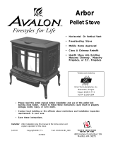
Dimensions
Electrical Specifications
Electrical Rating ...................................................................................................... 115 Volts, 3 Amps, 60 Hz
Watts during Start-Up Sequence ............................................................................ 350 (approximately)
Watts during Operation ........................................................................................... 250 (approximately)
Fuel
This heater is designed and approved for pelletized wood fuel only (all grades).
Travis Industries Inc.
recommends using only fuel that is certified by the Pellet Fuels Institute (PFI).
Emissions
This heater meets the 2020 U.S. EPA’s emission limits for pellet stoves. Report# 0028PN108E Tested to ASTM
E2779-10, ASTM 2515-11, CSA B415.1-10 this heater has been shown to deliver heat at rates ranging from 12,138 to
41,758 BTU/hr and an emission value of 0.98g/h.BTU/hr
Efficiency
This model was tested for efficiency using method B415.1-10 and was determined to have a weighted
average higher heating Value (HHV) Overall Heating Efficiency (OHE) of 75.6%. Overall efficiency of the
heater may be lower if the heater is operated with the heat exchange blower on low.
3" (77mm) Dia. Exhaust
1.75" (45mm) Dia. Intake
Fireplace Opening
33.25" (845mm) Min. Fireplace Width
14.25" (362mm)
Min. Fireplace Depth
10" (254mm)
Extension Onto Hearth
Centerline
24.75" (629mm)
42" (1067mm)
Control Panel
24" (610mm) Maximum
Hopper Setting (70 lb.)
21" (534mm) MInimum
Hopper Setting (40 lb.)
26"
(661mm)
30.5"
(775mm)
Front of Firebox
(for measuring hearth requirement)
11.5"
293mm
8.375" 213mm
8.375"
213mm
21.75" (553mm)

8 Installation (For Qualified Installers Only)
© Travis Industries 4070806 100-01191_000
Before You Begin
READ THIS ENTIRE MANUAL BEFORE YOU INSTALL AND USE THIS HEATER.
FAILURE TO FOLLOW THE INSTRUCTIONS MAY RESULT IN PROPERTY
DAMAGE, BODILY INJURY, OR EVEN DEATH.
Check with local building officials for any permits required for installation of this pellet heater and
notify your insurance company before proceeding with installation.
Packing List
(9) Screws for Hopper Lid
Items Required
AGP Pellet Insert Side Panels (SKU 94400030, 94400031, or 94400032)
Installation Options
This insert must be installed into a clean undamaged fireplace . Fireplace must be:
Masonry Fireplace (Code-Conforming UBC Masonry Fireplace)
- or -
Factory Built (Metal) Fireplace
Cleaning tool
Brush
Bottle Brush
Fuses

Installation (For Qualified Installers Only) 9
© Travis Industries 11/15/18 - 1341 AGP Insert
Planning the Installation
HINT: Have an authorized Travis Industries dealer install this heater. If you install the
heater yourself, have your dealer review your installation plans.
HINT: Inspect the chimney and clean as necessary before installing the heater. NOTE: The
convection blower is open to the fireplace cavity and may circulate odors from the
fireplace. You may wish to paint the interior of the fireplace with latex paint to
prevent odors from entering the home.
The location of your wood heater in your home will decide how affectively the heat produced will
spread throughout your house. Attention to the home design with consideration of natural convection
and air circulation should be taken into account when choosing the placement of your heater within
the home.
Minimum Fireplace Size
Fireplace Damper
Any existing damper must be removed or locked in the open position.
Min. 33.25" (845mm)
(includes circuit board)
Min. 21"
(534mm)*
Mantel
(combustible or non-combustible)
Min. 36.75" (934mm)
6" (153mm) from hopper lid
Non-Combustible Hearth
(Spark Protection Only)
Min. 14.25"
(362mm)
Min. 36" (915mm)
*Hopper Cover may be raised to 24"
(610mm) to accommodate a larger hopper.
Min. 16" (407mm)
6" (153mm) from firebox front
Min. 21.75" (553mm)

10 Installation (For Qualified Installers Only)
© Travis Industries 4070806 100-01191_000
Electrical Requirements
This heater requires a standard 120 volt, 60 Hz grounded electrical outlet. Do not use an
adapter plug or sever the grounding plug.
This heater requires correct polarity. The line (hot) is on the right and has a smaller plug. The
neutral (common) is on the left and has a larger plug. Use a circuit tester (available at hardware
stores) or contact an electrician to verify correct polarity and grounding.
WARNING: CONNECTION TO A REVERSE POLARITY OR UN-GROUNDED CIRCUIT MAY
DAMAGE YOUR HEATER’S CIRCUIT BOARD. THIS MAY CAUSE A SAFETY HAZARD,
IMPROPER OPERATION, AND VOID YOUR WARRANTY.
Do not route the electrical cord underneath, in front of, or over the heater.
HINT: Travis Industries manufactures a Insert Wiring Kit (97200315) that allows the power cord to
be routed through the fireplace, concealing the power cord.

Installation (For Qualified Installers Only) 11
© Travis Industries 11/15/18 - 1341 AGP Insert
Hopper Extension Set-up
This pellet insert has a variable-height hopper. On large fireplaces (24” or greater height) the hopper may
be extended to the upper position, increasing hopper capacity. On smaller fireplaces (under 24” fireplace
height) the hopper top may be placed in a lower position.
Use the chart below to determine the hopper extension position.
Hopper Extension Position
Hopper Height
A Lowest Position 21”
B Mid-Low 21.75”
C Middle Position 22.5”
D Mid-High 23.25”
E Highest 24”
The hopper extends 14.25” into the fireplace. For determining the maximum hopper extension,
measure the fireplace 14.25” into the fireplace.
The hopper top is shipped attached to the hopper assembly with shipping screws. Follow the instructions
below to attach the hopper top to the hopper assembly using the screws included in the owner’s pack.
Determine the correct hopper extension based on the table below.
A
B
C
D
E
Shipping Screw (both sides)

12 Installation (For Qualified Installers Only)
© Travis Industries 4070806 100-01191_000
Hopper Extension Setup
1 Remove the two shipping screws on each side of the insert (see illustration on previous page).
2 Remove the hopper top.
3 Use a center-punch to remove the appropriate knock-outs from the hopper walls (9 total). The
holes are punched out from the inside. Make sure to support the hopper walls while removing the
knock-outs. In the example below the “A” position is used (tallest hopper position).
4 Place the hopper top over the hopper assembly. Line up the holes in the hopper top with the
holes on the hopper assembly. Use the 9 screws included in the owner’s pack to secure the
hopper top to the hopper assembly.

Installation (For Qualified Installers Only) 13
© Travis Industries 11/15/18 - 1341 AGP Insert
Clearances
• Insert must be placed so that no combustibles are within, or can swing within (e.g. drapes, doors),
36" (915mm) of the front of the heater.
• Insert must be placed a minimum 9"
(229mm) from a side wall (or combustible
protruding more than 3/4" (20mm)).
Mantel Requirements
• The mantel must meet the requirements
shown in the illustration to the right.
Hearth Requirements
• The non-combustible hearth must extend 6”
to the front and sides of the firebox opening
(you must open the door to measure).
Placing the Insert
• The insert must be placed within an
undamaged masonry or factory built (metal)
fireplace. Loose bricks or other damage
must be fixed. Clean the fireplace before
installing.
Minimum 36"
(915mm)
Run the power cord to the side
along the front of the fireplace
(do not route it under the insert).
The vent should be routed to
the fireplace prior to installing
the insert. See the section
"Vent Installation" for details
on vent location.
Use the leveling bolts for
fireplaces with recessed
floors. Un-screw the bolts
prior to placing the insert.
Place the insert so the back edge
of the baseplete extends 14-1/4"
(362mm) into the fireplace.
Apply the "This fireplace has been
altered..." sticker to the fireplace. You
may wish to place it in a location where it
will be covered by the surround panels.
Min.9"
(229mm)
Side Wall

14 Installation (For Qualified Installers Only)
© Travis Industries 4070806 100-01191_000
Venting the Pellet Insert
INSTALL VENT AT CLEARANCES SPECIFIED BY THE VENT MANUFACTURER.
DO NOT CONNECT THE PELLET VENT TO A VENT SERVING ANY OTHER APPLIANCE OR
INSERT.
DO NOT INSTALL A FLUE DAMPER IN THE EXHAUST VENTING SYSTEM OF THIS UNIT.
USE AN APPROVED WALL THIMBLE WHEN PASSING THE VENT THROUGH WALLS AND
A CEILING SUPPORT/FIRE-STOP SPACER WHEN PASSING THE VENT THROUGH
CEILINGS (MAKE SURE TO MAINTAIN CLEARANCE TO ANY COMBUSTIBLES).
Maximum Venting Distance:
• Maximum venting height is 35' (maximum horizontal offset is 10')
• Use no more than 180° of elbows (two 90° elbows, or two 45° & one 90° elbow, etc.).
Pellet Vent Type
• Must be Type "L" vent and/or Type "L" chimney liner.
• 3” diameter vent may be used if vent is 20’ or less.
• 4" diameter vent is required if vent height is over 20’.
Installing the Pellet Vent
• Pellet vent connections must be sealed
airtight with 500° F. RTV silicone and
screwed together with at least three
sheet metal screws.
Pellet Vent Termination
• Termination must be a minimum 6" above the top of the chimney (NOTE: the chimney must meet
local codes for height above the roof or other obstructions).
• Must have an approved cap (to prevent water from entering).
• Must not be located where it will become plugged by snow or other material.
This fireplace insert must be installed with a continuous chimney liner of 3” or 4” diameter
extending from the fireplace insert to the top of the chimney. The chimney liner must conform to
the Class 3 requirements of CAN/ULC-S636, Standard for Lining Systems for Existing Masonry or
Factory-Built Chimneys and Vents, or CAN/ULC-S640, Standard for Lining Systems for New
Masonry Chimneys.
Seal each vent section (including
adapters, elbows, etc...) by
injecting a liberal amount of 500°
F. RTV silicone into the gap
between sections.
500° F. RTV
Silicone
The exhaust quick-
connect can be
removed to allow for
installation and
cleaning.

Installation (For Qualified Installers Only) 15
© Travis Industries 11/15/18 - 1341 AGP Insert
Travis Vent Kits
20’ Vent Kit 98900052
35’ Vent Kit 98900053

16 Installation (For Qualified Installers Only)
© Travis Industries 4070806 100-01191_000
Mobile Home Requirements
Outside air is required (used for combustion) - see the directions below.
DO NOT INSTALL IN SLEEPING ROOM.
CAUTION:
THE STRUCTURAL INTEGRITY OF THE MANUFACTURED HOME FLOOR, WALL, AND
CEILING/ROOF MUST BE MAINTAINED.
Outside Air (Used for Combustion
Use Part #99200136)
Travis Industries strongly recommends outside air for all installations, especially for those with
relatively air-tight homes.
Must not be drawn from an enclosed space (garage, unventilated crawl space).
Must not be over 48” (1220mm) long
Must be made with 1-¾” (45mm) diameter or larger metal or aluminum duct with a metal screen
attached to the end to keep out rodents (P.V.C. or other combustible materials may not be used).
We recommend the Travis Industries Outside Air Kit (part # 99200136 – additional duct may be
required).
Must have a rain cap or down-turned elbow to prevent water from entering.
Must be located so that it will not become plugged by snow or other material.
Outside air may be drawn
through the ash cleanout.
Seal this area with silicone
and/or insulation.
Outside air may be drawn from the chimney cavity.
Make sure to include an air opening at the top of the
chimney. Use a non-combustible block-off plate or
barrier (insulation) to seal the chimney from the
fireplace.
Maximum Outiside Air
Length is 48" (1220mm)

Installation (For Qualified Installers Only) 17
© Travis Industries 11/15/18 - 1341 AGP Insert
Detachable Vent Connector
This insert includes a detachable vent connector (also attaches to the air intake). This allows the
installer to attach the chimney liner to the vent connector, slide the insert into place, then connect the
vent connector to the appliance. See the illustration below for using the vent latch on the vent
connector.
Connecting the Vent to the Vent Connector
1 Remove the vent connector from the appliance.
2 Apply a bead of high-temperature RTV silicone to the slip connector for the chimney liner. Insert the slip
connector into the vent connector and secure using (4) sheet metal screws. Apply additional RTV silicone to
the area around the connection to ensure an air-tight seal.
NOTE: All vent connections should be made with the tapered section facing downwards (see photos below).

18 Installation (For Qualified Installers Only)
© Travis Industries 4070806 100-01191_000
3 Apply a bead of high-temperature RTV silicone to the chimney liner. Insert the chimney liner into
the slip connector and secure using (4) sheet metal screws. Apply additional RTV silicone to the
area around the connection to ensure an air-tight seal.
4 If using outside air, attach to the vent connector using a hose clamp.
5 Attach the vent connector to the insert. Make sure the silicone gasket attached to the bottom of
the vent connector is intact and remains in place.
Restrictor Adjustment
In certain installations with excessive draft, the restrictor will require adjustment to the closed position
(heater goes out on low or vent heights above 30’). Contact your dealer for details if you believe your
pellet insert is encountering excessive draft. Follow the directions below to adjust the restrictor to the
closed position.
To adjust the restrictor to
closed position:
a) Remove the burn platform.
b) Loosen the two screws.
c) Slide the restrictor down.
d) Tighten the screws.

Installation (For Qualified Installers Only) 19
© Travis Industries 11/15/18 - 1341 AGP Insert
Surround Panel & Control Panel Installation & Removal
NOTE: Attach the vent prior to installing the surround panels (and circuit board).
1. Position the insert so the front of insert is approximately 14” to 16” from the fireplace
opening.
2. The control panel is shipped inside a box, attached to the top of the insert. Remove it
from the box and place it near the insert.
3. On older models the side panels are shipped attached (on newer models the panels are
ordered separately – skip to step 5).. Each side panel is held in place with two screws
(see photo below, to the left). Use a phillips screwdriver to loosen these screws 2 turns.
2Turns
2 Screws
Hold Side
Panel in
Place

20 Installation (For Qualified Installers Only)
© Travis Industries 4070806 100-01191_000
4. Slide each side panel forward and place aside. The side panels have slots that fit over the screws.
NOTE: When re-installing the side panel, make sure the tabs on the panel insert into the slots on
the front of the insert
/