Page is loading ...

1SAFE
1
2
4
5
7
3
9
6
8
active infrared
presence detection by distance measurement
35 mm x 70 mm (at 2.2 m mounting height)
red LED: is ON during detection - orange LED flashes 1x after power on
64 ms
0.6 m - 3 m
12 V - 24 V AC/DC -5 % / + 10 %
50 - 60 Hz
120 mA @ 24 V AC / 80 mA @ 24 V DC
relay (free of potential contact)
42 V AC/DC
1A (resistive)
30 W (DC) / 42 VA (AC)
1 optocoupler (free of potential contact)
30 V
High state: >10 V - Low state: <1 V
0.5 s
min. 10 % at IR-wavelength of 850 nm
-25 °C - +55 °C; 0-95 % rel. humidity, non condensing
IP53
145 mm (L) x 40 mm (H) x 50 mm (D)
ABS (black)
2.5 m
EN 61000-6-2; EN 61000-6-3; EN 50581; EN ISO 13849-1 Performance Level «c» CAT. 2
(under the condition that the door control system monitors the sensor at least once per door cycle)
Test body CA in conformity with EN 16005
* Other use of the device outside of the permitted purpose can not be guaranteed by the manufacturer.
TECHNICAL SPECIFICATIONS
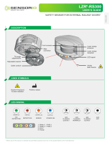
DESCRIPTION
ENGLISH
Active infrared safety sensor
for automatic doors*
Specifications are subject to changes without prior notice.
Measured in specific conditions.
User’s Guide for product version 0601 and higher
See product label for serial number
1. LED
2. Emitter
3. DIP-switch
4. Push button
5. Setup adjustment screw
6. Fixation screw
7. Receiver
8. Cable with connector
9. Front face
Technology:
Detection mode:
Detection field:
Light indicator:
Response time:
Mounting height:
Supply voltage:
Mains frequency:
Max. current consumption:
Standard output:
Max. contact voltage:
Max. contact current:
Max. switching power:
Monitoring input:
Max. contact voltage:
Voltage threshold:
Hold time:
Reflectivity:
Temperature range:
Degree of protection:
Dimensions:
Housing material:
Length of main cable:
Norm conformity:
Test body:

1
2
1
7
4
8
6
3
5
9
INSTALLATION
Use the mounting template
to cut out the opening for the
sensor.
Adapt the angle of the sensor.
MONITORING
Connect the cable and insert
the sensor into the opening.
After inserting the sensor, fix
the 2 screws firmly.
The sensor can also be installed on the surface by using
thesurface mount accessory (sold seperately).
Push the push button shortly
to launch an automatic setup.
The LED will flash RED-GREEN.
When the LED turns OFF the
sensor is correctly installed.
Fasten the front face and test
the good functioning of the
sensor.
If the LED continues flashing,
you have to adjust the sensor
further (see SETUP next page).
DETECTION
NO DETECTION
NO POWER
NO - ACTIVE NC - PASSIVE
YELLOW-BLACK
YELLOW-WHITE
RED
BLUE
BROWN
GREEN
YELLOW - COM
WHITE - NC
BLACK - NO
Unclips the front face by
inserting a screwdriver as
shown.
POWER SUPPLY
12-24 V AC/DC

2
OFF ON
1
2
3
4
4
ADDITIONAL ADJUSTMENTS (DIP-SWITCH)
AUTOMATIC MODE
ACTIVE HIGH
ACTIVE LOW
SMALL (25 CM AT 2.2 M)
FREQUENCY 1 FREQUENCY 2
MANUAL MODE
BIG (40CM AT 2.2 M)
SETUPFREQUENCYMONITORING UNCOVERED
ZONE
Do not touch the screw.
It should be positioned as
shown.
When?
- low reflectivity of background
- no background or mounting height > 3 m
- mounting height < 1.6 m
- uncovered zone > 40 cm
How?
Decrease (-) or increase (+) the uncovered zone and
check it by moving a white paper up and down
under the sensor.
Push the push button shortly
to launch an automatic setup.
When?
When 2 or more sensors are installed in
proximity to each other, it is recommended
to choose different frequencies to avoid
crosstalk.
When?
When increased door safety is required.
Relaunch a setup after changing DIP 2.
When?
When 2 or more sensors are installed in
proximity to each other, it is recommended to
choose different frequencies to avoid crosstalk.
When?
When the monitoring input mode is active low.
When?
When the monitoring input mode is active
high or when no monitoring is required.
When?
When increased immunity to disturbances is required.
Relaunch a setup after changing DIP 2.
LED flashes RED-GREEN.
OK
Switch to manual mode.
Do not move the white
paper horizontally!
(FACTORY VALUES)
After changing a DIP-switch, the orange LED flashes. A LONG push on the push button confirms the settings.

BEA SA | LIEGE Science Park | ALLÉE DES NOISETIERS 5 - 4031 ANGLEUR [BELGIUM] | T +32 4 361 65 65 | F +32 4 361 28 58 | [email protected] | WWW.BEA-SENSORS.COM
The RED LED is
ON sporadicly or
permanently.
Bad calibration.
Launch a calibration.
Bad adjustment of the unco-
vered zone.
Check if the DIP 2 is in correct position.
Launch a calibration.
The sensor is disturbed by
lamps or another sensor.
Select a different frequency for each module (DIP 3).
Launch a calibration.
The sensor does
not react, but a
calibration can be
launched.
The monitoring is activated,
but the test input is not
powered.
The monitoring mode is
wrong.
Check wiring.
- Door control with test:
Connect RED and BLUE wires to test output.
- Door control without test:
Connect BLUE to 0 V and RED to +12 V - 30 V DC.
Change position of DIP 4.
The ORANGE LED is
on permanently.
The sensor encounters a
memory problem.
Send the sensor back for a technical check-up.
The ORANGE LED
flashes quickly.
DIP-switch setting awaiting
confirmation.
Confirm the DIP-switch setting: long push on the
push button.
The ORANGE LED
flashes 1 x
every 3 seconds.
The sensor signals an
internal fault.
Cut and restore power supply.
If orange LED flashes again, replace sensor.
The ORANGE LED
flashes 2 x
every 3 seconds.
Power supply is out of limit.
Check power supply (tension, capacity).
Reduce the cable length or change cable.
The ORANGE LED
flashes 4 x
every 3 seconds.
The sensor does not receive
enough IR-energy.
Launch a new calibration.
Step out of the detection field.
Change angle of spots.
The ORANGE LED
flashes 5 x
every 3 seconds.
Calibration error.
Check mounting height.
Change position of calibration screw.
Launch a new calibration.
1
2
2
3
1
2
1
1
2
1
2
2
1
1
1
1
2
3
1
©BEA | Original instructions | 47.0177 / V2 - 01.18
TROUBLESHOOTING
Only for EC countries: According to the European Guideline 2012/19/EU for Waste Electrical and Electronic Equipment (WEEE)
PLEASE KEEP FOR FURTHER USE - DESIGNED FOR COLOUR PRINTING
Avoid reflective background
or objects in the detection
field of the sensor.
Avoid high intensity lightning
in the detection field.
Do not cover the sensor. Do not touch the optical
parts.
INSTALLATION TIPS
• The device cannot be used for purposes other than its intended use. All other uses cannot be guaranteed by the manufacturer of the sensor.
• The manufacturer of the door system is responsible for carrying out a risk assessment and installing the sensor and the door system in compliance
with applicable national and international regulations and standards on door safety.
• The manufacturer of the sensor cannot be held responsible for incorrect installations or inappropriate adjustments of the sensor.
• Only trained and qualified personnel may install and setup the sensor.
• The warranty is invalid if unauthorized repairs are made or attempted by unauthorized personnel.
BEA hereby declares that the 1SAFE is in conformity with the basic requirements and the other relevant
provisions of the directives EMC 2014/30/EU and the RoHS 2 2011/65/EU.
Notified Body for EC-type inspection: 0044 - TÜV NORD CERT GmbH, Langemarckstr. 20, D-45141 Essen
EC-type examination certificate number: 44 205 13089615
The complete declaration of conformity is available on our website.
2
1
4
5
/