©2019 TP-Link 7106508372 REV3.2.0
For technical support and other information, please visit
https://www.tp-link.com/support, or simply scan the QR code.
The products of TP-Link partly contain software code developed by third parties, including software code subject to the GNU General Public License (“GPL”). As
applicable, the terms of the GPL and any information on obtaining access to the respective GPL Code used in TP-Link products are available to you in GPL-Code-Cen-
tre under (https://www.tp-link.com/en/support/gpl/). The respective programs are distributed WITHOUT ANY WARRANTY and are subject to the copyrights of one or
more authors. For details, see the GPL Code and other terms of the GPL.
The EAP supports two configuring options:
To configure and manage EAPs singly (usually suitable for a small network with a few
EAPs), Standalone Mode is recommended. Please refer to Option 1.
To configure and manage EAPs in batch, Controller Mode is recommended. Please refer to
Option 2.
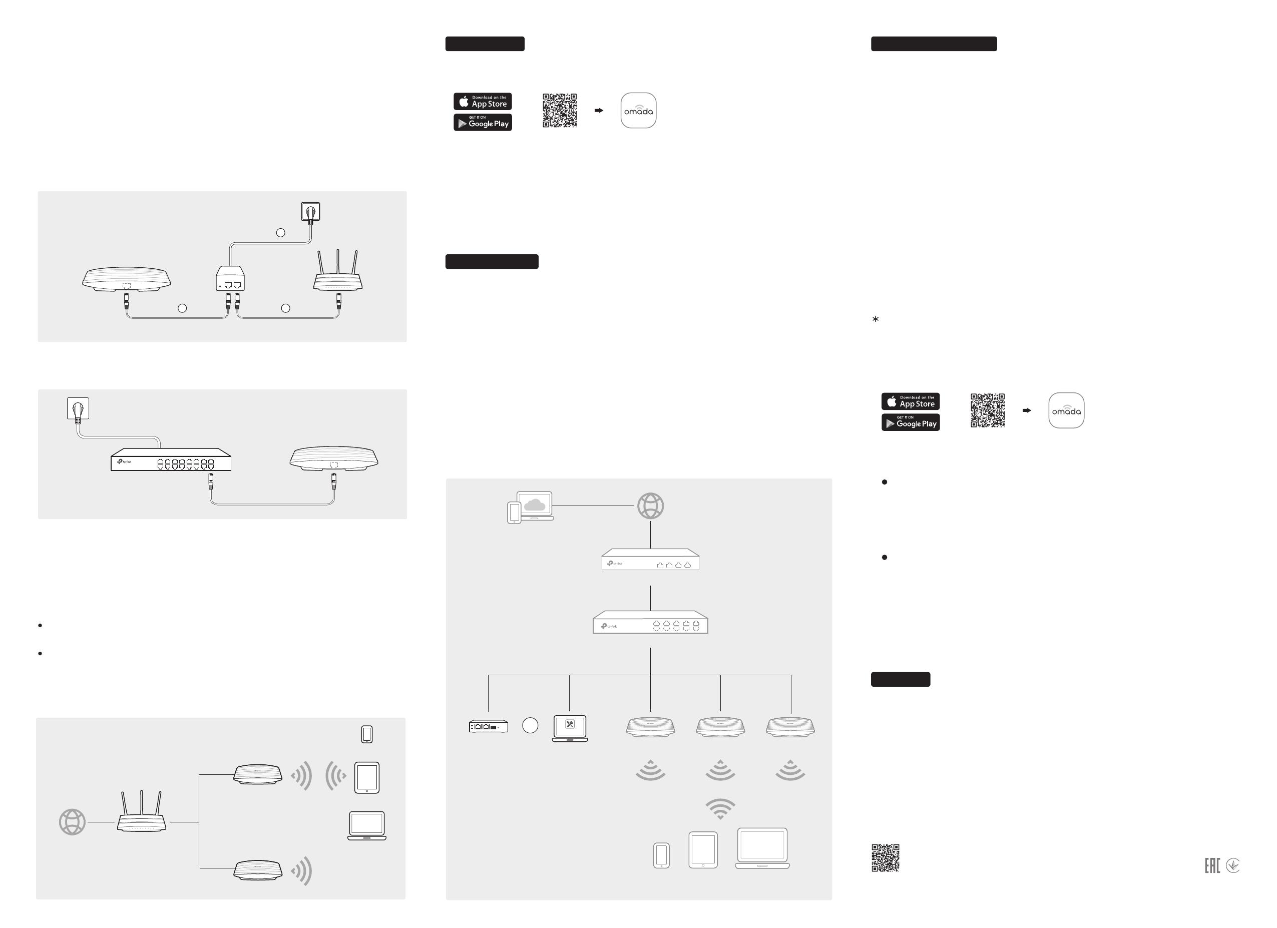
The EAP can be powered via a power adapter or a PSE device (such as a PoE switch) .
Connect an Ethernet cable from the PoE switch to the Ethernet port (ETH1 for EAP245).
Via PoE Switch
PoE Switch
Option1: Standalone Mode
A DHCP server (typically a router with DHCP function enabled) is required to assign IP
addresses to the EAPs and clients in your local network.
Via Omada App
1. Connect wirelessly by using the default SSID (format: TP-Link_2.4GHz/5GHz_XXXXXX) printed
on the label at the bottom of the product.
2. Launch a web browser and enter http://tplinkeap.net
in the address bar. Use admin for both
Username and Password to log in.
3. Set up a new Username and Password for secure management purpose. Modify the wireless
parameters and reconnect your wireless devices to the new wireless network.
To configure other EAPs, connect your device to the EAP by the coresponding default SSID and
repeat the steps listed above. You can configure some basic functions in Standalone Mode. If you
want to configure advanced functions, use Controller Mode.
1. Download the TP-Link Omada app on your mobile device. It can be downloaded from Apple
Store or Google Play:
Scan for Omada App Download Omada App
or
2. Connect your mobile device to the EAP by using the default SSID (format:
TP-Link_2.4GHz/5GHz_XXXXXX) printed on the label at the bottom of the product.
3. Open the Omada app, and wait for the EAP to appear on the Standalone APs page. Tap on the
EAP you want to congure.
The Omada app is designed to help you quickly configure the common settings. If you want to
configure advanced settings, log in to the web page of your EAP or the controller.
Via a Web Browser
Via OC200
Omada Cloud Controller (OC200), which is pre-installed with the Omada Software Controller,
is a good alternative for the Software Controller if you have no spare PC to keep running in
the network. It needs to be purchased additionally. For more details, refer to the Installation
Guide of OC200.
Via Software Controller
1. On the PC with Windows OS or Linux OS, download the Omada Controller installation file
from http://www.tp-link.com/en/download/EAP-Controller.html.
2. Run the file and follow the wizard to install the Omada Controller.
3. Launch the Omada Controller and follow the step-by-step instructions to complete the
Quick Setup. After the wizard is finished, a login screen will appear.
4. Enter the username and password you created and click Log in. Then you can further
configure the Omada Controller.
Power Supply
Software Configuration
Option2: Controller Mode
Controller Mode is applicable to configuration for mass EAPs. All EAPs can be centrally
configured and monitored via an Omada Software Controller or an Omada Cloud Controller
(OC200).
Omada Cloud Service
1. Download the TP-Link Omada app on your mobile device. It can be downloaded from Apple
Store or Google Play:
Scan for Omada App Download Omada App
or
With Omada app, you can also manage your Omada Controller at a local site and remote site.
Note that Omada software Controller needs to be kept running when using Omada app.
Local Management
For detailed configurations, please visit https://www.tp-link.com/support to download the
User Guide of EAP in the download center.
To ask questions, find answers, and communicate with TP-Link users or engineers, please
visit https://community.tp-link.com to joinTP-Link Community.
Via Power Adapter
1. Connect the Ethernet cable from the Ethernet port (ETH1 for EAP245) of the EAP device to
the provided power adapter’s PoE port.
2. Connect an Ethernet cable from your LAN to the power adapter’s LAN port.
3. Connect the power cord to the adapter’s power socket. Connect the other end of the
power cord to a standard electrical wall outlet.
(Up to 100m)
PoE Adapter
PoE LAN
1 2
3
Switch
Router
EAP EAP
Clients
OC200
Omada Controller
Omada Software Controller
running on the Management PC
Or
EAP
After installing Omada Controller, you can remotely access and configure the controller
through cloud service. Follow the steps below.
1. Enable Cloud Access on the setting page on the controller and bind a TP-Link ID to your
controller. If you have congured this in the setup wizard, skip the step.
2. Launch a web browser and enter https://omada.tplinkcloud.com in the address bar.
3. Enter your TP-Link ID and password to log in. A list of Omada Controller that has been
bound with your TP-Link ID will appear. Then you can click Launch to further congure the
controller.
Omada App
2. Launch your app and configure the controller at local a site or remote site.
Remote Management
a. Connect your mobile device to the EAP by using the default SSID (format:
TP-Link_2.4GHz/5GHz_XXXXXX) printed on the label at the bottom of the product.
b. Launch the app and go to Local Access, tap the
+ button on the upper-right corner to
add the Omada Controller. Then you can further congure the controller.
a. Make sure Cloud Access is enabled on your controller and your controller has been
bound with a TP-Link ID.
b. Launch the app and log in with your TP-Link ID. Then go to Cloud Access. A list of
Omada Controller that has been bound with your TP-Link ID will appear. Then you can
further configure the controller.
Internet
EAP
Clients
Router
EAP

