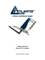
Trendnet TEW-641PC Owner's manual

Category
Access control readers
Type
Owner's manual

This manual is also suitable for

i
ii
Federal Communication Commission Interference Statement
This equipment has been tested and found to comply with the limits for a Class B digital device, pursuant to Part 15 of the FCC Rules.
These limits are designed to provide reasonable protection against harmful interference in a residential installation. This equipment
generates, uses and can radiate radio frequency energy and, if not installed and used in accordance with the instructions, may cause
harmful interference to radio communications. However, there is no guarantee that interference will not occur in a particular
installation. If this equipment does cause harmful interference to radio or television reception, which can be determined by turning
the equipment off and on, the user is encouraged to try to correct the interference by one of the following measures:
- Reorient or relocate the receiving antenna.
- Increase the separation between the equipment and receiver.
- Connect the equipment into an outlet on a circuit different from that to which the receiver is connected.
- Consult the dealer or an experienced radio/TV technician for help.
FCC Caution: Any changes or modifications not expressly approved by the party responsible for compliance could void the user's
authority to operate this equipment.
This device complies with Part 15 of the FCC Rules. Operation is subject to the following two conditions: (1) This device may not
cause harmful interference, and (2) this device must accept any interference received, including interference that may cause undesired
operation.
TEW641PC
IMPORTANT NOTE:
Radiation Exposure Statement:
This equipment complies with FCC radiation exposure limits set forth for an uncontrolled environment. End users must follow the
specific operating instructions for satisfying RF exposure compliance. To maintain compliance with FCC RF exposure compliance
requirements, please follow operation instruction as documented in this manual.
This transmitter must not be co-located or operating in conjunction with any other antenna or transmitter.
SAR compliance has been established in typical laptop computer(s) with CardBus slot, and product could be used in typical laptop
computer with CardBus slot. Other application like handheld PC or similar device has not been verified and may not compliance with
related RF exposure rule and such use shall be prohibited.
Europe – EU Declaration of Conformity
This device complies with the essential requirements of the R&TTE Directive 1999/5/EC. The following test methods have been
applied in order to prove presumption of conformity with the essential requirements of the R&TTE Directive 1999/5/EC:
EN 60 950-1: 2001 +A11: 2004
Safety of Information Technology Equipment
EN 50392: (2004-01)
Generic standard to demonstrate the compliance of electronic and electrical apparatus with the basic restrictions related to human
exposure to electromagnetic fields (0 Hz - 300 GHz)
EN 300 328 V1.7.1: (2006-10)
Electromagnetic compatibility and Radio spectrum Matters (ERM); Wideband Transmission systems; Data transmission equipment
operating in the 2,4 GHz ISM band and using spread spectrum modulation techniques; Harmonized EN covering essential
requirements under article 3.2 of the R&TTE Directive
iii
EN 301 489-1 V1.6.1: (2005-09)
Electromagnetic compatibility and Radio Spectrum Matters (ERM); ElectroMagnetic Compatibility (EMC) standard for radio
equipment and services; Part 1: Common technical requirements
EN 301 489-17 V1.2.1 (2002-08)
Electromagnetic compatibility and Radio spectrum Matters (ERM); ElectroMagnetic Compatibility (EMC) standard for radio
equipment and services; Part 17: Specific conditions for 2,4 GHz wideband transmission systems and 5 GHz high performance RLAN
equipment
This device is a 2.4 GHz wideband transmission system (transceiver), intended for use in all EU member states and EFTA countries,
except in France and Italy where restrictive use applies.
In Italy the end-user should apply for a license at the national spectrum authorities in order to obtain authorization to use the device
for setting up outdoor radio links and/or for supplying public access to telecommunications and/or network services.
This device may not be used for setting up outdoor radio links in France and in some areas the RF output power may be limited to 10
mW EIRP in the frequency range of 2454 – 2483.5 MHz. For detailed information the end-user should contact the national spectrum
authority in France.
TEW643PI
IMPORTANT NOTE:
FCC Radiation Exposure Statement:
This equipment complies with FCC radiation exposure limits set forth for an uncontrolled environment. This equipment should be
installed and operated with minimum distance 20cm between the radiator & your body.
This transmitter must not be co-located or operating in conjunction with any other antenna or transmitter.
The availability of some specific channels and/or operational frequency bands are country dependent and are firmware programmed at
the factory to match the intended destination. The firmware setting is not accessible by the end user.
Europe – EU Declaration of Conformity
This device complies with the essential requirements of the R&TTE Directive 1999/5/EC. The following test methods have been
applied in order to prove presumption of conformity with the essential requirements of the R&TTE Directive 1999/5/EC:
EN 60 950-1: 2001 +A11: 2004
Safety of Information Technology Equipment
EN 50392: (2004-01)
Generic standard to demonstrate the compliance of electronic and electrical apparatus with the basic restrictions related to human
exposure to electromagnetic fields (0 Hz - 300 GHz)
EN 300 328 V1.7.1: (2006-10)
Electromagnetic compatibility and Radio spectrum Matters (ERM); Wideband Transmission systems; Data transmission equipment
operating in the 2,4 GHz ISM band and using spread spectrum modulation techniques; Harmonized EN covering essential
requirements under article 3.2 of the R&TTE Directive
EN 301 489-1 V1.6.1: (2005-09)
Electromagnetic compatibility and Radio Spectrum Matters (ERM); ElectroMagnetic Compatibility (EMC) standard for radio
equipment and services; Part 1: Common technical requirements
EN 301 489-17 V1.2.1 (2002-08)
Electromagnetic compatibility and Radio spectrum Matters (ERM); ElectroMagnetic Compatibility (EMC) standard for radio
equipment and services; Part 17: Specific conditions for 2,4 GHz wideband transmission systems and 5 GHz high performance RLAN
equipment
iv
This device is a 2.4 GHz wideband transmission system (transceiver), intended for use in all EU member states and EFTA countries,
except in France and Italy where restrictive use applies.
In Italy the end-user should apply for a license at the national spectrum authorities in order to obtain authorization to use the device
for setting up outdoor radio links and/or for supplying public access to telecommunications and/or network services.
This device may not be used for setting up outdoor radio links in France and in some areas the RF output power may be limited to 10
mW EIRP in the frequency range of 2454 – 2483.5 MHz. For detailed information the end-user should contact the national spectrum
authority in France.
v
TABLE OF CONTENT
Introduction ................................................................................................ 1
Overview of this User’s Guide ............................................................................... 1
Unpacking and Setup .................................................................................. 2
Unpacking .............................................................................................................. 2
Setup ....................................................................................................................... 2
IDentifying external components ............................................................... 3
LED ........................................................................................................................ 3
Check the installation ............................................................................................. 3
Software Installation ................................................................................... 4
Windows Based Utility Installation ........................................................................ 4
Wireless Utility Setting .............................................................................. 6
Link Information .................................................................................................... 6
Configuration .......................................................................................................... 7
Site Survey ........................................................................................................... 10
Profile ................................................................................................................... 11
WPS ...................................................................................................................... 12
About .................................................................................................................... 16
Technical Specifications ........................................................................... 17
1
INTRODUCTION
Congratulations on your purchase of this 802.11n Wireless LAN Adapter
This manual contains detailed instructions regarding the operation of this product.
Please keep this manual for future reference.
With the 802.11n Wireless LAN Adapter, a desktop or laptop computer can
communicate with another computer wirelessly. An easy-to-use utility is bundled
with the 802.11n Wireless LAN Adapter for configuration, monitoring, and
diagnostic purposes.
The 802.11n Wireless LAN Adapter can provides wireless speed wireless speed up
300Mbps RX PHY Rate,150Mbps TX PHY Rate.
The 802.11n Wireless LAN Adapter provides users with access to real-time
information anywhere in their organization. The mobility of the 802.11n Wireless
LAN PCI Adapter provides productivity and service, which are not available under
wired networks. The 802.11n Wireless LAN CardBus Adapter can easily adapt
from peer-to-peer networks, suitable for a small number of users, to full
infrastructure networks of thousands of users that allow roaming around a broad
area.
Overview of this User’s Guide
Introduction. Describes the 802.11n Wireless LAN Adapter and its features.
Unpacking and Setup. Helps you get started with the basic installation of the
802.11n Wireless LAN Adapter.
Hardware Installation. Describes the LED indicator on the Adapter.
Software Installation. Describes how to setup the driver and the utility setting.
Technical Specifications. Lists the technical (general, physical and environmental)
specifications of the 802.11n Wireless LAN Adapter.
2
UNPACKING AND SETUP
This section provides unpacking and setup information for the Wireless N CardBus
Adapter.
Unpacking
The box should contain the following items:
TEW-641PC PC Card or TEW-643PI PCI Adapter
CD-ROM (Utility/Driver and User’s Guide)
Multi-Language Quick Installation Guide
If any item is found missing or damaged, please contact your local reseller for
replacement.
Setup
Before installation, check the following:
Make sure your computer is running at least a 300MHz or above processor with
256MB RAM or above
z Visually inspect the PCI Adapter and make sure that it is fully plugged in to the
PCI slot. (TEW-641PC)
z Visually inspect the CardBus Adapter and make sure that it is fully plugged in
to the PCMCIAI slot. (TEW-643PI)
The operating system on your computer must be the following: Windows 7,
Vista, XP (Service Pack 2) or 2000 (Service Pack 4)
A 802.11n or 802.11b/g access point.
Make sure the environment has minimal interference and obstructions.
3
IDENTIFYING EXTERNAL COMPONENTS
LED
Link
The Link LED indicator lighted green when the 802.11n Wireless LAN Adapter is
connected to wireless network successfully.
ACT (Activity)
The ACT LED indicator blinking green when the 802.11n Wireless LAN Adapter
is transmitting or receiving data.
Check the installation
The LEDs of the Wireless LAN Adapter are clearly visible and the status of the
network link can be seen instantly:
TEW-641PC
1. Once the device is plugged to the station’s PCMCIA slot, the LED of the
Wireless LAN Adapter will light up indicating a normal status.
2. When the device plugged to the station’s PCMCIA slot and the driver was
installed, the ACT will start alternate blinking, it means that the device is starting
to scan the wireless devices near the Wireless LAN Adapter.
3. While the Wireless LAN Adapter linked up and transmitting data to the Access
Point or to other Wireless LAN station, the Link LED will lighted green.
TEW-643PI
1. Once the device is plugged to the station’s PCI slot, the LED of the Wireless
LAN Adapter will light up indicating a normal status.
2. When the device plugged to the station’s PCI slot and the driver was installed,
the ACT will start alternate blinking, it means that the device is starting to scan
the wireless devices near the Wireless LAN Adapter.
3. While the Wireless LAN Adapter linked up and transmitting data to the Access
Point or to other Wireless LAN station, the Link LED will lighted green.
4
SOFTWARE INSTALLATION
This section describes how to install the driver and utility for the 802.11n Wireless
LAN Adapter.
Windows Based Utility Installation
1) Insert the Utility and Driver CD-ROM into your computer’s CD-ROM Drive and
then click Install Utility.
2) Follow the InstallShield Wizard Instructions
5
3) Click Finish to restart the computer.
4) Plug the TEW-641PC into an available CardBus slot or TEW-643PI in to an
available PCI slot on your computer. (Please follow the Quick Installation
Guide to install the driver)
6
WIRELESS UTILITY SETTING
The user can configure the wireless settings using the Wireless Adapter
Configuration Utility. Double-click the utility icon that appears in the taskbar.
The Wireless Adapter Configuration Utility is divided into six sections: Link Info,
Configuration, Site Survey, Profile, WPS and About.
Link Information
This is the default screen after launching the Utility program.
Status: Shows the associated BSSID, which can be used to identify the wireless
access point.
SSID: Shows the current SSID, which must be the same on the wireless client and
AP in order for communication to be established.
Frequency: Shows the current frequency used for the wireless network.
Wireless Mode: Shows the current wireless mode used for wireless communication.
Encryption: Shows the current encryption mode used on the wireless network.
TxRate: Shows the current data rate used for transmitting.
7
Channel: Shows the current channel for communication.
Link Quality: Shows the link quality of the Wireless N CardBus Adapter with the
Access Point when operating under Infrastructure mode.
Signal Strength: Shows the wireless signal strength of the connection between the
Wireless N CardBus Adapter with the Access Point.
Data Rate:
Shows the statistics of data transfer, and the calculation is based on the
number of packets transmitted and received.
Configuration
This screen is where you set the basic wireless settings for the Wireless N CardBus
Adapter.
Profile Name: Shows the Profile Name.
SSID: Service Set Identifier, which is a unique name shared among all clients in a
wireless network. The SSID must be identical for each client in the wireless
network.
Wireless Mode: There are two modes available for selection
Infrastructure – to establish wireless communication with the LAN and other
wireless clients through the use of Access Points.
8
Ad-Hoc – to establish point-to-point wireless communication directly with
other wireless client devices.
Authtication: The following options are available: Open System, Shared Key,
WPA-PSK, WPA2-PSK, WPA EAP-TLS, WPA2 EPA-TLS. Select Open System,
Shared Key for WEP data encryption feature.
Open or Shared Key
Open System and Shared Key require the user to set a WEP key to exchange
data with other wireless clients that have the same WEP key.
z Default Key: select one of the 4 keys to use.
z Network Key: choose the encryption way, either in HEX or ASCII formats,
and enter the password in the blank space.
z Key Length: select 64 or 128 bits as the length of the keys
Key Format: HEX or ASCII
WPA-PSK / WPA2-PSK
If using the WPA-PSK/WPA2-PSK authentication method, please select the
Encryption type for TKIP or AES then enter the Passphrase key. The minimum
length is 8 characters.
9
WPA EAP-TLS
If using the WPA/WPA2 EAP-TLS authentication method, please select the
Encryption type for TKIP or AES then select the WPA/WPA2 Certificate from
drop down list.
10
Site Survey
This screen allows the user to scan for available wireless networks (wireless clients
and Access Points). It also allows the user to establish wireless communications
with an available wireless network.
Available Network – displays the wireless networks (wireless clients and access
points) that are within range.
Select any one of the wireless networks by double-clicking on it or clicking on the
Connect” button.
Click the “Refresh” button to scan for available networks.
11
Profile
Profile – The user can create and manage the created profiles for home, work or
public areas. By double-clicking on one of the created profile, the setting will adjust
to the specific setting such as SSID, channel, and encryption as saved by that
particular profile.
Add: Adds a profile. The following screen will appear. The user can enter the
necessary information required for accessing Access Points or Wireless Router
Remove: Deletes the selected profile
Edit: Edit an exist profile. The screen will back to profile. Edit the SSID and select
the Wireless Mode, Authentication and Encryption then click Apply to save the
profile. When the Profile name was changed, a new profile will be added in the list.
Connect: Selected a profile from list then click the Connect to connecting to the
wireless network with the profile setting.
12
WPS
Wi-Fi Protected Setup (WPS) is an optional certification program from the Wi-Fi
Alliance that is designed to ease the task of setting up and configuring security on a
wireless network. There are two methods used in the WPS as below instruction.
Push the button on my access point
Using the WPS configuration with the “Push the button on my access point”
method, the configuration steps as below:
1) Selected the “Push the button on my access point”.
2) Push the WPS configuration button on your wireless access point or router.
3) Click the Next button start the WPS configuration.
13
4) If the WPS configuration was successful, the follow window will appear.
5) If the WPS configuration failed, the follow window will appear.
14
Enter a PIN into my access point
Using the WPS configuration with the “Enter a PIN into my access point” method,
the configuration steps as below:
1) Selected the “Enter a PIN into my access point”, the PIN will be show on the
button of the windows.
2) Enter the PIN code into the WPS “Clint PIN number” of you wireless access
point or router then click the Start PIN button, the wireless access point or
router will start the WPS configuration process.
3) Selected a wireless access point or router which one will be connecting then
click the Next button start the WPS configuration. If the “Automatically select
the network” was checked, the setup step will be skip.
15
4) If the WPS configuration was successful, the follow window will appear.
5) If the WPS configuration failed, the follow window will appear.
  • Page 1 1
  • Page 2 2
  • Page 3 3
  • Page 4 4
  • Page 5 5
  • Page 6 6
  • Page 7 7
  • Page 8 8
  • Page 9 9
  • Page 10 10
  • Page 11 11
  • Page 12 12
  • Page 13 13
  • Page 14 14
  • Page 15 15
  • Page 16 16
  • Page 17 17
  • Page 18 18
  • Page 19 19
  • Page 20 20
  • Page 21 21
  • Page 22 22
  • Page 23 23
  • Page 24 24
  • Page 25 25
  • Page 26 26

Trendnet TEW-641PC Owner's manual

Category
Access control readers
Type
Owner's manual
This manual is also suitable for

Ask a question and I''ll find the answer in the document

Finding information in a document is now easier with AI