Page is loading ...

Precision 5720 All-in-One
Owner’s Manual
Regulatory Model: W13C
Regulatory Type: W13C001

Notes, cautions, and warnings
NOTE: A NOTE indicates important information that helps you make better use of your product.
CAUTION: A CAUTION indicates either potential damage to hardware or loss of data and tells you how to avoid the problem.
WARNING: A WARNING indicates a potential for property damage, personal injury, or death.
© 2017 Dell Inc. or its subsidiaries. All rights reserved. Dell, EMC, and other trademarks are trademarks of Dell Inc. or its subsidiaries. Other trademarks
may be trademarks of their respective owners.
2017 - 04
Rev. A00

Contents
1 Working on your computer............................................................................................................................. 8
Safety instructions............................................................................................................................................................. 8
Before working inside your computer..............................................................................................................................8
Turning o your computer................................................................................................................................................ 9
Turning o your computer — Windows 10...............................................................................................................9
Turning o your computer — Windows 7................................................................................................................ 9
Safety precautions............................................................................................................................................................. 9
Standby power............................................................................................................................................................. 9
Bonding .......................................................................................................................................................................10
Electrostatic discharge (ESD) protection......................................................................................................................10
ESD eld service kit ........................................................................................................................................................ 10
Components of an ESD eld service kit.................................................................................................................. 10
ESD protection summary ...........................................................................................................................................11
Transporting sensitive components................................................................................................................................ 11
Lifting equipment ........................................................................................................................................................11
After working inside your computer............................................................................................................................... 12
2 Removing and installing components............................................................................................................13
USB dongle-bay cover..................................................................................................................................................... 13
Removing USB dongle-bay cover.............................................................................................................................13
Installing dongle-bay cover........................................................................................................................................ 13
Back cover.........................................................................................................................................................................14
Removing back cover ................................................................................................................................................14
Installing back cover................................................................................................................................................... 14
Memory module................................................................................................................................................................15
Removing memory module........................................................................................................................................15
Installing memory module.......................................................................................................................................... 16
Hard drive.......................................................................................................................................................................... 16
Removing HDD/SSD..................................................................................................................................................16
Installing HDD/SSD.................................................................................................................................................... 18
System board shield......................................................................................................................................................... 18
Removing system-board shield................................................................................................................................. 18
Installing system-board shield................................................................................................................................... 19
M.2 PCIe SSD .................................................................................................................................................................. 19
Removing M.2 PCIe SSD...........................................................................................................................................19
Installing PCIe SSD.................................................................................................................................................... 20
Memory fan...................................................................................................................................................................... 20
Removing memory fan.............................................................................................................................................. 20
Installing memory fan................................................................................................................................................. 21
Heat sink........................................................................................................................................................................... 22
Removing processor heatsink for systems with discrete graphics...................................................................... 22
Removing heatsink for computers with integrated graphics................................................................................22
Installing processor heatsink.....................................................................................................................................23
Contents
3

Processor.......................................................................................................................................................................... 23
Removing processor.................................................................................................................................................. 23
Installing processor.................................................................................................................................................... 24
Coin cell battery............................................................................................................................................................... 25
Removing coin-cell battery.......................................................................................................................................25
Installing coin-cell battery......................................................................................................................................... 25
WLAN card....................................................................................................................................................................... 26
Removing wireless card.............................................................................................................................................26
Installing the wireless card........................................................................................................................................ 27
Stand..................................................................................................................................................................................27
Removing stand..........................................................................................................................................................27
Installing stand............................................................................................................................................................28
System fan........................................................................................................................................................................28
Removing system fan................................................................................................................................................ 28
Installing system fan.................................................................................................................................................. 30
Power supply unit............................................................................................................................................................ 30
Removing power supply unit.................................................................................................................................... 30
Installing power supply unit.......................................................................................................................................32
Inner frame........................................................................................................................................................................33
Removing inner frame............................................................................................................................................... 33
Installing inner frame..................................................................................................................................................34
Built-in self test button....................................................................................................................................................34
Removing built-in self test button............................................................................................................................34
Installing the built-in self test button board............................................................................................................35
Microphone.......................................................................................................................................................................36
Removing microphone...............................................................................................................................................36
Installing microphone................................................................................................................................................. 37
I/O panel........................................................................................................................................................................... 38
Removing I/O panel...................................................................................................................................................38
Installing I/O panel..................................................................................................................................................... 39
USB-dongle port..............................................................................................................................................................40
Removing USB-dongle port......................................................................................................................................40
Installing USB-dongle port.........................................................................................................................................41
Diagnostic light and button board..................................................................................................................................42
Removing the diagnostic light and button board ..................................................................................................42
Installing diagnostic light and button board............................................................................................................ 44
Drive cage......................................................................................................................................................................... 44
Removing HDD/SSD cage........................................................................................................................................44
Installing HDD/SSD cage.......................................................................................................................................... 47
Converter board............................................................................................................................................................... 47
Removing converter board....................................................................................................................................... 47
Installing converter board..........................................................................................................................................49
Speaker............................................................................................................................................................................. 50
Removing speakers....................................................................................................................................................50
Installing speaker.........................................................................................................................................................51
Power button board.........................................................................................................................................................52
Removing power-button board................................................................................................................................ 52
4
Contents

Installing power button board...................................................................................................................................53
Media card reader............................................................................................................................................................53
Removing media-card reader................................................................................................................................... 53
Installing media card reader...................................................................................................................................... 54
Camera..............................................................................................................................................................................54
Removing camera...................................................................................................................................................... 54
Installing camera........................................................................................................................................................ 55
System board................................................................................................................................................................... 56
Removing system board............................................................................................................................................56
Installing system board.............................................................................................................................................. 59
System board callouts .............................................................................................................................................. 60
Display assembly...............................................................................................................................................................61
Removing display assembly....................................................................................................................................... 61
Installing display assembly.........................................................................................................................................62
Middle frame.....................................................................................................................................................................63
Removing middle frame............................................................................................................................................ 63
Installing middle frame...............................................................................................................................................65
Speaker bezel................................................................................................................................................................... 66
Removing speaker bezel........................................................................................................................................... 66
Installing speaker bezel..............................................................................................................................................67
Display panel..................................................................................................................................................................... 67
Removing display panel............................................................................................................................................. 67
Installing display panel............................................................................................................................................... 68
3 Technology and components........................................................................................................................73
Processors........................................................................................................................................................................ 73
Skylake processors.....................................................................................................................................................73
Kaby Lake ................................................................................................................................................................... 74
Identifying processors in Windows 7....................................................................................................................... 75
Identifying processors in Windows 10......................................................................................................................75
Verifying the processor usage in Task Manager (Windows 7 and Windows 10) ...............................................75
Verifying the processor usage in Resource Monitor (Windows 7 and Windows 10) ........................................ 75
Chipsets............................................................................................................................................................................ 75
Downloading the chipset driver................................................................................................................................75
Identifying chipset in Device Manager on Windows 7...........................................................................................76
Identifying the chipset in Device Manager on Windows 10.................................................................................. 76
Display options..................................................................................................................................................................76
Identifying the display adapters in Windows 7........................................................................................................76
Identifying the display adapters in Windows 10......................................................................................................76
Graphics options.........................................................................................................................................................76
Changing the screen resolution (Windows 7 and Windows 10)...........................................................................76
Adjusting brightness in Windows 7.......................................................................................................................... 77
Adjusting brightness in Windows 10.........................................................................................................................77
Storage options................................................................................................................................................................ 77
Hard drive options............................................................................................................................................................ 77
Identifying the hard drive in Windows 7.................................................................................................................. 77
Identifying the hard drive in Windows 10.................................................................................................................77
Contents
5

Identifying the hard drive in BIOS setup program..................................................................................................77
USB features.....................................................................................................................................................................78
USB 3.0 (SuperSpeed USB).....................................................................................................................................78
Speed...........................................................................................................................................................................78
Applications.................................................................................................................................................................79
Compatibility............................................................................................................................................................... 79
Downloading the USB 3.0 driver..............................................................................................................................80
HDMI................................................................................................................................................................................. 80
Connecting to external display devices...................................................................................................................80
Wi-Fi.................................................................................................................................................................................. 80
Turning Wi-Fi on or o.............................................................................................................................................. 80
Conguring Wi-Fi........................................................................................................................................................81
Downloading the Wi-Fi driver....................................................................................................................................81
Camera...............................................................................................................................................................................81
Identifying the webcam in device manager.............................................................................................................81
Starting the camera application............................................................................................................................... 82
Memory features..............................................................................................................................................................82
Verifying system memory in Windows 10 and Windows 7 ...................................................................................82
Verifying system memory in setup...........................................................................................................................82
DDR4........................................................................................................................................................................... 83
Testing memory using ePSA.....................................................................................................................................84
Media-card reader........................................................................................................................................................... 84
Downloading the media-card reader driver............................................................................................................ 84
Realtek HD audio drivers.................................................................................................................................................84
Downloading the audio driver...................................................................................................................................85
Operating System............................................................................................................................................................ 85
Service tag location.........................................................................................................................................................85
4 System setup............................................................................................................................................... 87
BIOS Overview................................................................................................................................................................. 87
Boot menu...................................................................................................................................................................87
Navigation Keys.......................................................................................................................................................... 87
Updating the BIOS in Windows ...............................................................................................................................88
System setup options......................................................................................................................................................88
5 Software......................................................................................................................................................96
Operating system congurations...................................................................................................................................96
Downloading graphic drivers.......................................................................................................................................... 96
Intel Virtual Button driver................................................................................................................................................96
Intel Wi-Fi and Bluetooth drivers....................................................................................................................................98
Intel Trusted Execution Engine Interface...................................................................................................................... 98
Intel Serial IO Driver......................................................................................................................................................... 99
Intel chipset drivers.........................................................................................................................................................101
Graphics drivers...............................................................................................................................................................101
Trusted Platform Module (TPM) .................................................................................................................................102
Overview................................................................................................................................................................... 102
TPM 2.0 - Installing Dell TPM Update utility for Windows/DOS....................................................................... 102
6
Contents

6 Troubleshooting..........................................................................................................................................104
System diagnostic lights................................................................................................................................................104
Dell Enhanced Pre-Boot System Assessment (ePSA) diagnostic 3.0..................................................................... 105
LCD built in self test (BIST).......................................................................................................................................... 105
Initiating BIST ...........................................................................................................................................................107
7 Technical specications..............................................................................................................................108
System specications.................................................................................................................................................... 108
Memory specications...................................................................................................................................................108
Video specications....................................................................................................................................................... 109
Audio specications....................................................................................................................................................... 109
Communication specications.......................................................................................................................................110
Connectors.......................................................................................................................................................................110
Display specications......................................................................................................................................................110
Storage specications.................................................................................................................................................... 110
Port and connector specications................................................................................................................................ 110
Power specications........................................................................................................................................................111
Camera specications..................................................................................................................................................... 111
Stand specications.........................................................................................................................................................111
Physical specications....................................................................................................................................................112
Environmental specications......................................................................................................................................... 112
8 Contacting Dell........................................................................................................................................... 113
Contents
7

Working on your computer
Safety instructions
Use the following safety guidelines to protect your computer from potential damage and to ensure your personal safety. Unless otherwise
noted, each procedure included in this document assumes that the following conditions exist:
• You have read the safety information that shipped with your computer.
• A component can be replaced or, if purchased separately, installed by performing the removal procedure in reverse order.
WARNING: Disconnect all power sources before opening the computer cover or panels. After you nish working inside the
computer, replace all covers, panels, and screws before connecting to the power source.
WARNING: Before working inside your computer, read the safety information that shipped with your computer. For additional
safety best practices information, see the Regulatory Compliance Homepage at www.Dell.com/regulatory_compliance
CAUTION: Many repairs may only be done by a certied service technician. You should only perform troubleshooting and simple
repairs as authorized in your product documentation, or as directed by the online or telephone service and support team. Damage
due to servicing that is not authorized by Dell is not covered by your warranty. Read and follow the safety instructions that came
with the product.
CAUTION: To avoid electrostatic discharge, ground yourself by using a wrist grounding strap or by periodically touching an
unpainted metal surface at the same time as touching a connector on the back of the computer.
CAUTION: Handle components and cards with care. Do not touch the components or contacts on a card. Hold a card by its
edges or by its metal mounting bracket. Hold a component such as a processor by its edges, not by its pins.
CAUTION: When you disconnect a cable, pull on its connector or on its pull-tab, not on the cable itself. Some cables have
connectors with locking tabs; if you are disconnecting this type of cable, press in on the locking tabs before you disconnect the
cable. As you pull connectors apart, keep them evenly aligned to avoid bending any connector pins. Also, before you connect a
cable, ensure that both connectors are correctly oriented and aligned.
NOTE: The color of your computer and certain components may appear dierently than shown in this document.
Before working inside your computer
To avoid damaging your computer, perform the following steps before you begin working inside the computer.
1 Ensure that you follow the Safety instructions.
2 Ensure that your work surface is at and clean to prevent the computer cover from being scratched.
3 Turn o your computer.
CAUTION
: To disconnect a network cable, rst unplug the cable from your computer and then unplug the cable from
the network device.
4 Disconnect all network cables from the computer.
5 Disconnect your computer and all attached devices from their electrical outlets.
6 Press and hold the power button while the computer is unplugged to ground the system board.
7 Remove the cover.
CAUTION
: Before touching anything inside your computer, ground yourself by using a wrist grounding strap or by
periodically touching an unpainted metal surface at the same time as touching a connector on the back of the computer.
1
8 Working on your computer

Turning o your computer
Turning o your computer — Windows 10
CAUTION: To avoid losing data, save and close all open les and exit all open programs before you turn o your
computer.
1 Click or tap .
2
Click or tap and then click or tap Shut down.
NOTE: Ensure that the computer and all attached devices are turned o. If your computer and attached devices did not
automatically turn o when you shut down your operating system, press and hold the power button for about 6 seconds
to turn them o.
Turning o your computer — Windows 7
CAUTION: To avoid losing data, save and close all open les and exit all open programs before you turn o your
computer.
1 Click Start.
2 Click Shut Down.
NOTE
: Ensure that the computer and all attached devices are turned o. If your computer and attached devices did not
automatically turn o when you shut down your operating system, press and hold the power button for about 6 seconds
to turn them o.
Safety precautions
The safety precautions chapter details the primary steps to be taken before performing any disassembly instructions.
Observe the following safety precautions before you perform any installation or break/x procedures involving disassembly or reassembly:
• Turn o the system and all attached peripherals.
• Disconnect the system and all attached peripherals from AC power.
• Disconnect all network cables, telephone, and telecommunications lines from the system.
• Use an ESD eld service kit when working inside any desktop to avoid electrostatic discharge (ESD) damage.
• After removing any system component, carefully place the removed component on an anti-static mat.
• Wear shoes with nonconductive rubber soles to reduce the chance of getting electrocuted.
Standby power
Dell products with standby power must be unplugged before you open the case. Systems that incorporate standby power are essentially
powered while turned o. The internal power enables the system to be remotely turned on (wake on LAN) and suspended into a sleep
mode and has other advanced power management features.
After unplugging the system and before removing components, wait approximately 30 to 45 seconds to allow the charge to drain from the
circuits. Remove the battery from portable desktops.
Working on your computer
9

Bonding
Bonding is a method for connecting two or more grounding conductors to the same electrical potential. This is done through the use of a
eld service electrostatic discharge (ESD) kit. When connecting a bonding wire, ensure that it is connected to bare metal and never to a
painted or nonmetal surface. The wrist strap should be secure and in full contact with your skin, and ensure that you remove all jewelry
such as watches, bracelets, or rings prior to bonding yourself and the equipment.
Electrostatic discharge (ESD) protection
ESD is a major concern when you handle electronic components, especially sensitive components such as expansion cards, processors,
memory DIMMs, and system boards. Very slight charges can damage circuits in ways that may not be obvious, such as intermittent
problems or a shortened product life span. As the industry pushes for lower power requirements and increased density, ESD protection is an
increasing concern.
Due to the increased density of semiconductors used in recent Dell products, the sensitivity to static damage is now higher than in previous
Dell products. For this reason, some previously approved methods of handling parts are no longer applicable.
Two recognized types of ESD damage are catastrophic and intermittent failures.
• Catastrophic – Catastrophic failures represent approximately 20 percent of ESD-related failures. The damage causes an immediate and
complete loss of device functionality. An example of catastrophic failure is a memory DIMM that has received a static shock and
immediately generates a "No POST/No Video" symptom with a beep code emitted for missing or nonfunctional memory.
• Intermittent – Intermittent failures represent approximately 80 percent of ESD-related failures. The high rate of intermittent failures
means that most of the time when damage occurs, it is not immediately recognizable. The DIMM receives a static shock, but the
tracing is merely weakened and does not immediately produce outward symptoms related to the damage. The weakened trace may
take weeks or months to melt, and in the meantime may cause degradation of memory integrity, intermittent memory errors, etc.
The more dicult type of damage to recognize and troubleshoot is the intermittent (also called latent or "walking wounded") failure.
Perform the following steps to prevent ESD damage:
• Use a wired ESD wrist strap that is properly grounded. The use of wireless anti-static straps in no longer allowed; they do not provide
adequate protection. Touching the chassis before handling parts does not ensure adequate ESD protection on parts with increased
sensitivity to ESD damage.
• Handle all static-sensitive components in a static-safe area. If possible, use anti-static oor pads and workbench pads.
• When unpacking a static-sensitive component from its shipping carton, do not remove the component from the anti-static packing
material until you are ready to install the component. Before unwrapping the anti-static packaging, be sure ensure that you discharge
static electricity from your body.
• Before transporting a static-sensitive component, place it in an anti-static container or packaging.
ESD eld service kit
The unmonitored Field Service kit is the most commonly used service kit. Each Field Service kit includes three main components: anti-static
mat, wrist strap, and bonding wire.
Components of an ESD eld service kit
The components of an ESD eld service kit are:
• Anti-Static Mat – The anti-static mat is dissipative and parts can be placed on it during service procedures. When using an anti-static
mat, your wrist strap should be snug and the bonding wire should be connected to the mat and to any bare metal on the system being
worked on. Once deployed properly, service parts can be removed from the ESD bag and placed directly on the mat. ESD-sensitive
items are safe in your hand, on the ESD mat, in the system, or inside a bag.
• Wrist Strap and Bonding Wire – The wrist strap and bonding wire can be either directly connected between your wrist and bare metal
on the hardware if the ESD mat is not required, or connected to the anti-static mat to protect hardware that is temporarily placed on
the mat. The physical connection of the wrist strap and bonding wire between your skin, the ESD mat, and the hardware is known as
bonding. Use only Field Service kits with a wrist strap, mat, and bonding wire. Never use wireless wrist straps. Always be aware that the
10
Working on your computer

internal wires of a wrist strap are prone to damage from normal wear and tear, and must be checked regularly with a wrist strap tester
in order to avoid accidental ESD hardware damage. It is recommended to test the wrist strap and bonding wire at least once per week.
• ESD Wrist Strap Tester – The wires inside of an ESD strap are prone to damage over time. When using an unmonitored kit, it is a best
practice to regularly test the strap prior to each service call, and at a minimum, test once per week. A wrist strap tester is the best
method for doing this test. If you do not have your own wrist strap tester, check with your regional oce to nd out if they have one.
To perform the test, plug the wrist-strap's bonding-wire into the tester while it is strapped to your wrist and push the button to test. A
green LED is lit if the test is successful; a red LED is lit and an alarm sounds if the test fails.
• Insulator Elements – It is critical to keep ESD sensitive devices, such as plastic heat sink casings, away from internal parts that are
insulators and often highly charged.
• Working Environment – Before deploying the ESD Field Service kit, assess the situation at the customer location. For example,
deploying the kit for a server environment is dierent than for a desktop or portable environment. Servers are typically installed in a rack
within a data center; desktops or portables are typically placed on oce desks or cubicles. Always look for a large open at work area
that is free of clutter and large enough to deploy the ESD kit with additional space to accommodate the type of system that is being
repaired. The workspace should also be free of insulators that can cause an ESD event. On the work area, insulators such as Styrofoam
and other plastics should always be moved at least 12 inches or 30 centimeters away from sensitive parts before physically handling any
hardware components
• ESD Packaging – All ESD-sensitive devices must be shipped and received in static-safe packaging. Metal, static-shielded bags are
preferred. However, you should always return the damaged part using the same ESD bag and packaging that the new part arrived in.
The ESD bag should be folded over and taped shut and all the same foam packing material should be used in the original box that the
new part arrived in. ESD-sensitive devices should be removed from packaging only at an ESD-protected work surface, and parts should
never be placed on top of the ESD bag because only the inside of the bag is shielded. Always place parts in your hand, on the ESD mat,
in the system, or inside an anti-static bag.
• Transporting Sensitive Components – When transporting ESD sensitive components such as replacement parts or parts to be
returned to Dell, it is critical to place these parts in anti-static bags for safe transport.
ESD protection summary
It is recommended that all eld service technicians use the traditional wired ESD grounding wrist strap and protective anti-static mat at all
times when servicing Dell products. In addition, it is critical that technicians keep sensitive parts separate from all insulator parts while
performing service and that they use anti-static bags for transporting sensitive components.
Transporting sensitive components
When transporting ESD sensitive components such as replacement parts or parts to be returned to Dell, it is critical to place these parts in
anti-static bags for safe transport.
Lifting equipment
Adhere to the following guidelines when lifting heavy weight equipment:
CAUTION
: Do not lift greater than 50 pounds. Always obtain additional resources or use a mechanical lifting device.
1 Get a rm balanced footing. Keep your feet apart for a stable base, and point your toes out.
2 Tighten stomach muscles. Abdominal muscles support your spine when you lift, osetting the force of the load.
3 Lift with your legs, not your back.
4 Keep the load close. The closer it is to your spine, the less force it exerts on your back.
5 Keep your back upright, whether lifting or setting down the load. Do not add the weight of your body to the load. Avoid twisting your
body and back.
6 Follow the same techniques in reverse to set the load down.
Working on your computer
11

After working inside your computer
After you complete any replacement procedure, ensure that you connect any external devices, cards, and cables before turning on your
computer.
1 Replace the cover.
CAUTION: To connect a network cable, rst plug the cable into the network device and then plug it into the
computer.
2 Connect any telephone or network cables to your computer.
3 Connect your computer and all attached devices to their electrical outlets.
4 Turn on your computer.
5 If required, verify that the computer works correctly by running ePSA diagnostics.
12 Working on your computer
Removing and installing components
This section provides detailed information on how to remove or install the components from your computer.
USB dongle-bay cover
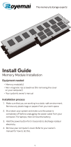
Removing USB dongle-bay cover
CAUTION: Place the computer on a at, soft and clean surface to avoid scratches on the
display.
1 Follow the procedure in Before working inside your computer
2 Place the computer face down.
3 Press and pull the USB dongle-bay cover out of your computer.
Installing dongle-bay cover
1 Align the tabs on the USB dongle-bay cover into the slots on the back cover and snap the USB dongle-bay cover into place.
2 Follow the procedure in After working inside your computer.
2
Removing and installing components 13

Back cover
Removing back cover
1 Follow the procedure in Before working inside your computer.
2 Remove USB dongle-bay cover.
3 Loosen two captive screws that secure the back cover to the inner frame [1].
4 Push the stand down [2].
5 Slide the back cover towards the top of the computer and lift the back cover o the inner frame [3].
Installing back cover
1 Align the tabs on the back cover with the slots on the inner frame.
2 Slide the back cover towards the bottom of the computer and snap the back cover in place.
3 Tighten the two captive screws that secure the back cover to the inner frame.
4 Install the USB dongle-bay cover.
5 Follow the procedure in After working inside your computer.
14
Removing and installing components
Memory module
Removing memory module
1 Follow the procedure in Before working inside your computer.
2 Remove the:
a USB dongle-bay cover
b back cover
3 Using the tabs pry open the memory-module shield [1].
4 Using your ngertips, spread apart the securing clips at each end of the memory-module slot until the memory module pops out [2].
5 Slide and remove the memory module from the memory-module slot [3].
Removing and installing components
15

Installing memory module
1 Align the notch on the memory module with the tab on the memory-module slot.
2 Slide the memory module rmly into the slot at an angle and press the memory module down until it clicks into place.
NOTE
: If you do not hear the click, remove the memory module and reinstall it.
3 Install the:
a back cover
b USB dongle-bay cover
4 Follow the procedure in After working inside your computer
Hard drive
Removing HDD/SSD
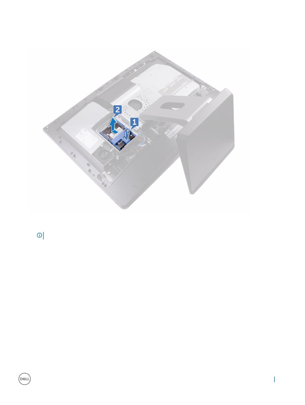
NOTE
: The drive in the top slot of the drive carrier is the primary drive. The procedure for removing both primary and secondary
drive is the same.
1
Follow the procedure in Before working inside your computer.
2 Remove the:
16
Removing and installing components
a USB dongle-bay cover
b back cover
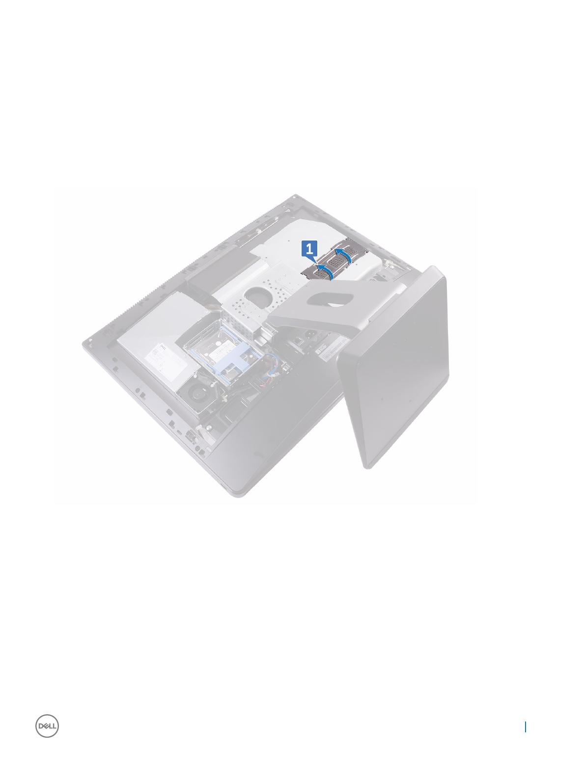
3 Press the strap on the drive assembly [1].
4 Using the straps on the drive assembly, push and lift the drive assembly out of the drive cage [2].
5 Pry the drive bracket to release the tabs on the bracket from the slots on the HDD/SSD [3].
6 Slide the hard HDD/SSD o the drive bracket [4].
NOTE
: Note the orientation of the hard drive so that you can replace it correctly.
Removing and installing components 17

Installing HDD/SSD
NOTE
: The drive installed on the top slot is the primary drive. In case, there is only one drive, install it on the top slot. The
procedure for installing both primary and secondary drives is same.
1 Place the drive into the drive bracket and align the tabs on the bracket with the slots on the drive.
2 Snap the drive bracket into the drive.
3 With the straps facing up, align the drive assembly with the slots on the drive cage.
4 Using the straps pull the drive assembly towards the back of the computer till it snaps into the drive interposer.
5 Install the:
a back cover
b USB dongle-bay cover
6 Follow the procedure in After working inside your computer
System board shield
Removing system-board shield
1 Follow the procedure in Before working inside your computer.
2 Remove the:
a USB dongle-bay cover
b back cover
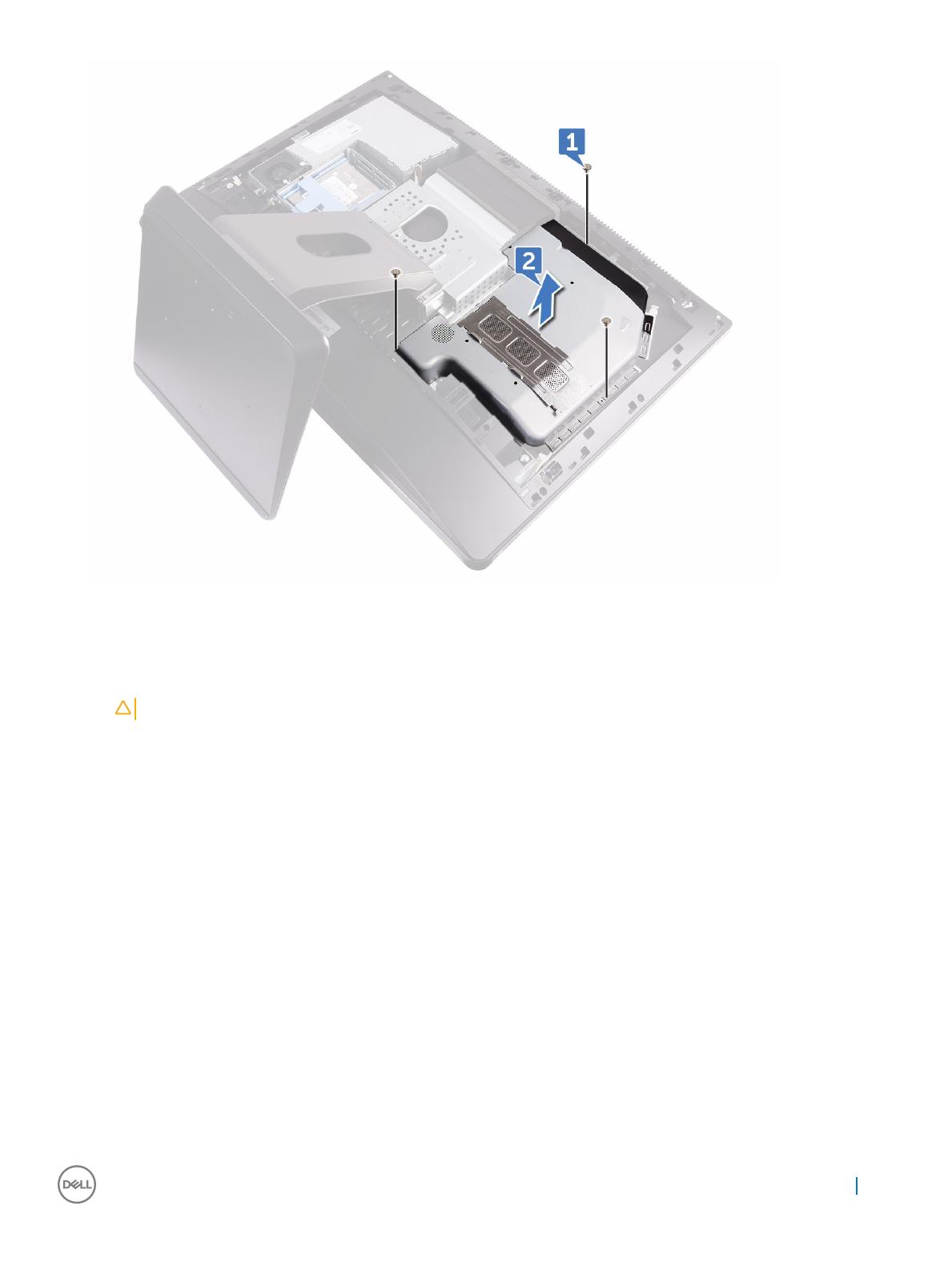
3 Remove the three screws (M3X4) that secure the system-board shield to the middle frame [1].
4 Lift the system-board shield o the middle frame [2].
18
Removing and installing components
Installing system-board shield
1 Align the screw holes on the system-board shield with the screw holes on the middle frame.
CAUTION
: Make sure you do not damage the WLAN antenna when you place the system-board shield.
2 Replace the three screws (M3X4) that secure the system-board shield to the middle frame.
3 Install the:
a back cover
b USB dongle-bay cover
4 Follow the procedure in After working inside your computer
M.2 PCIe SSD
Removing M.2 PCIe SSD
1 Follow the procedure in Before working inside your computer.
2 Remove the:
a USB dongle-bay cover
b back cover
c system-board shield
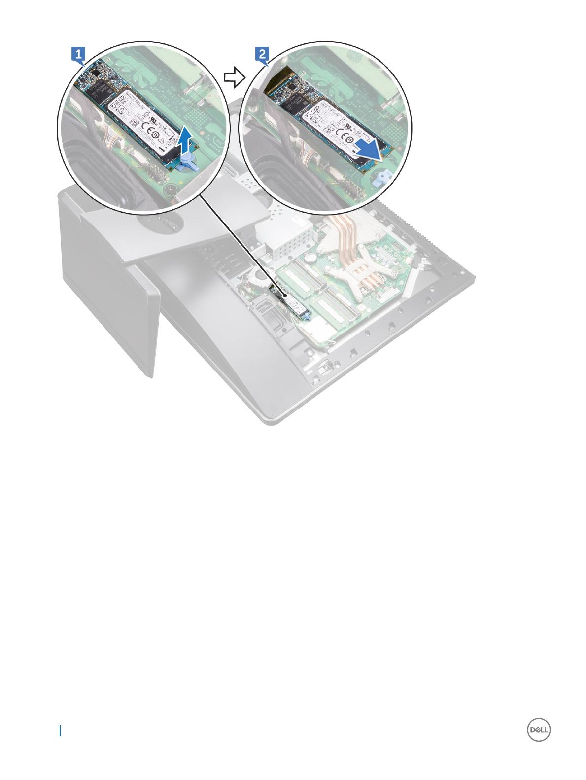
3 Open the securing clip that secures the solid-state drive to the system board [1].
4 Slide and remove the solid-state drive from the solid-state drive slot [2].
Removing and installing components
19
Installing PCIe SSD
1 Align the notch on the solid-state drive with the tab on the solid-state drive slot.
2 Slide the solid-state drive into the solid-state drive slot.
3 Secure the solid-state drive to the system board using the securing clip.
4 Install the:
a system-board shield
b back cover
c USB dongle-bay cover
5 Follow the procedure in After working inside your computer
Memory fan
Removing memory fan
1 Follow the procedure in Before working inside your computer.
2 Remove the:
20
Removing and installing components
/