Potential dangers from accidents during installation and use are divided into the following three
categories. Closely observe these warnings, they are critical to your safety.
Prohibited
Disconnect
Power
Ground
Be sure to do
WARNING:
If the information in this manual is not followed exactly, a re or explosion may result
causing property damage, personal injury or death.
NORITZ AMERICA
CORPORATION
Installation Manual
TANKLESS GAS WATER HEATER
NR83DVC (GQ-2457WS-FFA US)
(Indoor Installation)
DANGER indicates an imminently hazardous situation which,
if not avoided, will result in death or serious injury.
WARNING indicates a potentially hazardous situation which,
if not avoided, could result in death or serious injury.
CAUTION indicates a potentially hazardous situation which,
if not avoided, may result in minor or moderate injury.
DANGER
WARNING
CAUTION
SBB80JW-1
Rev. 05/16
Requests to Installers
• In order to use the water heater safely, read this installation manual carefully, and follow the in-
stallation instructions.
• Failures and damage caused by erroneous work or work not as instructed in this manual are not
covered by the warranty.
• Check that the installation was done properly in accordance with this Installation Manual upon
completion.
•
After completing installation, please either place this Installation Manual in a plastic pouch and
attach it to the side of the water heater (or the inside of the pipe cover or recess box if applicable),
or hand it to the customer to retain for future reference. Also, be sure to ll in all of the required
items on the warranty and to hand the warranty to the customer along with the Owner's Guide.
CAUTION
Low NOx
Approved by
SCAQMD
14 ng/J or 20 ppm
(Natural Gas Only)
FOR USE IN RESIDENTIAL OR MANUFACTURED HOME APPLICATIONS.
Installation must conform with local codes, or in the absence of
local codes, the National Fuel Gas Code, ANSI Z223.1/NFPA 54-
latest edition and/or the Natural Gas and Propane Installation
Code CSA B149.1 - latest edition.
When applicable, installation must conform with the Manufactured
Home Construction and Safety Standard, Title 24 CFR, Part
3280 or the Canadian Standard CAN/CSA-Z240 MH Mobile
Homes, Series M86.
Noritz America reserves the right to discontinue, or change at any
time, the designs and/or specications of its products without notice.

2
1.
Included Accessories
The following accessories are included with the unit.
Check for any missing items before starting installation.
Q’ty
ShapePart
1
each
Part Shape
Q’ty
5
2.
Optional Accessories
The accessories listed below are not
included with the units, but may be necessary
for installation.
Q’ty
ShapePartPart Shape
Q’ty
1
Quick Connect Cord
(QC-2)
1
1
Isolation Valves*
(includes pressure
relief valve)
Pipe Cover
(PC-2S)
Owner's Guide, Warranty,
Installation Manual
(this document)
Part No. Description
4"-CVP-4STR
12"-CVP-12STR
24"-CVP-24STR
36"-CVP-36STR
Adjustable
Part No. Description
CVT-S
Wall Flange
-Female Model
Horizontal Termination
Flange Elbow
Part No. Description
CRCAI-1-F CAIP
Support Strap
CVP-45ELB
CRF-P
Standard Horizontal Kit
FP-5-OUT
CRF-20
Part No. Description
Roof Flashing
(Adapter A)
CRFB-55
Adjustable
90 Elbow
90 Elbow
Straight
Straight
Termination
11"-CVP-11ADJ
16"-CVP-16ADJ
40"-CVP-40ADJ
Rain Cap
CWF-F
Air Intake pipe
Roof Flashing
(Cap)
Roof Flashing
(Base)
CVP-90ELB
SS5-2
Roof Flashing
(Adapter B)
CRFA-40
45 Elbow
Plate
CVP-90ADJELB**
CWF-90ELB**
Horizontal Kit - CVK-H-F
Vertical Kit - CVK-H2-F
Note: Additional vent pieces are available; consult the latest product catalogue for details.
Anchoring Screw
* Isolation valves are necessary for ushing the Heat Exchanger.
They allow for easy ushing of the system.
** "Male to Male Adapter (CVP-ADAPT-M2M)" is necessary for using "Adjustable 90°Elbow (CPV-
90ADJELB)" and "Horizontal Termination Flange Elbow (CWF-90ELB)".
Male to Male Adapter
CVP-ADAPT-M2M

3
G
Quick Connect
Cord
Gas Supply Piping
Cold Water Supply
Hot Water
Remote Controller
*1
Cord
Connector
Cord
Connector
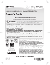
3.
Quick Connect Multi System Installation
• The Quick Connect Multi System allows the installation of two units together utilizing only the Quick
Connect Cord.
The Quick Connect Cord is 6' (2m) long. Install the units 2-18" (50-450mm) apart from each other
to ensure the cord will be able to reach between the units. (See Typical Plumbing diagram).
(If the distance between the two units is too great, not only will the cord not be able to reach,
but the water temperature may also become unstable because of the difference in pipe length
between the two units).
*1 When connecting two units, disconnect
the remote controller connector from
the other unit.
Note: Connect the remote
controller to only one
of the units.
When quick connecting
with a NR83-DVC model,
the remote controller
must be connected to
the NR83DVC (GQ-
2457WS-FFA US)
unit.
System Diagram
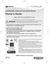
• Insulate the hot wa ter piping to prevent heat loss. Insulate and apply heating materials to the
cold water supply piping to prevent heat loss and freezing of pipes when exposed to excessively
cold temperatures.
Size the piping to allow for the
maximum flow rates of the units.
Distance at center: 16-32" (406-812mm).
Union
Hot Water
Shutoff
Valve
Cold Wa
ter
Distance on sides
2-18" (50-450mm).
Union
Quick Connect
Cord
Pressure
Relief
Valve
Shutoff
Valve
Union
Gas Valve
Shutoff Valve
Leave enough clearance around the plumbing to
apply insulation. It will be necessary to add
bends to the piping to ensure that this clearance
is available.
Make this distance as short
as possible.
*
The hot water temperature
will become unstable as the
pipe length increases.
The backflow preventer is
put up before it diverges.
Typical Plumbing

4
180,000
151,200
2.2
2.5" 2.5"
2.2
172,000
144,500
180,000 BTU
18,000 BTU
182
4.0
1.0 2.5"
10.5"
689
ANSI Z21.10.3-2014/CSA 4.3-2014
15
150
2
NR83DVC (GQ-2457WS-FFA US)
4.
Before Installation
Checkup
• Check the xing brackets and vent pipe yearly for damage or wear. Replace if necessary.
DANGER
Do Not Use Equipment for Purposes Other Than Those Specied
• Do not use for other than increasing the temperature of the water supply, as unexpected accidents
may occur as a result.
Check Water Supply Quality
• If the water supply is in excess of 12 grains per gallon (200 mg/L) of hardness, acidic or otherwise
impure, treat the water with approved methods in order to ensure full warranty coverage.
WARNING
CAUTION
Check the Gas
• Check that the rating plate indicates the
correct type of gas.
• Check that the gas supply line is sized for
180,000 Btuh for this unit.
Check the Power
• The power supply required is 120VAC, at 60Hz.
May result in re or electric shock.
Use Extreme Caution if Using With a Solar Pre-Heater
• Using this unit with a solar pre-heater can lead to unpredictable output temperatures and
possibly scalding. If absolutely necessary, use mixing valves to ensure output temperatures do
not get to scalding levels. Do not use a solar pre-heater with the quick-connect multi-system.
Precautions for Mobile Home Installation
• Verify that the gas supply type matches the gas type listed on the rating plate. If a gas conversion
must be done, follow the instructions listed in the manual.
Precautions on Vent Pipe
• This appliance requires the use of special concentric type vent pipe specied by Noritz America.
Do not attempt to use materials that are not specied for use on this appliance.
Improper venting may result in a re, property damage, or exposure to Carbon Monoxide.
Snow Precaution
• If this product will be installed in an area where snow is known to accumulate, protect the vent termi-
nation from blockage by snow drifts or damage from snow falling off of roofs.

5
5.
Choosing Installation Site
* Locate the appliance in an area where leakage from the unit or connections will not result in damage
to the area adjacent to the appliance or to the lower oors of the structure. When such installation
locations cannot be avoided, a suitable drain pan, adequately drained, must be installed under the
appliance. The pan must not restrict combustion air ow.
* As with any water heating appliance, the potential for leakage at some time in the life of the product
does exist. The manufacturer will not be responsible for any water damage that may occur.
• Locate the vent terminal so that there are no obstacles around the termination and so that exhaust
can't accumulate. Do not enclose the termination with corrugated metal or other materials.
• Avoid places where res are common, such as those where gasoline,
benzene and adhesives are handled, or places in which corrosive gases
(ammonia, chlorine, sulfur, ethylene compounds, acids) are present.
Using the incorrect voltage may result in re or cracking.
• Avoid installation in places where dust or debris will accumulate.
Dust may accumulate and reduce the performance of the unit's fan.
This can result in incomplete combustion.
• Avoid installation in places where special chemical agents
(e.g., hair spray or spray detergent) are used.
Ignition failures and malfunction may occur as a result.
• Carbon Monoxide Poisoning Hazard. Do not install this water heater in a
recreational vehicle or on a boat.
• The manufacturer does not recommend installing the water heater in an
attic due to safety issues.
If you install the water heater in an attic:
•
Make sure the unit will have enough combustion air and proper ventilation.
•
Keep the area around the water heater clean. Dust may accumulate and
reduce the performance of the unit's fan. This can result in incomplete
combustion.
• Place the unit for easy access for service and maintenance.
• A drain pan, or other means of protection against water damage, is
required to be installed under the water heater in case of leaks.
Prohibited
DANGER
WARNING

6
• Avoid installation above gas ranges or stoves.
• Avoid installation between the kitchen fan and stove. If oily
fumes or a large amount of steam are present in the installation
location, take measures to prevent the fumes and steam from
entering in the equipment.
• Install in a location where the exhaust gas ow will not be af-
fected by fans or range hoods.
• Take care that noise and exhaust gas will not affect neighbors.
Avoid installation on common walls as the unit will make some
operational noises while it is running.
• Before installing, make sure that the exhaust ue termination will
have the proper clearances according to the National Fuel Gas
Code (ANSI Z223.1-latest edition) or the Natural Gas and Propane
Installation Code (CSA B149.1).
State of California: The water heater must be braced, anchored or strapped to avoid moving during an
earthquake. Contact local utilities for code requirements in your area or call: 1-866-766-7489 and re-
quest instructions.
Be sure to do
Prohibited
Prohibited
CAUTION
The Commonwealth of Massachusetts: The water heater can be used for hot water only and not in a
combination of domestic and space heating.
For Venting Manufacturers Requirements, see websites or phone numbers listed below:
Noritz N-Vent www.noritz.com
• The water heater is designed for indoor installation only. Never install it
outdoors or in a bathroom, it may be damaged or a re may be caused.
• Consult with the customer concerning the location of installation.
• Install the water heater in an area that allows for the proper clearances
to combustible and noncombustible construction. Consult the rating
plate on the appliance for proper clearances.
• Do not install the water heater in a place where it may be threatened by
falling objects, such as under shelves.
• The water heater must be installed in a place where supply and exhaust
pipes can be installed as directed.
• Do not install the water heater where the exhaust will blow on outer walls
or material not resistant to heat. Also consider the surrounding trees and
animals.
The heat and moisture from the water heater may cause discoloration of
walls and resinous materials, or corrosion of aluminum materials.
Prohibited

7
6.
Installation Clearances
Before installing, check for the following:
Install in accordance with relevant building and mechanical codes, as well as any local, state or
national regulations, or in the absence of local and state codes, to the National Fuel Gas Code
ANSI Z223.1/NFPA 54 – latest edition. In Canada, see the Natural Gas and Propane Installation
Code CSA B149.1 - latest edition for detailed requirements.
WARNING
Item
Distance from combustibles
• Maintain the following clearances
from both combustible and
non-combustible materials.
Check Illustration
• If possible, leave 8" (200mm) or more on
either side of the unit to facilitate inspection.
• If possible, leave 24" (600mm) or more
in front of the unit to facilitate maintenance
and service if necessary.
• If possible, leave 3" (75mm) or more
above and below the vent pipe to facilitate
inspection and repair if necessary.
Securing of space for
repair/inspection
24" (600mm)
or more
8" (200mm)
or more
Distance from
the side
12" (300mm)
or more
2" (50mm)
or more
3" (75mm)
or more
3" (75mm)
or more
4" (100mm)
or more
8" (200mm)
or more

8
7.
Installation
Securing to the wall
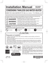
Clearance Requirements from Vent Terminations to Building Openings
* All clearance requirements are in accordance with ANSI Z21.10.3 and the National Fuel Gas Code,
ANSI Z223.1 and in Canada, in accordance with the Natural Gas and Propane Installation Code
CSA B149.1.
DescriptionRef
A=
Clearance above grade, veranda, porch,
deck, or balcony
B=
Clearance to window or door that may
be opened
C=
Clearance to permanently closed window
D=
Vertical clearance to ventilated soffit
located above the terminal within a
horizontal distance of 2 feet (61 cm)
from the center line of the terminal
*
E=
Clearance to unventilated soffit
*
F=
Clearance to outside corner
*
G=
Clearance to inside corner
*
H=
Clearance to each side of center line
extended above meter/regulator assembly
3 ft (91 cm) within a height
15 ft (4.6 m) above the
meter/regulator assembly
I=
Clearance to service regulator vent outlet
3 ft (91 cm)
J=
Clearance to nonmechanical air supply
inlet to building or the combustion air inlet
to any other appliance
K=
Clearance to a mechanical air supply inlet
6 ft (1.83 m)
L=
Clearance above paved sidewalk or paved
driveway located on public property
Clearance under veranda, porch, deck,
or balcony
7 ft (2.13 m)†
M=
1
In accordance with the current CSA B149.1 Natural Gas and Propane Installation Code
2
In accordance with the current ANSI Z223.1 / NFPA 54 National Fuel Gas Code
† A vent shall not terminate directly above a sidewalk or paved driveway that is located between two single
family dwellings and serves both dwellings.
‡ Permitted only if veranda, porch, deck, or balcony is fully open on a minimum of two sides beneath the floor.
* Clearance in accordance with local installation codes and the requirements of the gas supplier.
Clearance to opposite wall is 24 inches (60 cm).
12 in (30 cm)‡
*
12 in (30 cm)
36 in (91 cm)
*
*
*
*
*
*
*
*
3 ft (91 cm) above if within
10 ft (3 m) horizontally
*
12 in (30 cm)
12 in (30 cm)
12 in (30 cm)
36 in (91 cm)
US Direct Vent
Installations
2
Canadian Direct Vent
Installations
1
Vent Terminal
D
E
B
B
F
B
A
G
H
I
C
B
M
K
J
B
B
L
Air Supply Inlet
Area Where Terminal
is Not Permitted
A

9
IllustrationCheck
6. Drill holes for the remaining four screws.
7. Hang the unit again by the rst screw, and then
insert and tighten the remaining four screws.
8. Take waterproong measures so that water does
not enter the building from screws mounting the
device.
• Make sure the unit is installed securely so that it will
not fall or move due to vibrations or earthquakes.
• The distance between the unit and the wall can be
adjusted within the range of 0.4 - 1.8" (10 - 46mm).
Adjust the brackets as necessary to accommodate
the vent system (factory default is 0.4" (10mm)).
1.
Loosen the four screws in the mounting bracket (upper),
match the desired mark to the back of the unit, and
then tighten the screws.
2.
Loosen the four screws in the mounting bracket (lower) and
secure it in the same position as the upper mounting bracket.
3. Drill a single screw hole, making sure to hit a stud.
4. Insert and tighten the screw and hang the unit by
the upper wall mounting bracket.
5.
Determine the positions for the remaining four screws
(two for the top bracket and two for the bottom), and
remove the unit.
• The weight of the device will be applied to the wall. If the strength of the wall is not suf-
cient, reinforcement must be done to prevent the transfer of vibration.
• Do not drop or apply unnecessary force to the device when installing. Internal parts may
be damaged and may become highly dangerous.
• Install the unit on a vertical wall and ensure that it is level.
Locating Screw Holes
Mounting
Structure
• When installing with bare hands, take caution to
not inict injury.
• Be careful not to hit electrical wiring, gas, or water
piping while drilling holes.
Item
CAUTION
Be sure to do
Mounting Bracket
(upper)
Anchoring Screw
Location of Screw Hole
Locating Screw Holes
Installations at Elevations
Above 2,000 ft.(610m).
• Adjust the dip switches as illustrated in the table to
the right if this water heater is installed at an altitude
of 2000 ft. (610m) or higher.
• Disconnect power to the water heater before chang
-
ing the dip switches. Failure to perform this step will
result in a "73" code displayed on the remote control-
ler and a cease in operation. If this occurs, discon-
nect, then reconnect power to the water heater to
reset the system.
Note : Please refer to page 27 for the location of the
dip switch bank.
0.4 - 1.8"
(10 - 46mm)
mounting bracket
(upper)
mounting bracket
(lower)
mark
(0.4" (10mm) intervals)
* Do not change any other dipswitches.
* High elevation adjustment.
65
2,001 - 4,000 ft (611 - 1,220m)
0 - 2,000 ft (0 - 610m)
ON= OFF=
4,001 - 6,000 ft (1,221 - 1,830m)
6,001 - 8,000 ft (1,831 - 2,440m)

10
> 3" (75mm)
(20-75mm)
0.8"-3"
< 0.8"
(20mm)
ოෘ
ოෘ
Straight Termination Installation Precautions.
Note the following vent terminal installation requirements.
• Do not install the vent terminal indoors
• Install the vent terminal with a downward slope
upward
slope
downward
slope
•
Install with the proper length protruding through the wall
•
Avoid storing hazardous
objects near the terminal
Gasoline
Gas
Proper installation.
The red line can be
seen, but not more
than 2.2" (55mm)
from the wall.
Vent terminal
Vent terminal
not far
enough
too far
Snow
drift
Tree
•
Avoid installing the terminal where obstacles
will block it
•
Do not cover the vent terminal with any type of protective
screen or enclosure. Blocked terminals can cause abnor-
mal combustion resulting in undesired performance from
the water heater.
8.
Vent Pipe Installation
• This appliance requires the use of special concentric type vent pipe specied by Noritz America.
Do not attempt to use materials that are not specied for use on this appliance.
WARNING
Be sure to do
CARBON MONOXIDE POISONING
Follow all vent system requirements in accordance with relevant local or state regulation,
or, in the absence of local or state code, in the U.S. to the National Fuel Gas Code ANSI
Z233.1/NFPA 54 – latest edition, and in Canada, in accordance with the Natural Gas and
Propane Installation Code CSA B149.1 – latest edition.
•
Clearance from vent terminal.
If multiple units are installed, the concentric vent terminals must be separated
by a minimum of either 12" (300mm) horizontally or 60" (1.5m) vertically.
Vent terminal
Vent terminal
12" (300mm) or more
60" (1.5m) or more

11
The power must be unplugged when
adjusting the dip switches to switch the
airow amount.
The unit can be adjusted to accommodate longer vent runs; refer to the below table to nd the
maximum vent length based on the number of elbows. Adjust the dip switches according to the vent
condition noted in the tables below.
Note: By default, the unit has been set to the " 1 minimum length" condition. When adjusting the dip
switches for longer vent runs, the BTUH input of the appliance will be reduced by up to 7%.
Maximum Vent Length Adjustment Dipswitches
- Two 90 elbows, maximum length = 3 ft (0.9m)
(with dip switches set at "minimum length" condition)
- Two 90 elbows, maximum length = 29 ft (9m)
(with dip switches set at "maximum length" condition)
[Maximum Vent Length Example]
• Disconnect power to the water heater before changing the dip switches. Failure to perform
this step will result in a "73" code displayed on the remote controller and a cease in operation
.
If this occurs, disconnect, then reconnect power to the water heater to reset the system.
Note : Please refer to page 27 for the location of the dip switch bank.
3
6
9
12
15
18
21
24
27
30
32
35
38
0.90
1.80
2.70
3.60
4.50
5.40
6.30
7.20
8.10
9.00
9.90
10.80
11.70
m 10 2 3 4 5 6ft
Vent length
*
Elbows
1
2
3
4
5
6
7
8
9
10
11
12
13
Number of
pieces**
1
2
3
4
Minimum length
Short length
***
Long length
****
Maximum lengt
h
****
**Table assumes straight vent pieces are 3’ (0.9m) each.
Shorter or longer vent pieces may also be used up to the maximum allowed vent length.
*** The BTUH input of the appliance will be reduced by up to 3%.
****The BTUH input of the appliance will be reduced by up to 6%.
<Maximum Vent Length Congurations>
* Do not change any other dipswitches.
* Vent length condition.
1 Minimum length
7 8
ON= OFF=
2 Short length
3 Long length
4 Maximum length

12
Drain condensate
according to local codes.
Hanger
Straps
Elbow
Slope vent
termination
downwards
Plate
Termination (CVT-S)
Wall Flange
-Female Model
(CWF-F)
Slope vent
downwards
Condensate collector
must be used if the
total vent run exceeds
3' (0.9m).
Horizontal Vent Termination
• Terminate at least 12" (300mm) above
grade or above snow line.
• Terminate at least 7' (2.1m) above a public
walkway, 6' (1.8m) from the combustion air
intake of any appliance, and 3' (0.9m) from
any other building opening, gas utility me-
ter, service regulator etc.
•
Terminate at least 3' (0.9m) above any forced
air inlet within 10' (3m), 1' (0.3m) below, 1' (0.3m)
horizontally from or 1' (0.3m) above any door,
window, or gravity air inlet into any building per
National Fuel Gas Code ANSI Z223.1/NFPA
54 or the Natural Gas and Propane Installation
Code CSA B149.1.
•
Slope the horizontal vent 1/4" (6mm) downwards
for every 12" (300mm) towards the unit.
• Slope the vent termination piece downwards
towards the terminating wall.
•
The integrated condensate collector must be
used for total vent runs in excess of 3' (0.9m).
Remove the cap from the collector prior to at-
taching the drain line.
•
In the Commonwealth of Massachusetts a car-
bon monoxide detector is required for all side
wall horizontally vented gas fuel equipment.
Please refer to Technical Bulletin TB 010606
for full installation instructions.
• Connect the vent pipe rmly so that it will pre-
vent exhaust gases from leaking.
• Steam or condensed water may drip out of the
vent terminal. Dispose of this condensed water
according to local codes and in order to prevent
injury or property damage.
• If this product will be installed in an area where
snow is known to accumulate,protect the vent
termination from blockage by snow drifts or
damage from snow falling off of roofs.
• Support the vent pipe with hangers at a mini-
mum of every 7' (2.1m).
• Make the vertical pipe as short as possible.
• Do not common vent or connect more than
one appliance to this venting system.
•
Terminate at least 12" (300mm) above grade or
snow line.
• Terminate at least 7' (2.1m) above a public
walkway.
• Exceeding the maximum vent length is danger-
ous and may result in bad combustion.
•
Install the vent terminal so that all exhaust is di-
rected to and all intake air is taken from outdoors.
• Do not store hazardous or ammable substanc-
es near the vent terminal.
•
Slope the vent pipe 1/4" (6mm) for every 12"
(300mm) either towards the horizontal termination
or towards the integrated condensate collector.
When using the condensate collector, create a
trap in the drain line and pre-charge it with wa-
ter to prevent exhaust gas leakage.
• Maintain the same vent pipe diameter all the
way to the end.
• Noritz Concentric vent pipe is approved for use
on this appliance with zero clearance to com-
bustibles.
• Use only Noritz specied venting products.
WARNING
Be sure to do
CARBON MONOXIDE POISONING
Do not remove the cap from the condensate collector unless it is being used to drain
condensate. Without the cap in place, ue products could enter the living space.

13
(Combustible material)
External wall,
combustible material.
• Inspection openings are suggested for the vent intake and exhaust
pipes if they are installed in an enclosure. These openings should
be near the entrance and exit of the vent into the enclosure.
• These openings should be 18" x 18" (450mm x 450mm).
Suggested inspection openings
18" x 18" (450mm x 450mm)
When the vent pipe passes through an enclosed space:
Ceiling
Sloping down toward the unit.
Vertical Vent Termination
Drain condensate
according to local codes.
Hanger
Straps
Elbow
Slope vent
Upwards
Firestop
Condensate collector must be
used if the total vent run
exceeds 3' (0.9m).
Elbow
Firestop/
Support
Roof Flashing
(Base and Adapter)
Rain Cap
Air Intake
Pipe
5' (1.5m) or more
WARNING
Prohibited to install 90 degree adjustable
elbow (CVP-90ADJELB) in this portion.
Install 90 degree elbow (CVP-90ELB) only.
• Terminate at least 6' (1.8m) from the combus-
tion air intake of any appliance, and 3' (0.9m)
from any other building opening, gas utility me-
ter, service regulator etc.
• Enclose exterior vent systems below the roof
line to limit condensation and protect against
mechanical failure.
• When the vent penetrates a oor or ceiling and
is not running in a fire rated shaft, a firestop
and support is required.
•
When the vent termination is located not less than
8' (2.4m) from a vertical wall or similar obstruc-
tion, terminate above the roof at least 2' (0.6m),
but not more than 6' (1.8m), in accordance
with the National Fuel Gas Code ANSI Z223.1/
NFPA 54 or Natural Gas and Propane Installa-
tion Code CSA B149.1.
• Provide vertical support every 7' (2.1m).
• Slope the horizontal vent 1/4" for every
12" (300mm) towards the drain tee.
• The integrated condensate collector must be
used for
total vent
runs in excess of 3' (0.9m).
Remove the cap prior to attaching the drain
tubing.
• When 2 units are installed in a Quick Connect
Multi System, maintain a minimum distance of
5' (1.5m) between the vertical terminations.

14
Follow the instructions from the gas supplier.
9.
Gas Piping
Gas Type
The gas type indicated on the water heater rating plate (NG or LP) must match the type of gas being
supplied to the water heater.
Gas Conversions
If the gas type supplied does not match the gas type on the rating plate, obtain a replacement unit with
the proper gas type.
If a gas type conversion must be made, there are conversion kits available for
some models. [The conversion kit shall be installed by a qualied service agency in accordance with
the manufacturer’s instructions and all applicable codes and requirements of the authority having jurisdiction.
The qualied service agency is responsible for the proper installation of this kit. Improper installation of
this kit will void the warranty.]
Meter
The gas meter must be sized properly for the water heater and other gas appliances to operate properly.
Select a gas meter capable of supplying the entire btuh demand of all gas appliances in the building.
The guidelines and examples we have provided in this manual section are for reference only.
The sizing and installation of the gas system for this water heater, as with any gas appliance, is the
sole responsibility of the installer. The installer must be professionally trained to do such work and
must always follow all local and national codes and regulations. Gas line sizing calculations must
be performed for every installation. Please contact Noritz America at 866-766-7489 if you have any
questions or concerns.
CAUTION
Regulators
Ensure that all gas regulators used are operating properly and providing gas pressures within the specied
range of the water heater being installed. Excess gas inlet pressure may cause serious accidents.
CAUTION
Pressure
Check the gas supply pressure immediately upstream at a location provided by the gas company.
Sup-
plied gas pressure must be within the limits shown in the specications section with all gas appliances
operat-
ing. The inlet gas pressure must be within the range specied. This is for the purposes of input
adjust-
ment. Low gas pressure may cause a loss of ame or ignition failure at other appliances in the home, which
may result in unburned gas in the home. Serious accidents such as re or explosion may result.
Measuring Gas Pressure
In order to check the gas supply pressure to the unit, a tap is provided on the
gas inlet. Remove the 9/32” hex head/Philips screw from the tap, and connect
a manometer using a silicon tube. Open up at least 2 xtures and hold in the
maximum manifold pressure button on the circuit board. Please call Noritz for
details.
WARNING

15
Pressure Test
The appliance and its gas connections must be leak tested before placing the appliance in operation.
The appliance must be isolated from the gas supply piping system by closing its individual manual
shutoff valve during any pressure testing of the gas supply piping system at test pressures equal to
or less than ½ psig (3.5 kPa). We do not recommend pressure testing in excess of ½ psig (3.5kPa).
If it must be done, the appliance and its individual shutoff valve must be completely disconnected
from the gas supply piping system during the test process.
Pipe Sizing/Flexible Connectors
A gas shutoff valve must be installed on the supply line. Gas ex lines are not recommended unless
the minimum inside diameter is ¾” or greater and the rated capacity of the connector is equal to or
greater than the BTU capacity of the water heater. Gas piping shall be in accordance with local utility
company requirements and/or in the absence of local codes, use the latest edition of National
Fuel Gas Code (NFPA54GC), ANSI Z223.1. Size the gas line according to total btuh demand
of the building and length from the meter or regulator so that the following supply pressures are
available even at maximum demand.
WARNING
Natural Gas Supply Pressure
Min 4” WC
Max 10.5” WC
LP Gas Supply Pressure
Min 8” WC
Max 14” WC
Reference Tools & Sample Calculations
The tables and samples below are for reference only. The professional sizing and installing the gas
line should always run the appropriate calculations before all installations.
CAUTION
Which Table to Use
• For NG installations with the initial supply pressure at point of delivery (at the meter, for example) is
less than 8” WC, use the 0.5” WC pressure drop table (Table 1).
• For NG installations with the initial supply pressure at point of delivery is greater than or equal to 8”
WC, use the 3.0” pressure drop table (Table 2).
• For all LP installation use (Table 3)
The inlet pressure must be at least 5” WC for NG or 8” WC for LP for all appliances in the gas system.
If the inlet gas pressure drops below 5” WC for NG or 8” WC for LP, the heater may continue to operate,
but the other appliances in the house may experience ame loss or ignition failure, which can result in gas
leakage into the home. Refer to the NFPA 54 for details.
Please contact Noritz for details. For corrugated stainless steel tubing (CSST) capacity tables, please
consult with the manufacturer.

16
Pipe
Size
Length (including ttings)
10' 20' 30' 40' 50' 60' 70' 80' 90' 100' 125'
(3m) (6m) (9m) (12m) (15m) (18m) (21m) (24m) (27m) (30m) (38m)
3/4" 360 247 199 170 151 137 126 117 110 104 92
1" 678 466 374 320 284 257 237 220 207 195 173
1 1/4" 1,390 957 768 657 583 528 486 452 424 400 355
1 1/2" 2,090 1,430 1,150 985 873 791 728 677 635 600 532
2" 4,020 2,760 2,220 1,900 1,680 1,520 1,400 1,300 1,220 1,160 1,020
2 1/2" 6,400 4,400 4,400 3,020 2,680 2,430 2,230 2,080 1,950 1,840 1,630
3" 11,300 7,780 7,780 5,350 4,740 4,290 3,950 3,760 3,450 3,260 2,890
4" 23,100 15,900 12,700 10,900 9,660 8,760 8,050 7,490 7,030 6,640 5,890
Table 1. For Less than 8” WC initial supply pressure
Maximum Natural Gas Delivery Capacity (0.5” Pressure Drop) [Schedule 40 Metalic Pipe]
Values in Table are in Cubic Feet of Gas per Hour (0.60 Specic Gravity, 0.5” Pressure Drop, inlet pressure less than 2psi). Contact your gas
supplier for BTU/Cubic Foot ratings. For simplication of your calculations, 1 Cubic Foot of Gas is approximately equivalent to 1000 BTU.
Table 2. For 8” WC – 10.5” WC initial supply pressure
Maximum Natural Gas Delivery Capacity (3.0” Pressure Drop) [Schedule 40 Metalic Pipe]
Values in Table are in Cubic Feet of Gas per Hour (0.60 Specic Gravity, 3.0” Pressure Drop, 8.0” WC or greater supply pressure, inlet
pressure less than 2psi). Contact your gas supplier for BTU/Cubic Foot ratings. For simplication of your calculations, 1 Cubic Foot of
Gas is approximately equivalent to 1000 BTU.
Instructions
1. Size each outlet branch starting from the furthest
using the Btuh required and the length from the meter.
2. Size each section of the main line using the length to
the furthest outlet and the Btuh required by everything
after that section.
Sample Gas Line
Sample Calculation - (Using 0.5” WC Pressure Drop Table)
Outlet A: 45' (13.5m) (Use 50' (15m)), 50,000 Btuh requires 1/2"
Outlet B: 40' (12m), 65,000 Btuh requires 1/2"
Section 1: 45' (13.5m) (Use 50' (15m)), 115,000 Btuh requires 3/4"
Outlet C: 30' (9m), 35,000 Btuh requires 1/2"
Section 2: 45' (13.5m) (Use 50' (15m)), 150,000 Btuh requires 3/4"
Outlet D: 25' (7.5m) (Use 30' (9m)), 25,000 Btuh requires 1/2"
Section 3: 45' (13.5m) (Use 50' (15m)), 175,000 Btuh requires 1"
Outlet E: 25' (7.5m) (Use 30' (9m)), 180,000 Btuh requires 3/4"
Section 4: 45' (13.5m) (Use 50' (15m)), 355,000 Btuh requires 1 1/4"
Natural Gas
Meter
Noritz Tankless Gas Water Heater
(180,000 Btuh)
Clothes Dryer
(35,000 Btuh)
Barbecue
(50,000 Btuh)
Gas Range Stove
(65,000 Btuh)
10' (3m)
10' (3m)
10' (3m)
10' (3m)
5' (1.5m)
5' (1.5m)
5' (1.5m)
5' (1.5m)5' (1.5m) 5' (1.5m)
Gas Fireplace
(25,000 Btuh)
Section 3 Section 2
Section 1
Outlet A
Outlet B
Outlet C
Outlet D
Outlet E
Section 4
Natural Gas
Meter
Clothes Dryer
(35,000 Btuh)
Barbecue
(50,000 Btuh)
Gas Range Stove
(65,000 Btuh)
10' (3m)
10' (3m)
10' (3m)
10' (3m)
5' (1.5m)
5' (1.5m)
5' (1.5m)
5' (1.5m)5' (1.5m) 5' (1.5m)
Gas Fireplace
(25,000 Btuh)
Instructions
1. Size each outlet branch starting from the furthest
using the Btuh required and the length from the meter.
2. Size each section of the main line using the length to
the furthest outlet and the Btuh required by everything
after that section.
Sample Gas Line
Sample Calculation (Using 3.0” WC Pressure Drop Table)
Outlet A: 45' (13.5m) (Use 50' (15m)), 50,000 Btuh requires 1/2"
Outlet B: 40' (12m), 65,000 Btuh requires 1/2"
Section 1: 45' (13.5m) (Use 50' (15m)), 115,000 Btuh requires 1/2"
Outlet C: 30' (9m), 35,000 Btuh requires 1/2"
Section 2: 45' (13.5m) (Use 50' (15m)), 150,000 Btuh requires 1/2"
Outlet D: 25' (7.5m) (Use 30' (9m)), 25,000 Btuh requires 1/2"
Section 3: 45' (13.5m) (Use 50' (15m)), 175,000 Btuh requires 1/2"
Outlet E: 25' (7.5m) (Use 30' (9m)), 180,000 Btuh requires 1/2"
Section 4: 45' (13.5m) (Use 50' (15m)), 355,000 Btuh requires 3/4"
Section 3 Section 2
Section 1
Outlet A
Outlet B
Outlet C
Outlet D
Outlet E
Section 4
Noritz Tankless Gas Water Heater
(180,000 Btuh)
Pipe
Size
Length (including ttings)
10' 20' 30' 40' 50' 60' 70' 80' 90' 100' 125'
(3m) (6m) (9m) (12m) (15m) (18m) (21m) (24m) (27m) (30m) (38m)
1/2" 454 312 250 214 190 172 158 147 138 131 116
3/4" 949
652
524 448
397 360
331
308 289
273 242
1" 1,787 1,228 986 844 748 678 624 580 544 514 456
1 1/4" 3,669 2,522 2,025 1,733 1,536 1,392 1,280 1,191 1,118 1,056 936
1 1/2"
5,497 3,778
3,034
2,597 2,302
2,085 1,919
1,785
1,675 1,582
1,402
2" 10,588 7,277 5,844 5,001 4,433 4,016 3,695 3,437 3,225 3,046 2,700
2 1/2" 16,875 11,598 9,314 7,971 7,065 6,401 5,889 5,479 1,540 4,856 4,303
3" 29,832 20,503 16,465 14,092 12,489 11,316 10,411 9,865 9,087 8,584 7,608
4" 43678 30,020 24,107 20,632 18,286 16,569 15,243 14,181 13,305 12,568 11,139

17
Table 3. Maximum Undiluted Propane (LP) Delivery Capacity in Thousands of
BtuH (0.5” WC Pressure Drop) [Schedule 40 Metalic Pipe]
For reference only. Please consult gas pipe manufacturer for actual pipe capacities.
Final Check
When the installation is complete, verify that inlet gas pressure for the entire gas system does not
drop below 5” WC for NG or 8” WC for LP at all appliances. This can be tested by turning on all
gas burning appliances including the water heater, then check the inlet pressure at each appliance
to verify all appliances are receiving a minimum of 5” WC for NG or 8” WC for LP. If all appliances
are not receiving the minimum inlet pressure the gas piping system may need to be changed.
CAUTION
Pipe
Size
Length (including ttings)
10' 20' 30' 40' 50' 60' 70' 80' 90' 100' 125' 150' 200'
(3m) (6m) (9m) (12m) (15m) (18m) (21m) (24m) (27m) (30m) (38m) (45m) (60m)
1/2" 275 189 152 129 114 103 96 89 83 78 69 63 55
3/4" 567 393 315 267 237 217 196 185 173 162 146 132 112
1" 1,071 732 590 504 448 409 378 346 322 307 275 252 213
1 1/4" 2,205 1,496 1,212 1039 913 834 771 724 677 630 567 511 440
1 1/2" 3,307 2,299 1,858 1,559 1,417 1,275 1,181 1,086 1,023 976 866 787 675
2" 6,221 4,331 3,465 2,992 2,646 2,394 2,205 2,047 1,921 1,811 1,606 1,496 1,260

18
10.
Water Piping
This appliance is suitable for potable water and space heating applications. Do not use this appliance if any part
has been underwater. Immediately call a qualied service technician to inspect the appliance and replace any part
of the control system and gas control which has been under water.
If the water heater is installed in a closed water supply system, such as one having a backow preventer in the
cold water supply line, means shall be provided to control thermal expansion. Contact the water supplier or a local
plumbing inspector on how to control this situation.
A pressure relief valve must be installed near the hot water outlet that is rated in accordance with and complying
with either The Standard for Relief Valves and Automatic Shutoff Devices for Hot Water Supply Systems, ANSI
Z21.22, or The ANSI/ASME Boiler and Pressure Vessel Code, Section IV ( Heating Boilers ). This pressure relief
valve must be capable of an hourly Btu rated temperature steam discharge of 180,000 Btuh. Multiple valves may be
used. The pressure relief capacity must not exceed 150 psig. No valve shall be placed between the relief valve and
the water heater. The relief valve must be installed such that the discharge will be conducted to a suitable place for
disposal when relief occurs. No reducing coupling or other restriction may be installed in the discharge line. The
discharge line must be installed to allow complete drainage of both the valve and the line. If this unit is installed with
a separate storage vessel, the separate vessel must have its own temperature and pressure relief valve. This valve
must also comply with The Standard for Relief Valves and Automatic Gas Shutoff Devices for Hot Water Supply
Systems, ANSI Z21.22. (in the U.S. only). A temperature relief valve is not required, but if one is used, do not install
the valve with the probe directly in the ow of water. This may cause unwarranted discharge of the valve.
Piping and components connected to the water heater shall be suitable for use with potable water.
Toxic chemicals, such as those used for boiler treatment, shall not be introduced into the potable water.
A water heater used to supply potable water may not be connected to any heating system or components previ-
ously used with a nonpotable water heating appliance.
When water is required in one part of the system at a higher temperature than in the rest of the system, means
such as a mixing valve shall be installed to temper the water to reduce the scald hazard.
Installation and service must be performed by a qualied plumber. In the
Commonwealth of Massachusetts, this product must be installed by a licensed
plumber or gas tter in accordance with the Massachusetts Plumbing and Fuel
Gas Code 248 CMR Sections 2.00 and 5.00. Observe all applicable codes.
• Flush water through the pipe to clean out metal powder, sand and dirt before connecting it.
• Perform the following insulation measures for prevention of freezing.
• Take appropriate heat insulation measures (e.g., wrapping with heat
insulation materials, using electric heaters) according to the climate
of the region to prevent the pipe from freezing.
• Make sure that there are no water leaks from the cold and hot water
supply pipes, then insulate the pipes completely.
• Be sure to also completely insulate the water supply valve and the
cold and hot water connections on the water heater (refer to the g-
ure on the right).
• Do not cover the water drain plug with insulation so that water in the
pipe can be drained. (Refer to the gure in the right.)
•
Use a union coupling or exible pipe for connecting the pipes to reduce the force applied to the piping.
• Do not use piping with a diameter smaller than the coupling.
• When feed water pressure is too high, insert a depressurizing valve, or take
water hammer prevention measure.
• Avoid using joints as much as possible to keep the piping simple.
• Avoid piping in which an air holdup can occur.
• If installing the unit on a roof:
• About lower-level hot water supply
If the unit is installed on a roof to supply water to the levels below, make sure that the water pressure supplied
to the unit does not drop below 29 psi. It may be necessary to install a pump system to ensure that the water
pressure is maintained at this level.
Check the pressure before putting the unit into operation.
Failure to supply the proper pressure to the unit may result in noisy operation, shorter lifetime of the unit, and
may cause the unit to shut down frequently.
Completely insulate
the water inlet and
outlet fittings.
Insulate the water
supply valve completely.
Do not cover the water
drain plug with insulation
so that water in the pipe
can be drained.

19
Supply water piping
•
Do not use PVC, iron, or any piping which has been
treated with chromates, boiler seal or other chemicals.
•
Mount a check valve and a shut off valve (near the inlet).
• In order for the client to use the water heater
comfortably, 98.1 to 491 kPa (14 to 70 PSI) of
pressure is needed from the water supply.
Be sure to check the water pressure. If the
water pressure is low, the water heater cannot
perform to its full capability, and may become a
source of trouble for the client.
Drain piping
• Expansion water may drop from the pressure
relief valve and wet the oor.
If necessary, provide drain piping or use a drain
hose to remove the water.
Hot water piping
• Do not use lead, PVC, iron or any piping which
has been treated with chromates, boiler seal or
other chemicals.
• The longer the piping, the greater the heat loss.
Try to make the piping as short as possible.
• Use mixing valves with low water resistance.
Use shower heads with low pressure loss.
• If necessary, use a pump or other means to en-
sure that the supply water pressure to the inlet
of the heater does not fall below 29 PSI when
the maximum amount of water is being demand-
ed. Also install a pressure meter on the inlet. If
this is not done, local boiling will occur inside
the water heater causing abnormal sounds and
decreasing the durability of the heat exchanger.
Freeze Prevention
• Freezing is prevented within the device automatically unless the outside temperature without wind
is below -30°F (-35°C).
• If this model is installed in an area where the outside temperature can approach freezing conditions
of -30°F (-35°C) or below, then additional freeze protection measures must be used. For temporary
freeze protection measures, refer to the Owner's Guide.
• The freeze prevention heaters will not prevent the plumbing external to the unit from freezing.
Protect this plumbing with insulation, heat tape or electric heaters, solenoids, or pipe covers.
• In order for the freeze prevention heaters to operate, the water heater must have power at all times.
Total Hardness*
:
200 mg/L (12 gpg) or less
Aluminum : 0.05 to 0.2 mg/L or less
Chloride : 250 mg/L or less
Copper : 1 mg/L or less
Iron : 0.3 mg/L or less
Manganese : 0.05 mg/L or less
pH : 6.5 - 8.5
Total Dissolved Solids : 500 mg/L or less
Zinc : 5 mg/L or less
Sulfate ion : 250 mg/L or less
Residual chlorine : 4 mg/L or less
* Maximum limit suggested by Noritz.
Damage to the water heater as a result
of the below is not covered by the Noritz
America Limited Warranty.
• Water in excess of 12 gpg (200mg/L) of
hardness
• Poor water quality (see table to the right)

20
Water Treatment
Water Treatment System
City Water Supply
Pressure
Relief
Valve
Hot Water to Fixtures
Shutoff Valve
Drain
Cold to Water
Heater
Optional Sediment
Filter
Water Treatment Device
Shutoff Valve
Type of Water
Hardness Level
Treatment Device*
Flush Frequency**
Soft
0-1 gpg
1-3 gpg
(0-17 mg/L)
None None
Slightly Hard
(17-51 mg/L)
None None
Moderately
Hard
Hard
3-7 gpg
(51-120 mg/L)
H2Flow or
ScaleShield
H2Flow or
ScaleShield
Once a Year*** or
Flashing the error code****
Once a Year*** or
Flashing the error code****
Once a Year*** or
Flashing the error code****
Once a Year*** or
Flashing the error code****
7-10 gpg
(120-171 mg/L)
Very Hard
10-12 gpg
(171-200 mg/L)
H2Flow or
Water Softener
H2Flow or
Water Softener
Extremely
Hard
> 12 gpg
(> 200 mg/L)
Residential Use Treatment Guidelines
Tankless Gas
Water Heater
* When selecting a treatment device, you must
consult with the device’s spec sheet and
installation manual for guidelines and limitations.
Not all water supplies are compatible -
a water test may be required.
**
Install Noritz Isolation Valves to allow for flushing.
***Flushing is required if a water treatment
device is not installed.
**** The error code "㻯㻌㻌㻌㻏" will be flashing in the
Display Window.
= 1, 2, 3, 4, F
# = 0, 1, 2, 3, 4, 5, 6, 7, 8, 9
▲The illustration is an example. Please check with the actual water heater about the position of piping, and form.
If this water heater will be installed in an application where the supply water is hard, the water must be
treated with either the Noritz H2Flow or ScaleShield or a water softener. Refer to the below tables for
suggested treatment and maintenance measures to be taken based on the water hardness level. If this
water heater will be installed in an application where the supply water is hard, Scale Build-up may cause
damage to the Heat Exchanger. In this case, this water heater detects Scale Build-up in the Heat
Exchanger and then the error code " "* will ash on the Operation Panel. When the error code
" "* is displayed, the Heat Exchanger needs to be ushed to prevent damage from Scale Build-up. Refer
to the "Procedure for ushing the Heat Exchanger" on page 21 or contact Noritz America for more information.
(http://support.noritz.com/ or 866-766-7489)
Damage to the water heater as a result of the items below is not covered by the Noritz America Limited
Warranty.
• Water in excess of 12 gpg (200mg/L) of hardness
• Poor water quality (See the Water Quality List on page 19.)
• The water heater has displayed a " " error code indicating Scale Build-up, but the heat exchanger
has not been ushed.
Note: Water softeners may be regulated by the local water jurisdiction, consult with the manufacturer for
code, sizing, and installation guidelines; the below diagram is for reference only. For more information
about H2Flow and ScaleShield, contact Noritz America at http://support.noritz.com/ or 866-766-7489.
* = 1, 2, 3, 4, F
# = 0, 1, 2, 3, 4, 5, 6, 7, 8, 9
Page is loading ...
Page is loading ...
Page is loading ...
Page is loading ...
Page is loading ...
Page is loading ...
Page is loading ...
Page is loading ...
Page is loading ...
Page is loading ...
Page is loading ...
Page is loading ...
/