Page is loading ...

Betriebsanleitung | Operating instructions | Mode d’emploi | Istruzioni per l'uso |
Instrucciones de servicio | Bruksanvisning
R412012610/05.2014, Replaces: 08.2009, DE/EN/FR/IT/ES/SV
Buskoppler BDC, B-Design
Bus coupler for BDC, B-Design
Coupleur de bus pour BDC, design B
Accoppiatore bus per BDC, design B
Acoplador de bus para BDC, diseña B
Fältbussnod för BDC, B-Design
SERCOS III
DeutschEnglishFrançaisItalianoEspañolSvenska

Anhang
AVENTICS | SERCOS III | R412012610–BDL–001–AB 43
Deutsch
Tabelle 13: Unterstützte Parameter
IDN Name of parameter C Datatype R/W
S-0-0127 CP3 transition ckeck unsigned short RW
S-0-0128 CP4 transition ckeck unsigned short RW
S-0-0021 IDN-list of invalid operation
data for CP2
unsigned long R
S-0-1000 SCP Type & Version unsigned short R
S-0-1002 Communication Cycle time
(tScyc)
unsigned long RW
S-0-1003 Allowed MST losses in
CP3/CP4
unsigned long RW
S-0-1009 Device Control offset in MDT unsigned short RW
S-0-1010 Lengths of MDTs unsigned short RW
S-0-1011 Device Status offset in AT unsigned short RW
S-0-1012 Lengths of ATs unsigned short RW
S-0-1013 SVC offset in MDT unsigned short RW
S-0-1014 SVC offset in AT unsigned short RW
S-0-1017 NRT transmission time unsigned long RW
S-0-1026 Version of communication
hardware
char R
S-0-1035 Error counter Port1 & Port2 unsigned long RW
S-0-1040 SERCOS address unsigned short RW
S-0-1050.x.3 Telegram Assignment AT unsigned short RW
1.S-0-1050.x.3 Telegram Assignment MDT unsigned short RW
1.S-0-1050.x.5 Actual Length of MDT
connection
unsigned short R
S-0-1050.x.5 Actual Length of AT
connection
unsigned short R
S-0-0017 IDN-list of all operation data unsigned long R
S-0-0099 Reset class 1 diagnostic unsigned short RW
S-0-0390 Diagnostic number unsigned long R
S-0-0420 Activate parametrization
level procedure command
(PL)
unsigned short RW
S-0-0422 Exit parameterization level
procedure command
unsigned short RW
S-0-0423 IDN-list of invalid data for
parameterization level
unsigned long R

Anhang
44 AVENTICS | SERCOS III | R412012610–BDL–001–AB
Electronic label
S-0-1300.x.1 Component Name char R
S-0-1300.x.3 Vendor code unsigned short R
S-0-1300.x.4 Device Name char R
S-0-1300.x.5 Vendor Device ID char R
S-0-1300.x.7 Function revision unsigned short R
S-0-1300.x.12 Serial number char R
S-0-1300.x.20 Operational hours unsigned long R
Device structure
S-0-1301.x.0 List of GDP function groups
& Version
unsigned short R
Subdevice
S-0-1302.x.1 FSP Type & Version unsigned long R
S-0-1302.x.2 Function Groups unsigned long R
Basic
S-0-1500.x.1 IO_Control unsigned short RW
S-0-1500.x.2 IO_Status unsigned short R
S-0-1500.x.3 Module Type Code unsigned char R
Digital output
S-0-1502.x.3 Channel Amount PDOUT unsigned short R
S-0-1502.x.4 Channel Width PDOUT unsigned short R
S-0-1502.x.5 PDOUT unsigned char RW
Tabelle 13: Unterstützte Parameter
IDN Name of parameter C Datatype R/W

Contents
AVENTICS | SERCOS III | R412012610–BDL–001–AB 47
English
Contents
1 About This Documentation ......................................... 49
1.1 Documentation validity ......................................................... 49
1.2 Required and supplementary documentation............... 49
1.3 Presentation of information ................................................ 50
1.3.1 Safety instructions ............................................................... 50
1.3.2 Symbols ................................................................................... 51
1.3.3 Abbreviations ......................................................................... 51
2 Notes on Safety ........................................................... 52
2.1 About this chapter.................................................................. 52
2.2 Intended use............................................................................. 52
2.3 Improper use ........................................................................... 53
2.4 Personnel qualifications....................................................... 53
2.5 General safety instructions ................................................. 54
2.6 Safety instructions related to the product and
technology ................................................................................ 55
3 Applications ................................................................. 56
4 Delivery Contents ........................................................ 56
5 Device Description ...................................................... 57
5.1 Overview of the valve system............................................. 58
5.2 Device components................................................................ 59
5.2.1 Bus coupler ............................................................................ 59
6 Assembly ..................................................................... 61
6.1 Assembling the valve system with the bus coupler .... 61
6.1.1 Dimensions ............................................................................. 61
6.2 Labeling the module.............................................................. 62
6.3 Connecting the bus coupler electrically .......................... 62
6.3.1 General notes on connecting the bus coupler ............. 63
6.3.2 Connecting the bus coupler as an intermediate
station ...................................................................................... 64
6.3.3 Connecting the bus coupler as a final station ............. 65
6.3.4 Connecting the bus coupler logic and load supply ..... 66
6.3.5 FE connection ........................................................................ 68

Contents
48 AVENTICS | SERCOS III | R412012610–BDL–001–AB
7 Commissioning and Operation ................................... 69
7.1 Making presettings ................................................................ 69
7.1.1 Setting diagnostic messages ............................................ 69
7.1.2 Switching the tolerance level for valve supply
UQ1 and UQ2 .......................................................................... 70
7.1.3 Selecting the valve supply ................................................. 71
7.2 Configuring the bus coupler network............................... 76
7.3 Test and diagnosis on the bus coupler ............................ 77
7.3.1 Reading the diagnostic display on the bus coupler ... 77
7.4 Commissioning the bus coupler ........................................ 78
8 Disassembly and Exchange ....................................... 80
8.1 Exchanging the bus coupler................................................ 80
9 Care and Maintenance ................................................ 82
9.1 Servicing the modules .......................................................... 82
9.2 Bus coupler maintenance .................................................... 82
10 Technical Data ............................................................. 83
10.1 Characteristics ........................................................................ 83
10.2 Bus coupler .............................................................................. 83
11 Spare parts and accessories ..................................... 84
11.1 Bus coupler .............................................................................. 84
11.2 Power plug for bus couplers............................................... 84
12 Disposal ........................................................................ 84
13 Appendix ...................................................................... 85
13.1 Information on the bus master configuration
with SERCOS III........................................................................ 85
13.2 Operating behavior................................................................. 85
13.3 Start-up behavior ................................................................... 86
13.4 SERCOS Device Description Markup Language
(SDDML)..................................................................................... 86
14 Index ............................................................................. 89

About This Documentation
AVENTICS | SERCOS III | R412012610–BDL–001–AB 49
English
1 About This Documentation
1.1 Documentation validity
These instructions contain important information on the safe
and appropriate assembly, operation, and maintenance of the
bus coupler and how to remedy simple malfunctions yourself.
O Read these instructions completely, especially chapter 2
“For your safety” on page 52, before working with the bus
coupler.
1.2 Required and supplementary
documentation
The product is a system component. Also follow the instructions
for the other system components.
O Only commission the product once you have obtained the
following documentation and understood and complied with
its contents.
Further information on the components can be found in the
online catalog at www.aventics.com/pneumatics-catalog.
Table 1: Required and supplementary documentation
Title Document number Document type
Documentation for the HF03-
LG valve system
R412008233 Instructions
Documentation for the HF04
D-SUB valve system
R412015493 Instructions
System documentation

About This Documentation
50 AVENTICS | SERCOS III | R412012610–BDL–001–AB
1.3 Presentation of information
To allow you to begin working with the product quickly and
safely, uniform safety instructions, symbols, terms, and
abbreviations are used in this documentation. For better
understanding, these are explained in the following sections.
1.3.1 Safety instructions
This documentation contains safety instructions before any
steps that involve a risk of personal injury or damage to
property. The measures described to avoid these hazards must
be observed.
Safety instructions are set out as follows:
W Warning symbol: draws attention to the hazard
W Signal word: identifies the degree of hazard
W Hazard type and source: identifies the hazard type and
source
W Consequences: describes what occurs when the safety
instructions are not complied with
W Precautions: states how the hazard can be avoided
SIGNAL WORD
Hazard type and source
Consequences of non-observance
O Precautions
Table 2: Hazard classes according to ANSI Z 535.6-2006
Safety sign, signal word Meaning
DANGER
Indicates a hazardous situation
which, if not avoided, will certainly
result in death or serious injury.
WARNING
Indicates a hazardous situation
which, if not avoided, could result in
death or serious injury.

About This Documentation
AVENTICS | SERCOS III | R412012610–BDL–001–AB 51
English
1.3.2 Symbols
The following symbols indicate information that is not relevant
for safety but that assists in comprehending the documentation.
1.3.3 Abbreviations
This documentation uses the following abbreviations:
CAUTION
Indicates a hazardous situation
which, if not avoided, could result in
minor or moderate injury.
NOTICE
Indicates that damage may be
inflicted on the product or the
environment.
Table 3: Meaning of the symbols
Symbol Meaning
If this information is disregarded, the product cannot be
used or operated optimally.
O
Individual, independent action
1.
2.
3.
Numbered steps:
The numbers indicate sequential steps.
Table 4: Abbreviations
Abbreviation Meaning
VS Valve system
EP end plate End plate with electrical and pneumatic connections
P end plate End plate with pneumatic connection
Table 2: Hazard classes according to ANSI Z 535.6-2006
Safety sign, signal word Meaning

Notes on Safety
52 AVENTICS | SERCOS III | R412012610–BDL–001–AB
2 Notes on Safety
2.1 About this chapter
The product has been manufactured according to the accepted
rules of current technology. Even so, there is risk of injury and
damage to equipment if the following chapter and safety
instructions of this documentation are not followed.
O Therefore, read these instructions completely before
working with the product.
O Keep these instructions in a location where they are
accessible to all users at all times.
O Always include the documentation when you pass the
product on to third parties.
2.2 Intended use
The product is an electropneumatic system component.
The product may be used as follows:
O only for industrial applications (class A). An individual
license must be obtained from the authorities or an
inspection center for systems that are to be used in a
residential area (residential, business, and commercial
areas). In Germany, these individual licenses are issued by
the Regulating Agency for Telecommunications and Post
(Regulierungsbehörde für Telekommunikation und Post,
Reg TP).
O within the performance limits listed in the technical data.
The product is intended for professional use only.
Intended use includes having read and understood this
documentation, especially the chapter “Notes on Safety”.

Notes on Safety
AVENTICS | SERCOS III | R412012610–BDL–001–AB 53
English
2.3 Improper use
Any use other than that described under Intended use is
improper and is not permitted.
If unsuitable products are installed or used in safety-relevant
applications, this may result in unintended system operating
states that could lead to injuries and/or equipment damage.
Therefore, only use a product in safety-relevant applications if
such use is specifically stated and permitted in the product
documentation. For example, in areas with explosion protection
or in safety-related components of control systems (functional
safety).
AVENTICS GmbH is not liable for any damages resulting from
improper use. The user alone bears the risks of improper use of
the product.
It is considered improper use when the bus coupler
W is used for any application not stated in these instructions,
or
W is used under operating conditions that deviate from those
described in these instructions,
W is changed or converted.
2.4 Personnel qualifications
The work described in this documentation requires basic
electrical and pneumatic knowledge, as well as knowledge of the
appropriate technical terms. In order to ensure safe use, these
activities may therefore only be carried out by qualified technical
personnel or an instructed person under the direction and
supervision of qualified personnel.
Qualified personnel are those who can recognize possible
hazards and institute the appropriate safety measures, due to
their professional training, knowledge, and experience, as well
as their understanding of the relevant regulations pertaining to
the work to be done. Qualified personnel must observe the rules
relevant to the subject area.

Notes on Safety
54 AVENTICS | SERCOS III | R412012610–BDL–001–AB
2.5 General safety instructions
W Observe the regulations for accident prevention and
environmental protection.
W Observe the safety instructions and regulations of the country
in which the product is used or operated.
W Only use AVENTICS products that are in perfect working
order.
W Follow all the instructions on the product.
W Persons who assemble, operate, disassemble, or maintain
AVENTICS products must not consume any alcohol, drugs,
or pharmaceuticals that may affect their ability to respond.
W To avoid injuries due to unsuitable spare parts, only use
accessories and spare parts approved by the manufacturer.
W Comply with the technical data and ambient conditions
listed in the product documentation.
W If unsuitable products are installed or used in safety-
relevant applications, this may result in unintended system
operating states that may lead to injuries and/or equipment
damage. Therefore, only use a product in safety-relevant
applications if such use is specifically stated and permitted
in the product documentation.
W You may only commission the product if you have
determined that the end product (such as a machine or
system) in which the AVENTICS products are installed
meets the country-specific provisions, safety regulations,
and standards for the specific application.

Notes on Safety
AVENTICS | SERCOS III | R412012610–BDL–001–AB 55
English
2.6 Safety instructions related to the product
and technology
W Do not place any mechanical loads on the device under any
circumstances. Do not place any loose objects on it.
W Ensure that the power supply is within the stipulated
tolerance for the modules.
W Observe the safety notes in the operating instructions for
your valve system.
W A 24 V power pack supplies all components with electricity.
The power pack must be fitted with a safe isolation in
accordance with EN 60742, VDE 0551 classification. The
corresponding electrical circuits are thus SELV/PELV
circuits in accordance with IEC 60364-4-41.
W Switch off the operating voltage before connecting or
removing the plugs.
During assembly
W The warranty only applies to the delivered configuration. The
warranty will not apply if the product is incorrectly assembled.
W Always make sure the relevant system component is not
under pressure or voltage before assembly or disassembly.
Ensure that the system is prevented from power restoration
during assembly work.
W Ground the modules and valve system. Observe the
following standards when installing the system:
– DIN EN 50178, classification VDE 0160
– VDE 0100
During commissioning W Installation may only be performed in a voltage-free and
pressure-free state and only by a qualified technician. In
order to avoid accidents caused by dangerous movements
of the actuators, electrical commissioning may only be
carried out in a pressure-free state.
W Do not put the system into operation before it is completely
assembled as well as correctly wired and configured, and
after it has been tested.
W The device is subject to the restrictions of the IP 65
protection class. Before commissioning, make sure that all
the connection seals and plugs are leaktight to prevent
fluids and foreign bodies from penetrating the device.

Applications
56 AVENTICS | SERCOS III | R412012610–BDL–001–AB
During operation
W Make sure that there is a sufficient exchange of air or enough
cooling if your valve system has any of the following:
– Full equipment status
– Continuously loaded solenoid coils
During cleaning W Never use solvents or strong detergents. Only clean the
device using a slightly damp cloth. Only use water and, if
necessary, a mild detergent.
3 Applications
The bus coupler is used to electrically control valves via the
SERCOS III real-time Ethernet system.
The bus coupler is designed for use as a slave only on a
SERCOS III network in accordance with IEC 61158/61784.
4 Delivery Contents
The following is included in the delivery contents of a configured
valve system:
W 1 valve system according to configuration and order
W 1 set of operating instructions for the valve system
W 1 set of operating instructions for the bus coupler
The following is included in the delivery contents of a bus
coupler parts kit:
W 1 bus coupler with seal and 2 mounting screws
W 1 set of operating instructions for the bus coupler
The VS is individually configured. You can find the exact
configuration in the AVENTICS Internet configurator under
your order number.

Device Description
AVENTICS | SERCOS III | R412012610–BDL–001–AB 57
English
5 Device Description
The bus coupler allows you to control the VS via a SERCOS III
real-time Ethernet system. In addition to connections for data
lines and power supplies, the bus coupler also enables you to
set various parameters, and permits diagnosis via LEDs. A
detailed description of the bus coupler can be found in the
chapter “Device components” from page 59.
The following overview outlines the entire valve system and its
components. The VS itself is described in separate operating
instructions.

Device Description
58 AVENTICS | SERCOS III | R412012610–BDL–001–AB
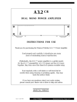
5.1 Overview of the valve system
The valve system consists of the following parts as illustrated in
Fig. 1 (depending on the order):
Fig. 1: Overview: bus coupler sample configuration with assembled VS
1 Bus coupler, B-design type
2 VS EP end plate
3 Valve terminal
1)
4 FE connection 4 + 0.5 Nm
1)
With separate operating instructions
4
1
2
3

Device Description
AVENTICS | SERCOS III | R412012610–BDL–001–AB 59
English
5.2 Device components
5.2.1 Bus coupler
Fig. 2: Bus coupler overview
1 LED displays for diagnostic messages
2 Bus slave label
3 X71 (BUS IN) connection for the bus coupler to control the valves
1)
1)
For plug assignment, see pages 63 and 66.
4 X72 connection (Ethernet) for the bus coupler
1)
5 X10 connection (POWER) to supply power to the valve solenoids
6 Screw cap A 0.6 + 0.2 Nm: DIP switch S1 (diagnosis settings)
7 Screw cap B 0.6 + 0.2 Nm: sliding switch S2 (valve assignment for power supply)
8 FE connection 4 + 0.5 Nm
9 Pocket for slide-in labels (see “Spare parts and accessories” on page 84)
2
1
3
7
4
5
6
8
9
9

Device Description
60 AVENTICS | SERCOS III | R412012610–BDL–001–AB
The bus coupler is designed for use as a slave only on a
SERCOS III network.
SERCOS III address A switch is not required to set the SERCOS III address.
The bus coupler supports automatic address assignment of the
SERCOS address in accordance with SERCOS III. The address is
stored permanently. Factory setting: address (decimal) 55
Transfer rate The transfer rate is 100 Mbit/s full duplex.
Diagnosis The logic and valve control power supplies are monitored. If the
valve supply voltages fall below a set limit, a diagnostic signal
will be generated and reported via the diagnostic LED and the
diagnostic information.
Number of valves that
can be controlled
The bus coupler has 32 valve outputs. This limits the maximum
number of controllable valve solenoids.
Either 16 double solenoid or 32 single solenoid valves can be
controlled in this manner. Valve combinations are also possible.
SERCOS III All SERCOS III standards and guidelines can be found in the
SERCOS International e. V. specifications.
The module supports SERCOS III V1.1.1.
Use of switches or hubs in a SERCOS III network is only
permissible with special types.
The module has two Ethernet twisted pair connections
according to 802.3u with auto-negotiation and auto-crossing
that are connected via an integrated, manageable 3-port switch
(2 external ports, 1 internal port).
Certification The device is certified in accordance with the specifications of
the user organization SERCOS International e. V.

Assembly
AVENTICS | SERCOS III | R412012610–BDL–001–AB 61
English
6 Assembly
6.1 Assembling the valve system with the bus
coupler
You will receive your individually configured valve system
completely fitted with all components:
W Valve terminal
W Bus coupler
The operating instructions accompanying the VS describe in full
how to assemble the entire valve system. Any mounting
orientation may be used with the VS. The dimensions of the
complete VS vary according to module equipment (see Fig. 3).
6.1.1 Dimensions
Fig. 3: Dimensioned drawing for the valve system (bus coupler and valves)
Dimensions A and B depend on the valve block used.
135
A + 33
B + 33
933

Assembly
62 AVENTICS | SERCOS III | R412012610–BDL–001–AB
6.2 Labeling the module
Bus coupler O Inscribe the address provided/used for the bus coupler on
the bus coupler in the BTN field.
Slide-in pockets for labels to identify the push-in fittings are
located on the housing (see “Spare parts and accessories” on
page 84).
Fig. 4: Label areas on the bus coupler
6.3 Connecting the bus coupler electrically
CAUTION
Applied voltage
Danger of injury from electric shocks.
O Make sure the relevant system component is not under
voltage or pressure before electrically connecting
modules to the valve terminal.

Assembly
AVENTICS | SERCOS III | R412012610–BDL–001–AB 63
English
6.3.1 General notes on connecting the bus coupler
Use pre-assembled plug connections and cables to connect
the modules.
O Use D-coded plugs for the bus coupler.
O Observe the pin assignments in Table 5 if you do not use
pre-assembled plug connections and cables.
NOTICE
Faulty wiring
Faulty wiring can lead to malfunctions as well as damage to
the bus system.
O Unless otherwise stipulated, comply with the SERCOS
International e. V. construction and design directives.
O Only a cable that meets the Ethernet specifications as
well as the connection speed and length requirements
should be used.
O In order to assure the protection class, shielding, and the
required strain relief, the cable and plug assembly
should be done professionally.
NOTICE
Current flow in shield due to differences in potential
Compensating currents caused by differences in potential
must not flow through the shield of the SERCOS III cable, as
this will cancel the shielding, which could damage the line
and the connected bus coupler.
O If necessary, connect the grounding points for the system
using a separate line.
/