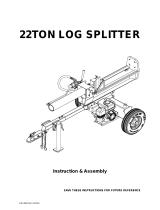
SP-LS22

Steele SP-LS22 Owner's manual

  • Hello! I am an AI chatbot trained to assist you with the Steele SP-LS22 Owner's manual. I’ve already reviewed the document and can help you find the information you need or explain it in simple terms. Just ask your questions, and providing more details will help me assist you more effectively!
_'s Manual
22 Ton
Spfitter
WARNING!ToReduceTheRiskOf Injury,User |
MustRead And UnderstandInstruction Manual.
J
FORSERVICECALL:
SP-LS22 ..M.E,o_Z:888-896-6881
WARNING
Read this manual.
Serious injury or death can result if safety instructions are not followed,
Engine is shipped without oil.
-Before startingengine, fillwithSAE 10W-30 motoroil.
-See engine manual for engine oil capacity.
Hydraulic reservoir is shipped with oil.
-When addingoil, checkoi! level and make sure there is enoughoil before
you start the unit.
Closely inspect all log splitter components.
-If you have damaged componentsthen: Contact the freight company that
delivered the unit and file a claim
, i
Hazard Icons and Definitions
II
It It
Ii 11
1 CAUTION
This is the safety alert symbol, it is used tq
alert you to potential personal injury hazards.
Obey all safety messages that follow this
symbol to avoid possible injury or death.
DANGER (red) indicates an imminently
hazardous situation which, if not avoided, will
result in death or serious injury.
WARNING (orange)indicates a potentially
hazardous situation which, if not avoided,
could result in death or serious injury.
CAUTION (yellow)indicates a potentially
hazardous situation which, if not avoided,
may result in minor or moderate injury.
CAUTION (yellow) used without the safety
alert symbol indicates a potentially
hazardous situation which, if not avoided.
may result in property damage.
TABLEOFCONENS
&
&
&
ImportantSafetyRules...................................................... 4-5
MachineComponentDefinitions........................................... 6
OperationInstructions....................................................... 7-9
ProperOperationoftheLogSplitter............................. 7
&
HorizontalandVerticalOperatingModes 8
***********************
Howto Splitthelogwithslantsurface......................... 9
MaintenanceandStorage................................................... 10
Troubleshooting............................................................. ,,.:...11
Specifications....................................................................... 12
AssemblyInstruction............................................................. 13-15
PartsBreakdown.................................................................... 16-18
A IMPORTANT SAFETY RULES I
WARNING
1.) Read this manual completely.
Serious injury or death can result if safety instructions are not followed.
Everyone who operates the log splitter must read and completely understand all
safety rules, operating instructions, and maintenance instructions.
You must be I6 or older to operate this machine. Keep untrained people away.
-Shut engine off before leaving tog splitter unattended.
2.) Crush hazard.
Wedge can cut through skin and break bones. Keep both hands away from
wedge and endplate.
-Serious accidents can happen when other people are allowed inside the work
zone. Keep everyone else out of the work zone while operating control valve.
-Do not wear loose clothing. It can get tangled in moving parts of log splitter.
-Only use the log splitter in daylight to prevent sight obstruction.
3.) Flying objects.
Pieces of log may fly out while
injury can occur.
splitting. Wear safety glasses. Serious eye
4.) Skin injection hazard.
High pressure fluid can inject under skin resulting in serious injury including
amputation.
-Make sure all fittings are tight before applying pressure. Relieve system
pressure before servicing.
-Do not check for leaks with hand. Instead, use a piece of cardboard to check
for leaks_
-If skin injection happens, seek immediate "Surgical Treatment".
5.) Towing hazard.
Serious injury or death can occur if towing safety rules are not followed.
-Review towing safety warnings in your towing vehicle manual.
-Drive safely. Be aware of the added length of the log splitter.
-Never ride or transport cargo on the log splitter.
-Drive the vehicle with the log splitter securely attached.
-Turn off the vehicle before leaving the log splitter unattended,
-Choose a level surface to operate the log splitter.
-Block the log splitter wheels to prevent unintended movement.
-Never tow or operate this splitter while under the influence of alcohol, drugs, or
medication.
Save These Instructions
I" IMPORTANT SAFETY RULES
WARNING
6.) Risk of fire and explosion.
Hot exhaust fumes from engine can cause fire. Gasoline is highly flammable
and explosive. You can be burned or seriously injured when handling fuel.
-Position muffler at least 7 feet from combustible objects.
-Before adding fuel, stop the engine and keep heat, sparks, and flame away.
Do not add fuel when engine is running or still hot. No smoking near engine.
-Do not pump fuel directly into engine at gas station. Static charge can build
and ignite fuel. Use a safety approved fuel container to transfer gas to the
engine. Wipe up fuel spills immediately.
-Only store and handle fuel outdoors. Gasoline vapors can ignite if they
collect inside an enclosure. Explosion can result.
-Do not change or add to exhaust system. Fire can result.
-Do not change or add fuel tanks or fuel lines. Fire can result.
-Before each use, check fuel tank and fuel lines for leaks. Any fuel leak is a
fire hazard. Fix any fuel leaks before starting engine.
-During transportation take precautions to make sure machine will not tip over
and cause a fuel leak fire hazard.
==
7.) Breathing hazard.
Poisonous fumes from engine can kill you. Do not operate indoorseven if
ventilated. For outdoor use only.
CAUTION
1.) Hot muffler.
You can be burned by muffler.
Do not touch,
Save These Instructions
I MACHINE COMPONENT DEFINITIONS 1
1.) 2" Coupler. Attaches the log splitter to your vehicle, Fits only 2" hitch balls.
2.) Hydraulic Cylinder. The hydraulic cylinder has a 4½" bore and a 23" stroke. It is rated to
3500 psi.
3.) Control Valve Handle, Use the control valve handle to move the wedge slide forward and
backward.
4.) Wedge, The wedge features wedge wings and a taper that makes splitting easier.
5.) Log Cradle, Keeps the log on the beam without operator assistance.
6.) Beam, The beam is made of 6" wide flange beam (also called I-Beam).
7.) Engine. The air cooled engine powers the hydraulic pump.
8.) Tires. Maximum rated speed is 30 mile per hour.
9.) Gear Pump, The gear pump makes the hydraulic oil flow through the system.
10.) Leg, The leg supports the log splitter while operating. The leg should be raised while towing
(see Operation Instructions).
11.) Safety Chains. A safety feature to prevent loss of log splitter while towing.
I,,
A OPERATION
Proper Operation of the Log Splitter
1.)
2,)
INSTRUCTIONS
Load a log onto the beam and against the endplate.
Serious accidents can happen when other people are allowed inside the work zone. Keep
everyone else out of the work zone while operating control valve.
3.) Make sure hands are clear of crush hazard zones.
4.) Push control valve handle FORWARD to split log.
5,) Push control valve handle BACKWARD to return wedge to its odginal position.
6.) Clear the split wood from the work zone.
1
!
A WARNING
Crush hazard.
Wedge can cut through skin and break bones. Keep both hands away from
wedge and beam slide.
-Serious accidents can happen when other people are allowed inside the work
zone. Keep everyone else out of the work zone while operating control valve.
-Do not wear loose clothing. It can get tangled in moving parts of log splitter.
-O_ly use the log splitter in daylight so you can see what you are doing.
A WARNING
Towing hazards.
Serious injury or death can occur if towing safety rules are not followed.
-Review towing safety warnings in your towing vehicle manual.
-Drive safely. Be aware of the added length of the log splitter.
-Never ride or transport cargo on the log splitter.
-Drive the vehicle with the log splitter securely attached.
-Turn off the vehicle before leaving the log splitter unattended.
-Choose a level surface to operate the log splitter.
-Block the log splitter wheels to prevent unintended movement.
-Never tow or operate this log splitter while under the influence of alcohol,
drugs, or medication.
7 '
A OPERATION INSTRUCTIONS
For Horizontal Using
Rotate rear leg down
and slide the lock pin
Beam end handle
For Vertical Using
1. Pulling beam lock pin
2. Lift the beam at the end side,
and Rotate it up slowly
Beam lock pin
/
For Vehicle towing
Press handle down
and lock tightly
Hook safety chain
to towing vehicle
Raise front leg up
and slide the lock pin
Rotate rear leg up
and slide the lock pin
,& OPERATION INSTRUCTIONS
HOW TO SPLIT A LOG WITH AN ANGLED EDGE
MAINTENANCE AND STORAGE
Before performing maintenance, the !og splitter must be placed in maintenance mode.
1.) Turn off engine.
2.) Move the control valve handle forward and backward to relieve hydraulic pressure.
_ After performing maintenance, make sure all guards, shields, and safety features are put back
in place. Failure to follow this warning can result in serious injury.
Refer to the engine owner's manual for engine maintenance.
What When How
Hoses Each Use Inspect for exposed wire mesh and leaks. Replace
all worn or damaged hoses before starting engine
Hydrau ic Fittings Each Use Inspect for cracks and leaks. Replace all damaged
fittings before starting engine
Nuts and Bolts Each Use Check for loose bolts
.....Beam Each Use .................... Apply grease to beam surface
Moving Parts Each Use Clear debris
,AWARNING
Skin injection hazard.
High pressure fluid can inject under skin resulting in
serious injury including amputation.
-Make sure all fittings are tight before applying
pressure. Relieve system pressure before
servicing.
-Do not check for leaks with hand. Instead, use a
piece of cardboard to check for leaks.
-If skin injection happens, seek immediate
"Surgical Treatment".
10
TROUBLESHOOTING !
Problem
Cylinder rod will not move SOLUTION: A,D,E,H,J
Slow cylinder rod speed when extending or SOLUTION:A,B,C,H,I,K,L
retracting
Wood will not split or splits extremely slowly SOLUTION: A,B,C,F,I,K
Engine bogs down during splitting SOLUTION: G,L
Engine stalls under low load condition SOLUTION: D,E,L,M
Cause Solution
A-Insufficient oil to pump Check oil level in reservoir
B-Air in oil Check oil level in reservoir
C-Excessive pump inlet vacuum Check pump inlet hose for blockage or kinks
D-Blocked hydraulic lines Flush and clean the splitter hydraulic system
E-Blocked control valve Flush and clean the splitter hydraulic system
F-Low control valve setting Adjust control valve with a pressure gauge
G-High control valve setting Adjust control valve with a pressure gauge
H-Damaged control valve Return control valve for authorized repair
I-Internal control valve leak Return control valve for authorized repair
J-Internal cylinder leak Return cylinder for authorized repair
K-Internally damaged cylinder Return cylinder for authorized repair
L-Engine Control out of adjustment Adjust idle control nuts
M-Engine is loaded during idle down mode Use shorter log length (24" or less) to allow
engine to speed up before contact.
11"
SPECIFICATIONS l
Maximum Pressure ...................
Maximum Flow ......................
Hydraulic Fluid Capacity ...........
Hydraulic Fluid Type ................
Coupler Size ...........................
Maximum Towing Speed ............
Maximum Log Length ...............
Maximum Log Weight ...............
Hydraulic Cylinder Bore ............
Hydraulic Cylinder Stroke ..........
Maximum Log Diameter ............
3500 psi
8 gpm
2.5 gallons or the level
of the oil in the middle of
oil window on oil tank.
10wt AW32, ASLE
H-150, or ISO32
2" Ball
30MPH
24 in
100 Ib
in
23 in
12in
The manufacturer reserves the right to make improvements in
design and/or changes in specifications at any time without
incurring any obligation to install them on units previously sold.
12
l
ASSEMBLY
Open Shipping Crate
1. Set the shipping crate on a solid, flat surface.
2. Carefully cut the shipping bands and remove lid of shipping crate.
3. Using two people to lift, carefully remove the engine, oil tank, wheels, tow bar, support legs, and
hardware. (For parts reference see page16-18 in manual)
4. Leave the hydraulic cylinder/log cradle in the shipping crate until step 5 in the assembly process.
5. Locate all hardware before beginning assembly.
STEP 1: WHEEL ASSEMBLY
Fix the wheel to the oiltank (#39) axle by a fiat
washer 020 (#74), slotted nut M16x1.5 (#110),
cotter {oin O4x36 (#52) and attach the axle cap
(#101),
39
ATTACH TOW BAR AND SUPPORT
LEG
Fix the support leg (#62) to the tow bar (#30) by
a pin(#42) and handle wheel (#105).
STEP 3: ATTACH TOW BAR TO OIL TANK
Fix the tow bar to the oil tank by using4 sets of
hex boltM12x40 (#31), fiat washer O12 (#3) and
lock nut M12 (#67).
STEP 4: ASSEMBLE REAR SUPPORT LEG
Fix the rear supportleg (#34) to the tow bar by using
hex bolt M10x75 (#36), lock nut M10 (#32), fiat
washer O10 (#97). Slide in hitch pin (#35) and
secure with R pinO3x55 (#26).
36 32 97
26
13
STEP 5: ATTACH HYDRAULIC CYLINDER
LOG CRADLE
Assemble the Beam to the tow bar, secure with
cotter pin O4x40 (#12) & hitch pin (#37).
STEP 6: ATTACH ENGINE
!. Assemble the engine to the oil tank by using
hex bolt M8x55 (#48), flat washer O8 (#45), lock
washer 08 (#46) and lock nut M8 (#57).
2. Place 4 polyurethane blocks (#t03) and big
fiat washer O10 (#102) between the engine and
mounting plate.
STEP 7: ATTACH BALL COUPLER &
CHAIN
I. Attach the coupler (#28) to the tow bar by
using hex bolt M12x80 (#43), fiat washer O12
(#3) and lock nut M12 (#67)_
2_Attach two chains (#41) to the tow bar by using
hex bolt M12x90 (#40), fiat washer O12 (#3),
lock nut M12 (#67) and thick fiat washer O12
(#68),
68
28
STEP 8: ATTACH WHEEL FENDERS
Attach two wheel fenders (#72) to the oil tank
using hex bolt M10x25 (#73), flat washer O10
(#97), lock washer Ot0 (#33) and lock nut M10
(#32).
14
STEP 9: ATTACH HYDRAULIC HOSES
1. Thread the outlet connector (#59) to the top of the gear pump (#47). Use Teflon tape to ensure tight fit.
2. Place an O ring (#61) onto the exposed threads of the outlet connector. Then attach hose (#13) to outlet
connector.
3. Attach hose (#t5) to the port on the oil tank. Place an O ring (#6t) on the port and tighten the hose using
Teflon tape.
4, Attach the oil pipe (#60) to the bottom of the gear pump (#47) by the clamp (#78).
15 13
21
15
23
25 26 27
7 18
29
107 32 5
67
99
t00
73 96
26
72
11
89
t2
70
PARTS LIST
Re_ Description Qty
1 I Beam 1
! BoltM12x55 12
.... 3...... Flat Washer O12 20
__ Hex Thick Nut M12 12
5 I Wedge Slide 1
6
7
9 1
10
12
13
16
18
19
20
2
2
4
4
4
2
2
1
1
1
1
1
3
1
1
Ref#
Description
Breather Cap
Oil Tank
BoltM12x90
Safety Chain with Hook
Pin
Keeper Spacer
Keeper Plate
Lock Washer 024
Flat Washer 024
Hex Nut M24
Axle Outside Bushing
Axle Cover
Hydraulic Hose (Valve-Pump)
Control Valve
Hydraulic Hose (Valve-Oil Tank)
Valve Handle
17 Pin 5x25
Split Pin 2x10
Pin 5x16
Valve A Joiner
o
I 38
4o
4t
42
43
45
46
47
49
51
52
53
54
55
56
57
Bolt M12x80
Outlet oiltube assembly
Flat Washer 08
LockWasher 08
Gear Pump
BoltMt0x60
Split Pin4x40
Compositebearing
Wheel / Tire Assembly
Split Pin4x36
Engine 9HP
Valve Handle Connector
Round-head BoltMSx45
Plate
Hex Lock Nut M8
21
22
23
24
25
26
27
29
31
33
35
36
37
Combination Washer O 14
Bolt Connector
Hydraulic Hose (Valve-Cylinder)
Cylinder
Flat Washer 020
R Pin 3x55
Spring
2" Coupler
Hitch Pin
Tow Bar
Bolt M12x40
Hex Lock Nut M10
Lock Washer O10
Rear Support Leg
Hitch Pin
Bolt M10x75
Hinge Pin
4 58 ! Lock Washer O12
59 ! Outlet Connector of Pump
60 i Oil Pipe
61 f O ring 16x2.4
2
i
1
1
2
1
1
1
1
4
12
10
1
1
1
1
62 !
64
65
°°I
67
68
69
7O
71
72
73
Front Support Leg
Gear Pump Connector
Gear Pump Stand
Engine Connector
Engine Bushing
Hex Lock Nut M12
Thick Flat Washer o12
Filter Fix Plate
I
Rubber Washer
Filter
Fender
Hex Bolt M10x25
Flat Washer 020
aty
1
t
1
2
1
2
1
7
8
1
4
1
4
2
2
1
1
3
i
7
12
1
t
2
1
1
1
1
1
7
2
1
2
1
2
6
2
17
.Ref#
76
77
78
Description
Hex Bolt M6x20
Lock Washer 06
Flat Washer 06
Clamp
Qty Ref# Description Qty
16 92 "ValveB Joiner t
16 93 O Ring20x2.4 I
16 94 FrontCover Connector 1
2 95 Hex BoltM8x25 4
79 Screw M6xl0
80 Semicircular Key
81 Flat Key
82 Oil Cap Bushing
83 Sponge
84 Oil Cap
85 Screw M4x12
86 Hex LockNut M4
87 LockWasher 04
88 FlatWasher 04
Hex Slotted Nut M16x1,5
Hex BoltM8x30
Nut
1 96 Fiat Washer O10 11
1 97 Oil Cup M6 2
1 98 Axle Inside Bushing 2
1 99 BigFlatWasher O10 4
1 100 PolyurethaneBlock 4
1 101 Pin 5x22 1
1 102 Handwheel 1
1 103 Oil Indicator 1
1 104 Oil Plug 1
1 105 TappingScrew 4
ConnectorCover
BoltM10x75
Distributedby:
730S.EppersonDr.
CityOfIndustry,CA91748
_,,_NW.steele-pmducts.c0m
allrightsreserved
18
/