Page is loading ...

INSTALLATION
AND
OPERATING
INSTRUCTIONS
FOR
V
-
9
SERIES
CAST
IRON HYDRONIC
HEATING
UNIT
Price
-
$3.00
FORCED DRAFT
FOR
LIGHT
OIL,
OR GAS
These Instructions have been
reviewed
by
ULC and found
suitable for use
in
the
Installation of
ULC
labeled
V
-
9
Series Boilers.
The ULC label or listed
marking on a product
is
the
only evidence provided
by
Underwriters' Laboratories
of Canada to identify products
which have been produced
under the listing and follow
-
up
service.
For service and repairs to the heating plant, call your Heating Contractor.
When seeking information on the boiler,
provide series and size designation shown on rating plate.
Boiler Number Type Firing Type System
Heating Con tractor
-
Address
.Phone No
AMERICA'S
BOILER
COMPANY
Part
No.
8142927Rl-10/95-2,050f
Burnham Corporation
Lancaster,
PA
17604
-
3079


IMPORTANT INFORMATION
PLEASE READ THIS PAGE CAREFULLY
1.
READ THIS MANUAL AND BURNER INSTALLATION MANUAL CAREFULLY BEFORE INSTALL
-
ING, OPERATING, OR SERVICING THIS UNIT.
THE BURNER MANUAL FOR THIS UNIT IS PROVID
-
ED AND PACKED IN THE BURNER CARTON.
IF
YOU DO NOT HAVE A BURNER MANUAL, WRITE
TO
BURNHAM AND ASK FOR APPROPRIATE BURNER MANUAL.
KEEP INSTRUCTIONS IN LEGI
-
BLE CONDITION AND POSTED NEAR HEATING UNIT FOR REFERENCE BY OWNER AND SERV
-
ICEMAN.
2.
ALL BOILERS MUST BE INSTALLED IN ACCORDANCE WlTH NATIONAL, STATE AND LOCAL
PLUMBING, HEATING AND ELECTRICAL CODES AND THE REGULATIONS OF THE SERVING
UTILITIES.
AUTHORITIES HAVING JURISDICTION SHOULD BE CONSULTED BEFORE INSTALLA
-
TIONS ARE MADE.
IN ALL CASES, REFERENCE SHOULD BE MADE TO THE FOLLOWING STANDARDS:
USA BOILERS
A.
Current edition of American National Standard ANSWNFPA 31,
"
Installation of Oil Burning Equipment
"
, for clearances
between boiler, vent connector and combustible material.
B. Current Edition of American National Standard
ANSI/NFPA 211,
"
Chimneys, Fireplaces, Vents, and Solid Fuel Burning
Appliances
"
, For Chimney requirements, type of venting material and clearances between vent connector pipe and combus
-
tible materials.
C. Current Edition of American Society of Mechanical Engineers ASME CSD
-
1,
"
Controls and Safety Devices for Automatic
-
ally Fired Boilers
"
, for assembly and operations of controls and safety devices.
CANADA BOILERS
A. Current Edition of Canadian Standards Association CSA
B139,
"
Installation Code for Oil Burning Equipment
"
, for recom
-
mended Installation Practices.
B. The equipment shall be installed in accordance with the current installation code for gas burning appliances and equip
-
ment, CGA B149, and applicable provincial regulations for t%e class; which should be carefully followed in all cases. Auth
-
orities having jurisdiction should be consulted before installations are made.
3.
ALL HEATING SYSTEMS SHOULD BE DESIGNED BY COMPETENT CONTRACTORS AND ONLY PER
-
SONS KNOWLEDGEABLE IN THE LAYOUT AND INSTALLATION OF HYDRONIC HEATING SYS
-
TEMS SHOULD ATTEMPT INSTALLATION OF ANY BOILER.
4.
THE BOILER MUST BE PROPERLY VENTED IN ACCORDANCE WITH NATIONAL AND LOCAL
CODES. SERIOUS PROPERTY DAMAGE COULD RESULT IF THE BOILER IS NOT PROPERLY
VENTED.
5.
READ THE LITERATURE ENCLOSED BY THE MANUFACTURER WITH THE VARIOUS ACCESS
-
ORY DEVICES.
THESE ACCESSORY DEVICES MIJST BE INSTALLED AND USED ACCORDING TO
THE RECOMMENDATIONS OF THE MANUFACTURER.
6.
IT IS THE RESPONSIBLJTY OF THE INSTALLING CONTRACTOR TO SEE THAT ALL CONTROLS
ARE CORRECTLY INSTALLED AND ARE OPERATING PROPERLY WHEN THE INSTALLATION IS
COMPLETED.
7. DO NOT TAMPER WITH THE UNIT OR CONTROLS. RETAIN A COMPETENT SERVICEMAN TO
A$-
SURE THAT THE UNIT
IS
PROPERLY ADJUSTED AND MAINTAINED.
8.
FOR OPTIMUM PERFORMANCE FROM THIS UNIT FOLLOW SERVICE INSTRUCTIONS
AS
SPECIFI
-
ED IN SECTION V OF THIS MANUAL.
9.
PROBE AND FLOAT TYPE LOW WATER CUTOFF DEVICES REQUIRE ANNUAL INSPECTION AND
MAINTENANCE. REFER TO INSTRUCTIONS ON PAGE
299
ITEM
4
FOR STEP BY STEP IN
-
SPECTION AND CLEANING INSTRUCTIONS.
10.
ALL FLAMMABLE DEBRES, RAGS, PAPER, WOOD SCRAPS, ETC., SHOULD BE KEPT CLEAR OF
THE BOILER AT ALL TIMES. KEEP THE BOILER AREA CLEAN AND FREE OF FIRE HAZARDS.
HIGH WATER TEMPERATURES INCREASE THE RISK OF BURNS OR SCALDING INJURY. INSTALL AN
AUTOMATIC MIXING VALVE AT THE
TANKLESS HEATER OUTLET TO AVOID EXCESSIVELY
HOT
WATER AT THE FIXTURES.

TABLE
OF CONTENTS
SECTION I
-
GENERAL INFORMATION
........................................................
Page
4
SECTION
PI
--CAST IRON BLOCK ASSEMBLY
............................................
Page
7
SECTION
111
-
INSTALLATION INSTRUCTIONS
........................................
Page
12
SECTION
IV
-
OPERATING INSTRUCTIONS
..............................................
Page
24
........................................................
SECTION
V
--
SERVICE INSTRUCTIONS
Page
27
.............................................................................
SECTION
VI
-
REPAIR PARTS
Page
29
SECTION
I
GENERAL INFORMATlON
+DOES NOT INCLUDE BURNER MOUNTING PLATE.
ADO
45
LBS.
F
O
R
M
O
U
N
T
I
N
G
P
L
A
T
E
(SHIPPED
SEPARATELY
).
GAUGE
-
L
PRESSURE
BURNER
RELIEF
DOOR MOUNT I NG
ASSEMBLY
LEFT
SIDE
vlmy
PLATE
SAFETY/RELIEF
VALVE
-
3
"
TAPPING
(TYPICAL ALL
S
U
P
P
L
I
E
S
)
BURNER
DETAIL
RATING
-
PLATE
t
-im
in
a
PRESSURETROL
(STEAM ONLY)
PERMISSIBLE
CAST IRON
COCK
RIGHT SIDE VIEW
SECT
l
ONS
Fig.
1

TABLE
I
-
RATINGS
HEAT
I
NG
NET
I=B=R
RATING
BURNER
SURFACE
I
N
P
U
T
(SQ.
FT.)
WATER
I
BOILER
CONTENT
WE
I
GHT
FULL
W/
WATER
(
G
A
LL
O
N
S
)
(LBS.
)
(I
)
Suffix
'5**
indicates steam boi ler
,
"W"
(3)
indicates water bo
i
ler
.
Suf f
l
x
"G"
indicates gas
-
fired,
"0"
indicates oil
-
fired,
"
GO
"
indicates comblnat ion gas-
oil fired.
(2)
I=B=R
net ratings shown are based on
piping and pickup allowances which vary
from 1.333 to 1.315 for steam and 1.15
for water.
Consult manufacturer for installations
having unusual piping and pickup require
-
ments, such as intermittent system oper-
at ion, extensive piping systems, etc.
The
I=B=R
burner capacity in
GPH
is
based
on oil having a heat value of
140,000
BTU
per gal
l
on.
£301 ler ratings are based on
12.5%
CO',
+
.lo" water column pressure at boiler
flue outlet.
MAXIMUM ALLOWABLE WORKING PRESSURE:
(USA) (CANADA)
STEAM
-
15 PSI STEAM
-
15 PSI
WATER
-
50
PSI
WATER
-
45
PSI
OPTIONAL SPECIAL ORDER
-
70
PSI
Ratings shown above apply at altitudes
up to
1000
feet on oil and
2000
feet on
gas. For a
l
t
i
tudes above those
i
nd
I
cated,
the ratings should be reduced at the rate
of
4%
for each
1000
feet above sea leve
l
.

@INSPECT SHIPMENT carefully for any signs of damage.
A. ALL EQUIPMENT is carefully manufactured, inspected
and packed. Our responsibility ceases upon delivery of
crated Boiler to the carrier in good condition.
B.
ANY
CLAIMS for damage or shortage in shipment must be
filed immediately against the carrier by the consignee. No
claims for variances from, or shortage in orders, will be
allowed by the manufacturer unless presented within sixty
(60) days after receipt of goods.
A. PROVIDE
CLEARANCE -Locate the unit in the boiler room
so
as
to
provide
ease
of venting and adequate clearance for
maintenance, serviceability, and installation of piping.
FRONT
-
Provide 48
"
service clearance for removal, main
-
tenance, and servicing or burner and controls.
REAR
-
Provide a minimum clearance from the boiler
jacket of 36
"
for access to pressure relief door, flame ob
-
servation, port and flue damper.
LEFT SIDE
-
Provide a minimum clearance from the
boiler jacket of 35
"
for installation and removal of the
tankless heaters and for cleaning of flueways.
RIGHT SIDE
-
Provide a minimum clearance from the
boiler jacket of
9.
TOP
-
F'rovide
a
minimum
clearance
from the boilerpcket of 21
"
.
Refer to Figure
1
for boiler dimensional data.
B.
For
minimum
clearances
to
combustible materials,
See
Figure
Ik
C.
PROVIDE ADEQUATE FOUNDATION for the unit.
1.
CAUTION
-
DO NOT INSTALL BOILER ON CAR
-
PETING.
Boiler is suitable for installation on com
-
bustible floors.
2. Floor construction should have adequate load bear
-
ing characteristics to bear the weight of the boiler
filled with water (see Table
1).
A boiler foundation
similar to the one shown in Figure 2 is recommended
if the boiler room floor is weak or uneven or if a wa
-
ter condition exists.
@
PROVIDE AIR SUPPLY
Am
vENTILATIoN to accom
-
modate proper combustion.
For commercial and industrial equipment, permanent
facilities for supplying an ample amount of outside air shall
be provided in accordance with the following.
For boiler rooms adjacent to outside walls, and where
combustion air is provided by natural ventilation from the
outside, there shall be a permanent air supply inlet having
a total free area of not less than
1
sq. in. per 4,000 Btu per
hr.
(35 sq. in. per gal. per hr.) (5.5 cm
2
per kw.) of total input
rating of the burner or burners and in no case less than 35
sq. in. (0.425 m
2
).
For boiler rooms not adjacent to outside walls, the com
-
bustion air shall be supplied in a manner acceptable to the
authority having jurisdiction.
A. In the absence of local requirements, the confined space
shall be provided with two permanent openings, one in or
near the top of the room and one near the bottom. The
openings shall communicate by means of ducts, with the
outdoors or to such spaces (crawl or attic) that communi
-
cate with the outdoors.
"r
(
CONTINUED
)
1.
Where communicating by means of vertical ducts, each
opening shall have a free area of not less than
1
sq in.
per 4,000 Btuh (35 sq in. per
gph) (5.5 cm
2
per kw) of
total input rating of all appliances in the enclosure.
2. If horizontal ducts are used, each opening shall have
a
free area of not less than
1
sq in per 2,000 Btuh
(70
sq.
in per
gph.) (11 cm
2
per kw) of total input of all appli
-
ances in the enclosure.
@
CHIMNEY OR VENT
The
V
-
9
Series boiler is designed for forced draft firing and
may be used with a conventional natural draft stack or a stub
vent, sometimes called a diesel stack (see Figure 3). See Table
1
for the proper vent size. Draft controls are not normally
required, although they may be used on installations where a
natural draft stack is used or on multiple boiler installations
with a common stack. The boiler is provided with a breeching
damper which should be adjusted to maintain a positive 0.1
"
WC.
pressure in the vent connector box during burner operation.
Figure
1A
C
Chimney
A
B
Con
-
D
E
Boiler Above Fronk nector Rear Sides
NOTE
1:
Listed clearances comply with American National
Standard
ANSIINFPA 31, Installation
of
oil burning equip
-
ment.
NOTE
2:
V
-
9
Series boilers can be installed in rooms with
clearances from combustible material as listed above. Listed
clearances can not be reduced for alcove or closet installations.
NOTE
3:
For reduced clearances to combustible material,
protection must
be
provided as described
in
the above ANSI/
NFPA 31
standard.

6
U8.2 STEEL CHANNEL
-
h-2
NOTE: IF THE BOILER ROOM FLOOR IS WEAK OR UNEVEN
EJL0iz6H'?MFL"fR"1T;:NT5":"01t
~%'G~RSE~
9
SECT.
IS
RECOMMENDED.
Fig.
2
1
TYPICAL
ARRANGEMENT
FOR
STUB
VENT
Fig.
3
SECTION
I1
CAST
IR
N
BLOCK ASSEMBLY
@
FACTORY ASSEMBLED SECTIONS
-
If the boil
-
er was ordered with factory assembled sections, the assem
-
blage should be set in the proper location as outlined in
'Section
1.
Lifting arrangement and weights are given in
Figure
4.
The tie
-
rod nuts should then be loosened until finger
tight. Now proceed to part
3
of this section on page 12,
"
HYDROSTATIC TEST.
"
FIELD ASSEMBLED SECTIONS
-
If the boiler
was ordered to be field assembled, follow the assembly
procedure outlined on the following pages.
A. Assembly of Sections (Manual Draw
-
Up)
WHEN ASSEMBLING SECTIONS WITHOUT HY
-
DRAULIC DRAW
-
UP EQUIPMENT, NEVER AS
-
SEMBLE MORE THAN ONE 'SECTION AT A
TIME.
A
"
Manual Draw
-
Up Kit
"
is available through Burn
-
ham
by
ordering part num'ber 6082901.
1.
Place the rear section in its approximate final posi-
tion,
as
outlined in 'Section 1, and support it with a
suitable prop. 'See Figure
5.
903 ONLY
-
Open target wall carton, apply silastic
to back of target wall and secure target wall to rear
section.
2.
Open the Boiler Assembly Carton (s)
.
3.
Clean nipples and nipple ports thoroughly
with
a
degreasing solvent and apply nipple lubricant pro
-
vided.
4.
Drive nipples squarely into section using block of
wood and hammer, or preferably an aluminum
headed hammer, if available.
IMPORTANT
-
NIPPLES MUST
BE
DRIVEN
AS DIRECTED TO INSURE TIGHT JOINTS.
MOST NIPPLE LEAKS ARE CAUSED
BY
TILT
-
ED OR COCKED NIPPLES.
6. IMPORTANT
-
THIS IS A FORCED DRAFT
FIRED BOILER AND SEALANT MUST BE AP
-
PLIED WHERE SPECIFIED FOR PROPER AND
SAFE PERFORMANCE. THE
BURNHAM COR
-
PORATION HAS APPROVED A SECTION
JOINT SEALANT
(SILASTIC) MANUFACTUR
-
ED BY DOW
-
CORNING UNDER THE PRODUCT
NUMBERS OF 732
-
RTV, 732
-
BLll AND 781. ALL
THREE NUMBERS ARE THE SAME MATER
-
IAL.
WUYWR
SECTIONS
LENOTH
4
SECT
Fig.
4
LIFTING INSTRUCTIONS
5.
A special nipple setting gauge is provided for the
nipples.
Gauge nipple in both directions to insure
that it is driven to the proper depth into the nipple
opening. Cut
-
out in gauge must rest on nipple, with
legs of gauge touching finished face of section,
when nipple is properly driven. See Figure 6.

The grooves in the gound joint along the edge
of
the section should be cleaned with a wire brush.
Then using a cartridge of sealant in a caulking gun,
apply
Y4"
bead of Silastic to one side of each joint
to be mated. Touch up any missed spots before
draw
-
up. Touch
-
up after draw
-
up has no value. See
Figure
7.
All sections must be drawn
-
up iron
-
to
-
iron at all
three nipple ports.
SECTION'S MUST BE DRAWN
-
UP TIGHT
WITHIN FOUR HOURS OF THE TIME WHEN
SILASTIC IS FIRST APPLIED. SILASTIC
CURES IN FOUR HOURS AND WILL NOT
FLOW INTO SEAL GROOVES AFTER FOUR
HOURS FROM APPLICATION, REGARDLESS
OF THE PRESSURE APPLIED.
Tie bolts must be applied immediately after
draw-
up. If any joint springs apart it must be re
-
drawn
tight within four hours of the time of application
of the 'Silastic to that joint.
On long boiler assemblies, it may be necessary to
draw
-
up a partial block if the entire boiler is not
ready to be drawn
-
up tight within four hours of the
first application of Silastic. If the block assembly
time extends overnight, the partial block completed
must be drawn
-
up tight before leaving the boiler
overnight. If a joint springs out, it must be re
-
drawn tight within four hours of first application
of Silastic to the joint.
7.
From arrangement of sections chart (see Figure
8)
select next section according to code letters on sec
-
tion.
IMPORTANT
-
SECTIONS MUST BE ASSEM
-
BLED IN PROPER ORDER.
Clean nipple ports and place section on nipples in
rear section. To facilitate assembly, it is advisable
to enter the upper nipple first in its port, then enter
the lower nipples in their respective ports.
8.
Insert the three
%"
draw
-
up rods through the nipple
ports in the intermediate section extending them
through the tapped holes in the rear section.
CA.UTION: Care must be exercised to avoid applying
pressure directly on threaded tappings on front and
rear sections with Draw
-
up channels during assem
-
bly procedures.
Refer to figs.
9
and 10 for proper placement of
channel block during assembly procedures.
Place a
3
"
x
12
"
Ig. steel channel on each end of the
upper draw
-
up rod and an
3
"
x
8%"
1g. steel channel
on each end of the lower draw
-
up rods along with
nuts and washers. These items are all located in the
Draw
-
Up Kit. See Figures
9
and 10.
9.
Drive
section in place with
a
heavy block of wood,
striking blows as squarely as possible over nipples.
SETTING
OF
NIPPLES
Fig.
6
APPLICATION
OF
SEAM
Fig.
7

V9
SECTION ARRANGEMENT
F
-
FRONT SECTION w/3"TOP SUPPLY TAPPING
C
-
CENTER SECTION
CT
-
CENTER SECTION w/HEATER OPENING
CX
-
CENTER SECTION w/3"TOP SUPPLY TAPPING
B
-
BACK SECTION w/3" TOP SUPPLY TAPPING
10. DRAW
UP
SECTION SLOWLY AND EVENLY,
tightening each draw
-
up rod a little at a time so
that sections are equally spaced, starting with
low-
draw
-
up rods.
KEEP NIPPLES A'LIGNED WITH NIPPLE
PORTS. If necessary, tap nipples lightly with
a
!blunt tool or rod to keep nipples from cocking while
section are being drawn
-
up. DO NOT DRAW UP
SECTION WHEN NIPPLES ARE COCKED. Con
-
tinue tightening draw
-
up rods equally, periodically
bumping the section with the heavy block of wood
to relieve tension on
the draw
-
up rods, until sections
meet iron
-
to
-
iron on the ground surfaces.
11. KEEP DRAW
-
UP ROD THREADS, NUTS AND
WASHERS LUBRICATED with grease or heavy
oil to prevent damage to rods and threads and to
make assembling easier.
12. CONTINUE ASSEMBLING SECTIONS IN
THEIR RESPECTIVE ORDER.
Be sure to apply the sealant to the groove joints
between adjacent sections as the boiler operates
with a positive pressure in the firebox and products
of combustion will escape between sections unless
the sections are properly sealed. The sealant should
be applied before each section is placed on the
as-
sem'blage.
NOTES:
1.
FOR BOILERS LESS TANKLESS HEATER, REPLACE THE
"
CT
"
SECTIONS
WlTH
"C"
SECTIONS.
Fig.
8
2.
THE SECTIONS MUST
BE
ASSEMBLED ACCORDING TO THE ARRANGEMENT
SHOWN TO INSURE PROPER OPERATION AND ALIGNMENT OF PIPING
WlTH JACKET KNOCKOUTS.
3.
WATER BOILER ONLY. REPLACE "CX" SECTION WlTH
"C"
SECTION
CHANNEL BLOCK IN POSITION
Fig.
9

13.
After all sections have been drawn up, but before
removing draw
-
up rods, the tie
-
rods must be in
-
stalled.
SECTION
ASSEMBLAGE
Fig.
11
a. Locate
(8)
%"-I1 hex nuts and washers in the
Boiler Assembly Carton
(s)
.
b.
Locate the Tie
-
Rod Bundle.
c. Insert tie
-
rods through lugs on sections. On the
V
-
911
and the V
-
912, (2) different length tie
-
rods must be assembled with tie
-
rod couplings to
achieve the proper length tie
-
rod assembly. Since
the coupling is too large to fit through the lugs
on the sections, insert the (2) tie
-
rods through
the lugs before joining with the coupling.
d.
Place a %"-11 hex nut and washer on
each
end
of
the tie
-
rods and
turn
until finger tight.
e. Remove draw
-
up rods from the section assem
-
blage.
f. Excess length of tie
-
rods must be sawed off so
they will not extend beyond front and rear
sections. Rods should project equally at each end
to insure proper fit of the jacket.
See Figure
11
for complete boiler section assem
-
blage. Illustration shows 'boiler equipped with
sections for built
-
in water heaters.
14. If any joint springs apart it must be redrawn with
-
in four hours of the time of application of the Sil-
astic to that joint.
15. Now proceed to part
3
of this section on page
12,
'%HYDROSTATIC TEST.
"

B. Assembly of Sections (Hydraulic Draw
-
Up)
The entire assemblage may be drawn up at one time
using hydraulic draw
-
up equipment providing the op
-
eration is completed within four hours after applica
-
tion of the sealant.
"
Hydraulic Draw
-
Up Equipment
"
is available through
Burnham by ordering part number 6196008.
1.
Repeat steps
1
through 7 under
"
Assembly of Sec
-
tions (Manual Draw
-
Up)
."
2. Continue assembling sections in their respective or
-
der until all sections are in the assemblage. Be sure
to apply the sealant to the groove in the ground
joints 'between adjacent sections as the boiler op
-
erates with a positive pressure in the firebox and
products of combustion will escape between sections
unless the sections
are properly sealed. The sealant
should be applied before each section is placed on
the assemblage.
3. Use
%"
diameter rod (s) and coupling(s) to draw
-
up
the sections (extra rods and couplings are provided
with hydraulic draw
-
up equipment).
CA-UTION: Care must be exercised to avoid applying
pressure directly on threaded tappings on front and
rear sections with Draw
-
up channels during assem
-
bly procedures.
a.
s-
STEE
Refer to figs. 9 and 10 for proper placement of
channel block during assembly procedures.
4.
Use two
12
"
lg. steel channel blocks for the upper
rod, which is inserted through the upper tappings
and nipple ports. See Figure 12.
5.
Use four
8%"
lg. steel channel blocks for the lower
rods, which are inserted through the lower tappings
and nipple ports.
6.
Use hydraulic rams to draw up sections by applying
pressure alternately on the draw
-
up rods. Continue
to draw
-
up until all sections make contact at the
ground joints.
7.
Repeat steps 13 through 15 under
"
Assembly of Sec
-
tions (Manual Draw
-
Up) ."
LL
LVI*J
.L CHANNEL BLOCK
-/
3"
X
8l/2"
LG.
/'
"HEX
NUT
T
-
6
R
E
Q
'
D
.
3"
X
8%''
LONG
7
/
S
T
E
E
L
CHANNEL^
BLOCK
-
PUMP AND
HYDRAULIC DRAW
-
UP
OF
SECTIONS
Fig.
12
ROD
CLAMP
RAM
SET

@
HYDROSTATIC TEST
-
After the boiler sections have
2.
Hot Water Boiler: The assembled boiler shall be sub-
been assembled, it is essential that the boiler be hydrostati-
jected to a hydrostatic test of not less than 1% times the
cally tested before platework, jacket, or piping is installed.
maximum allowable working pressure.
a. 45 psi mawp
-
minimum test pressure is
68
psig.
A.
Tankless Heater Installation
If boiler is ordered with
tankless heaters, install heaters
with the gaskets provided. Table
I1 on page
13
gives the
maximum number of heaters permissible per assemblage
and the heater ratings.
B. Plug all boiler tappings and fill entirely with cold water. To
protect and safeguard the accuracy of steam or water gauge
supplied, DO NOT INSTALL GAUGE UNTIL AFTER
TESTING OF BOILER.
b. 50 psi mawp
-
minimum test pressure is 75 psig.
c. 70 psi mawp
-
minimum test pressure is 105 psig.
D. EXAMINE BOILER CAREFULLY, INSIDE AND OUT
-
SIDE, to insure against leaks from cocked nipples or
through concealed breakage caused in shipping and han
-
dling. This precaution is for your protection and will sim
-
plify handling of necessary replacements and adjustment
claims.
E. After making certain that there are no leaks, drain boiler
C. All completed boilers shall satisfactorily pass the prescribed
and remove plugs for boiler trim and other connections.
hydrostatic test.
1.
STEAM BOILERS: The assembled boiler shall be sub
-
jected to a hydrostatic test of not less than
45
psig.
@
For boilers with no tankless heaters. proceed to Step
@
Install the tankless heater manifolds according to
.
-
4,~oiler Piping. Figure
13.
MINIMUM PIPING RECOMMENDATION FOR
V9
TANKLESS WATER HEATER MANIFOLDS
TYP.
TWO HEATER MANIFOLD
FOUR HEATER MANIFOLD
THREE HEATER MANIFOLD
DESCRIPTION
FOR JACKET
REMOVAL
NOTES:
1.
IT IS IMPORTANT THAT WATER HEATERS BE CENTRALLY
Fig.
13
LOCATED IN BOILER. REFER TO PROPER SECTION
ARRANGEMENT PER FIG.
(8).
2.
PRESSURE DROP ACROSS EACH
V9
-
2
TANKLESS
HEATER
=
5.25
PSI
AT
7.5
GPM, FLOW RATE.

CONNECT TANKLESS HEATER PIPING AS
SHOWN IN Fig.
14.
See Table
I1
for Tankless Heater
Ratings.
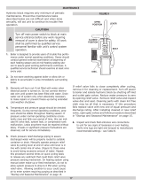
THE FOLLOWING GUIDELINES SHOULD BE FOL
-
LOWED WHEN PIPING THE TANKLESS HEATER:
A. Flow Regulation
If flow through the heater is greater than its rating,
the supply of adequate hot water may not be able to
keep up with the demand. For this reason a FLOW
REGULATOR matching the heater rating should be
installed in the cold water line to the heater. Refer
to Figure
14
for piping recommendations. The flow
regulator should preferably be located below the inlet
to the heater and a minimum of
12
"
away from the
inlet so that the regulator is not subjected to excess
temperatures that may occur during
"
off
"
periods
when it is possible for heat to be conducted back
through the supply line. The flow regulator also limits
the flow of supply water regardless of inlet pressure
variations in the range of
20
to
125
psi.
B.
Tempering of Hot Water
Install a mixing valve at the
tankless heater outlet
to avoid risk of burns or scalding due to excessively
hot water at the fixtures.
Refer to Figure
14
for pip
-
ing recommendations.
Adjust and maintain the mix
-
ing valve in accordance with manufacturers instruc
-
tions.
Installation of a tempering or mixing valve will also
lengthen the delivery of the available hot water by
mixing some cold water with the hot. In addition, sav
-
ings of hot water will be achieved since the user will
not waste as much hot water while seeking water tem
-
peratures to his liking. Higher temperature hot water
Ratings are given
in
gallons per minute
continuous
flow of water heated from
40°F to 140°F with 200°F bol ler water.
TANKLESS
HEATER RATINGS*
required by dishwashers and automatic washers is
possible by piping the hot water from the heater prior
to entering the mixing valve.
The mixing valve should
be
"
trapped
"
by installing it below the cold water
inlet to heater to prevent lime formation in the valve.
BO
I
LER
MODEL
C.
Flushing of Heater
All water contains some sediment which settles on the
inside of the coil.
Consequently, the heater should be
periodically backwashed.
This is accomplished by in
-
stalling hose bibs as illustrated in Figure
14
and al
-
lowing water at city pressure to run into hose bib A,
through the heater, and out hose bib
B
until the dis
-
charge is clear. The tees in which the hose bibs are
located should be the same size as heater connections
to minimize pressure drop.
NUMBER OF
V9
-
2
TANKLESS
HEATERS INSTALLED
D. Hard Water
I
This is applicable to some city water and particularly
to well water.
This should not be a deterent but pre
-
cautions are necessary. A water analysis is necessary
and an appropriate water softener installed. This is
not only beneficial to the heater but to piping and fix
-
tures plus the many other benefits derived from soft
water.
2
TANKLESS
HEATER
3
I
SCHEMATIC
TANKLESS
HEATER
PIPING
3
COLD
WATER
SUPPLV
4
TEMPERED
HIGH TEMP.
HOT WATER
WATER FOR
AUTOMATIC
TO FAUCETS
,
AND SHOWERS
INLET
1
FLO~
R
E
G
U
L
A
T
O
R
IN COLD WATER
RELIEF LINE AT LEAST
3'
FEET
@
-
VALVE
AHEAD
OF TANKLESS
HEATER
Fig.
14
TABLE
I1

@
BOILER PIPING
CONNECT SUPPLY AND RETURN PIPING TO
HEATING SYSTEM.
CAUTION
-
IT IS IMPORTANT THAT THE MINI
-
MUM PIPING REQUIREMENTS AND ARRANGE
-
MENT'S BE COMPLIED WITH IN ORDER TO IN
-
SURE MAXIMUM RELIABILITY PERFORMANCE.
A. CLEARANCES
-
All steam and hot water pipes shall
have clearances of at least
%"
from all combustible
construction.
REAR
OF
BOILER
B.
With STEAM HEATING, see Figure
15,
consult
I=B=R Installation and Piping Guide No.
200.
CAUTION
-
PARTICULAR ATTENTION SHOULD
BE GIVEN TO THE CONSTRUCTION OF THE
HARTFORD LOOP ON STEAM BOILERS. FIGURE
16
ILLUSTRATES THE RIGHT AND WRONG WAY
TO CONSTRUCT THE STEAM HEADER.
V
-
903 AND V
-
904
V
-
905 THRU V
-
907
V
-
911 AND V
-
912
V
-
908 THRU V
-
910
I
BOILER
I
PIPE
SIZE
I
RISER
1
MINIMUM PIPING REQUIREMENTS
STEAM BOILERS
Fig.
15

HORIZONTAL
ON RISERS
AL SECONDARY SUPPLV
USE REDUCING ELBOW
OR ATTACH EQUALIZER
TO BOTTOM
OF HEADER
EQUAL12
ER
CORRECT PHYSICAL ARRANGEMENT FOR STEAM HEADERS
HORIZONTALLY
4
I
TO EQUALIZER
IN
T
FOR STEAM HEADERS
*
Optional Secondary Supply connections illustrated in dotted lines are to be used only in addition to supply connections shown in
solid lines not in lieu of.
Fig.
16

V
-
910
THRU
\
V
-
912
MINIMUM PIPING REQUIREMENTS WATER
BOILERS
Fig.
17
k
C.
With forced circulation HOT WATER HEATING, see
Figure
17, consult I=
B
=
R Installation and Piping
Guide No.
200.
"--REAR
O
F
1.
If this boiler is used in connection with refrigera-
tion systems, the boiler must be installed so that
the chilled medium is piped in parallel with the
heating boiler using appropriate valves to prevent
the chilled medium from entering the boiler, see
Figure
18.
Also, consult
I=B=R
Installation and
Piping Guides.
V
-
908
AND
V
-
909
2.
If this boiler is connected to heating coils located in
air handling units where they may be exposed to
refrigerated air, the boiler piping must be equip-
ped with flow control valves to prevent gravity
circulation of boiler water during the operation of
the cooling system.
3.
If tankless heater is not used and if the boiler is to
be operated in a system which has a large volume
or excessive radiation where low boiler water tem-
peratures may be encountered
(i.e. converted gravi-
ty circulation system, etc.) the use of a boiler water
bypass is recommended to maintain optimum oper
-
ation.
BOILER
S%P$&Y
SpRdzh%
MODEL
RETURN
n,y
1
Y&@'
ARE C
L
OSED
tN
WINTER AND OPEN IN mR
t%kf
AM
OPEN
CI
WMTER AND CLOSED IN SUMMER
WATER
CHILLER
SHUT
-
OFF SHUT
-
OFF
r
VALVE
7
I
HEATING
BOILER
1
[AIR CUSHION TANK
I
SUPPLY MAIN
TO COMBINED
HEATING
8
CIRCULATOR
COOLING
SYSTEM
4
RETURN MAIN
FROM
COMBINED
HEATING
8
COOLING
SYSTEM
RECOMMENDED PIPING FOR COMBINATION
HEATING
&
COOLING (REFRIGERATION) SYSTEMS
WATER BOILERS
Fig.
18

Install a pipe tee between the circulator and boiler
return along with a second tee in the supply piping
as shown in Figure 19. The bypass should be the
same size as the supply and return lines with valves
located in the bypass and supply outlet as illustrated
in Figure 19 in order to regulate water flow for
maintenance of higher boiler water temperature.
Adjust the valves to provide 180°F to 200°F water
temperature when the system water temperature is
at normal operating range.
4.
A hot water boiler installed above radiation level
must be provided with a low water cutoff device
as part of the installation.
@
CANOPY/FLUE OUTLET ASSEMBLY
The parts necessary for items A-C are located in the
canopy carton.
A. Attach the
(2)
canopy mounting brackets to the front
end of the canopy with
(8)
#I0
x
1/2"
hex washer head
sheet metal screws.
TO
SYSTEM
CIRCULATOR
.
DRAIN
COCK
RECOMMENDED BYPASS PIPING
WATER BOILERS
Fig.
19
B.
Along the groove provided on top of the sections and
across the top of the front section, place
2
"
wide cera-
felt strips and overlap at corners. See Figure 20.
GROOVES ON SECTION ASSEMBLAGE FOR CANOPY ATTACHMENT
Fig.
20

C.
Loosely attach the canopy to the lugs on the front of
the section assembly with the
A"
carriage bolts, lock
-
nuts, and washers. See Figure
21.
D.
Open the flue outlet carton.
E.
Attach the
'18"
x
1
"
adhesive fiber gasket to the surface of
the flue outlet assembly that mounts against the back cast
-
ing and canopy.
F.
Secure the flue outlet to the canopy with the
(4)
A"
brass hex nuts and flat washers. Attach the flue out
-
let to the section assembly with the
(4)
&
"
cap screws
and flat washers as shown in Figure
22.
G.
Tighten canopy carriage bolts until canopy is secure.
FLUE OUTLET SECURED AND SEALED
TO CANOPY
AND REAR SECTION
Fig.
22
CLEANOUT COVER
W/
INSULATION
7
/
-
C.I. SECTION
CANOPY SECURED AND SEALED
TO SECTIONS
Fig.
21
@INSTALL FLUE COVER PLATES over cleanout
openings on left side of boiler as shown in Figure
23.
A. Locate the cover plates, carriage bolts, nuts aild wash
-
ers in the 'boiler assembly carton.
B.
Attach the carriage bolts to the top and bottom of the
flue openings with washers and hex nuts to provide
a
fixed stud.
C.
Install flue cover plates over studs with insulation
against boiler and secure with washers and nuts.
CLEANOUT COVER ASSEMBLY
Fig.
23


@
ASSEMBLY OF JACKET
A.
Open jacket carton and jacket hardware package. Un-
less otherwise stated, all jacket components are fasten
-
ed with #8
x
.%
"
hex head sheet metal screws.
Do not
drive sheet metal screws tight until jacket assembly is
complete.
B.
Attach jacket front panel to front section and jacket
back panel to rear section using the (8)
#10
self tap-
ping screws. See Figure
24
for jacket assembly draw-
ing.
C.
Attach each jacket
'J'
channel to one of the jacket 'U'
channels as shown in the jacket detail on the jacket
assembly drawing.
D.
Attach each 'U/J' channel assembly to the bottom of
the front and back panels using
(4)
sheet metal screws.
E.
Attach each remaining 'U' channel to the top of the
front and back panel
('U'
side down) using
(2)
sheet
metal screws.
F.
Attach the jacket top panel to the front panel, back
panel, and upper
'U'
channels.
G.
Fasten the black knobs onto the jacket side panels
using the
#
10
machine screws.
H.
Use Figure
25
to determine the correct positions of the
left side panels.
I.
Install each panel into position by inserting top of pan
-
el into upper
'U'
channel, pushing bottom of panel in
towards boiler, and sliding panel down into
'J'
channel.
J.
Remove the knockouts necessary for tankless heater
operation.
K.
Install the remaining side panels on the right side of
the boiler (order is not important).
L.
Attach the 'D4A' Rating Plate and Water Treatment
Caution Plate (both are in the instructions envelope)
to the front panel using sheet metal screws.
M.
Tighten all sheet metal screws.
V
-
9
JACKET
LEFT
SIDE PANEL ARRANGEMENT
Fig.
25
-C
FRONT
OF
I30
I
LER
60
I
LER
/