Page is loading ...

User Manual
MEGA GO PAR64 PLUS
Rev. 06/15/2023

2
©2023 ADJ Products, LLC all rights reserved. Information, specications, diagrams, images, and
instructions herein are subject to change without notice. ADJ Products, LLC logo and identifying prod-
uct names and numbers herein are trademarks of ADJ Products, LLC. Copyright protection claimed
includes all forms and matters of copyrightable materials and information now allowed by statutory or
judicial law or hereinafter granted. Product names used in this document may be trademarks or regis-
tered trademarks of their respective companies and are hereby acknowledged. All non-ADJ Products,
LLC brands and product names are trademarks or registered trademarks of their respective compa-
nies.
ADJ Products, LLC and all afliated companies hereby disclaim any and all liabilities for property,
equipment, building, and electrical damages, injuries to any persons, and direct or indirect economic
loss associated with the use or reliance of any information contained within this document, and/or as
a result of the improper, unsafe, insufcient and negligent assembly, installation, rigging, and opera-
tion of this product.
Europe Energy Saving Notice
Energy Saving Matters (EuP 2009/125/EC)
Saving electric energy is a key to help protecting the enviroment. Please turn off all electrical products when
they are not in use. To avoid power consumption in idle mode, disconnect all electrical equipment from power
when not in use. Thank you!

3
Unpacking: Thank you for purchasing the Mega Go Par64 Plus by ADJ Products, LLC. Every unit has
been thoroughly tested and has been shipped in perfect operating condition. Carefully check the ship-
ping carton for damage that may have occurred during shipping. If the carton appears to have been
damaged, carefully inspect your xture for any damage and be sure all equipment necessary to oper-
ate the unit has arrived intact. In the event that damage has been found or parts are missing, please
contact our toll free customer support number for further instructions. Please do not return this unit to
your dealer without contacting customer support rst.
Introduction: The ADJ Mega GO Par64 PLUS is a DMX intelligent, high powered LED par xture
which can be used in stand alone mode or connected in a Primary/Secondary conguration. It also
features ve operating modes: Sound Active mode, Auto mode, RGB + UV Dimmer mode, Static Color
mode, and DMX control mode. To optimize the performance of this product, please read these operat-
ing instructions carefully to familiarize yourself with the basic operations of this unit. These instructions
contain important safety information regarding the use and maintenance of this unit. Please keep this
manual with the unit for future reference.
Customer Support: ADJ Products, LLC provides a toll free customer support line, to provide set up
help and to answer any questions should you encounter problems during your set up or initial operation.
You may also visit us on the web at www.adj.com for any comments or suggestions. Service Hours are
Monday through Friday 8:00 a.m. to 4:30 p.m. Pacic Standard Time.
Voice: (323) 582-2650
Fax: (323) 582-2941
To purchase parts online visit parts.adj.com.
Warning! To prevent or reduce the risk of electrical shock or re, do not expose this unit to rain or
moisture.
Caution! There are no user serviceable parts inside this unit. Do not attempt any repairs yourself, as
doing so will void your manufacturer’s warranty. In the unlikely event your unit may require service,
please contact ADJ Products, LLC.
PLEASE recycle the shipping carton when ever possible.
INTRODUCTIONINTRODUCTION

4
• Five Operating Modes
• Electronic Dimming 0-100%
• 5 Selectable Dimming Curves
• 64 Color Macros
• Built in Microphone
• DMX-512 protocol
• 3-Pin DMX Connection
• 5 DMX Modes: 4 Channel Mode, 5 Channel Mode, 6 Channel Mode, 9 Channel Mode, & 10
Channel Mode.
• ADJ LED RC2 & ADJ UC IR, (Not Included)
• Power Cord Daisy Chain (see Power Cord Daisy Chain section of this manual)
The Mega Go Par64 Plus carries a 2 year (730 days) limited warranty. Please fill out the enclosed
warranty card to validate your purchase and warranty. You may also register your product online at
www.adj.com. The R.A. number must be clearly written on the outside of the return package. A brief
description of the problem as well as the R.A. number must also be written down on a piece of paper
included in the shipping carton. If the unit is under warranty, you must provide a copy of your proof of
purchase invoice. You may obtain an R.A. number by contacting our customer support team on our
customer support number. All packages returned to the service department not displaying an R.A.
number on the outside of the package will be returned to the shipper.
WARRANTY REGISTRATION
FEATURES
INSTALLATION
The unit should be mounted using a mounting clamp (not provided), affixing it to the mounting bracket
that is provided with the unit. Always ensure that the unit is firmly fixed to avoid vibration and slipping
during operation. Always ensure that the structure to which you are attaching the unit is secure and
is able to support at least 10 times the unit’s weight. Also, always use a safety cable that can hold 12
times the weight of the unit when installing the fixture.
The equipment must be installed by a professional, and it must be installed in a place where it is out
of the reach of the general public.

5
SAFETY PRECAUTIONS
• To reduce the risk of electrical shock or fire, do not expose this unit to rain or moisture
• Do not spill water or other liquids into or on to your unit.
• Do not attempt to operate this unit if the power cord has been frayed or broken.
• Do not attempt to remove or break off the ground prong from the electrical cord. This prong is
used to reduce the risk of electrical shock and fire in the event of an internal short.
• Disconnect from main power before making any type of connection.
• Do not remove the cover for any reason. There are no user serviceable parts inside.
• Never operate this unit with the cover removed.
• Never plug this unit into a dimmer pack.
• Always be sure to mount this unit in an area that will allow proper ventilation. Allow about 6”
(15cm) between this device and a wall.
• Do not attempt to operate this unit if it has been damaged in any way.
• This unit is intended for indoor use only, and use of this product outdoors voids all warranties.
• During long periods of non-use, disconnect the unit’s main power.
• Always mount this unit in safe and stable matter.
• Power-supply cords should be routed so that they are not likely to be walked on or pinched by
items placed upon or against them, paying particular attention to the point at which they exit from
the unit.
• Cleaning - The fixture should be cleaned only as recommended by the manufacturer. See the
Cleaning section of this manual for cleaning details.
• Heat - The appliance should be situated away from heat sources such as radiators, heat registers,
stoves, or other appliances (including amplifiers) that produce heat.
• The fixture should be serviced by qualified service personnel when:
A. The power supply cord or plug have been damaged.
B. Objects have fallen onto, or liquids have been spilled into, the appliance.
C. The appliance has been exposed to rain or water.
D. The appliance does not appear to operate normally or exhibits a marked change in perfor-
mance.

6
BATTERY PRECAUTIONS
1. Handling of Batteries
1.1 Do Not Short Circuit the Battery
Never short circuit the battery, as doing so generates a very high current which could cause the bat-
tery to overheat, potentially resulting in electrolyte gel leakage, harmful fumes, or explosion. The LIR
tabs can be easily short-circuit when placed on a conductive surface. A short circuit may lead to heat
build up and battery damage. An appropriate circuitry with PCM is employed to protect against acci-
dental short circuit of the battery pack.
1.2 Mechanical shock
Dropping the unit, impacts, bending, etc. may cause failure or shortend life of the LIR battery.
2. Other
2.1 Battery connection
• Direct soldering of wire leads or devices to the battery is strictly prohibited.
• Lead tabs with pre-soldered wiring shall be spot welded to the batteries. Direct soldering may
cause heat buildup, which can damage components, such as the separator and the insulator.
2.2 Prevention of short circuit within a battery pack
There is enough insulation layers between wiring and the batteries to provide extra safety protec-
tion. The battery pack is constructed in such a way as to prevent any short circuit that could result in
smoke or re.
2.3 Do Not Disassemble the Batteries
• Never disassemble the batteries. Doing so may cause an internal short circuit in the battery, which
can result in harmful fumes, re, explosion, or other hazards.
• Electrolyte Gel is harmful! Electrolyte Gel should not leak from the LIR battery. Should the electro-
lyte gel come into contact with the skin or eyes, ush the area of contact immediately with fresh
water and seek medical attention immediately.
2.4 Do Not Expose the Battery to Heat or Fire
Never incinerate or dispose of the batteries in re. Doing so creates a serious explosion risk!
2.5 Do Not Expose the Battery to water or liquids
Never soak/drop the batteries in liquids, including fresh water, seawater, soft drinks, juices, coffee or
other beverages.
2.6 Battery Replacement
For battery replacement please contact ADJ customer support (323) 582-2650.
2.7 Do Not use a damaged Battery
Inspect the battery for damage that may have occurred during shipping. In the event that damage is
present, including but not limited to damage to the plastic casing of the battery, deformation of the
battery package, the presence of an electrolyte odor, or leakage of the electrolyte gel, DO NOT use
the battery. A battery with a odor of electrolyte or a gel leakage should be placed away from re to
avoid re or explosion.

7
3. Battery Storage
Store the battery at room temperature, with a charge of at least 50%. During long periods of storage,
it is recommended to charge the battery every 6 months. Doing so will prolong the life of the battery,
and will also ensure that the battery is ready for use.
4. Other Chemical Reactions
Because batteries utilize a chemical reaction, battery performance will deteriorate over time, even if
stored for a long period of time without being used. Additionally, if the various usage conditions such
as charge, discharge, ambient temperature, etc. are not maintained within the specied ranges, the
life expectancy of the battery may be shortened, or the device in which the battery is used may be
damaged by electrolyte gel leakage. If the batteries cannot maintain a charge for long periods of time,
even when they are charged correctly, this may indicate it is time to change the battery.
5. Battery Disposal
Please dispose of battery according to local regulations.
BATTERY PRECAUTIONS

8
DMX SETUP
Power Supply: The ADJ Mega GO Par64 PLUS contains an automatic voltage switch, which will
automatically sense the voltage when it is plugged into the power source. With this switch there is no
need to worry about the correct power voltage, and this unit can be plugged in anywhere.
DMX-512: DMX is short for Digital Multiplex. This is a universal protocol used as a form of communi-
cation between intelligent xtures and controllers. A DMX controller sends DMX data instructions from
the controller to the xture. DMX data is sent as serial data that travels from xture to xture via the
DATA “IN” and DATA “OUT” XLR terminals located on all DMX xtures (most controllers only have a
DATA “OUT” terminal).
DMX Linking: DMX is a language allowing all makes and models of different manufacturers to be
linked together and operate from a single controller, as long as all xtures and the controller are
DMX compliant. To ensure proper DMX data transmission, try to use the shortest cable path possible
when linking several DMX xtures. The order in which xtures are connected in a DMX line does not
inuence the DMX addressing. For example, a xture assigned a DMX address of 1 may be placed
anywhere in a DMX line: at the beginning, at the end, or anywhere in the middle. When a xture is
assigned a DMX address of 1, the DMX controller knows to send DATA assigned to address 1 to that
unit, no matter where it is located in the DMX chain.
Data Cable (DMX Cable) Requirements (For DMX Operation): The Mega GO Par64 PLUS can
be controlled via DMX-512 protocol, and features 5 selectable DMX modes, as detailed in the DMX
Traits section of this manual. The DMX address is set on the back panel of the Mega GO Par64
PLUS. Your unit and your DMX controller require a standard 3-pin XLR connector for data input and
data output (Figure 1). We recommend Accu-Cable DMX cables. If you are making your own cables,
be sure to use standard 110-120 Ohm shielded cable (This cable may be purchased at almost all pro
lighting stores). Your cables should be made with a male XLR connector at one end and a female
XLR connector at the other. Also remember that DMX cable must be daisy chained and cannot be
split.
Figure 1

9
DMX SETUP
Notice: Be sure to follow gures two and three when making your own cables. Do not use the ground
lug on the XLR connector. Do not connect the cable’s shield conductor to the ground lug or allow the
shield conductor to come into contact with the XLR’s outer casing. Grounding the shield could cause
a short circuit and erratic behavior.
Special Note: Line Termination. When longer runs of cable are used, you may need to use a termi-
nator on the last unit to avoid erratic behavior. A terminator is a 110-120 ohm 1/4 watt resistor which is
connected between pins 2 and 3 of a male XLR connector (DATA + and DATA -). This unit is inserted
in the female XLR connector of the last unit in your daisy chain to terminate the line. Using a cable
terminator (ADJ part number Z-DMX/T) will decrease the possibilities of erratic behavior.
5-Pin XLR DMX Connectors. Some manufacturers use 5-pin DMX-512 data cables for DATA trans-
mission in place of 3-pin. 5-pin DMX xtures may be implemented in a 3-pin DMX line by inserting an
adapter into the line. These adapters are readily available at most electronics stores. The chart below
details a proper cable conversion.
Conductor 5-Pin XLR Male (In)3-Pin XLR Female (Out)
Pin 1
Do Not Use
Do Not Use
Pin 3
Pin 2
Pin 1
Pin 3
Pin 2
Not Used
Not Used
Data True (+ signal)
Data Compliment (- signal)
Ground/Shield
3-Pin XLR to 5-Pin XLR Conversion
DMX512 IN
3-PIN XLR
1
2
3
1
2
3
DMX +
DMX -
COMMON
3-PIN XLR
Figure 2
Figure 3
1 Ground 1 Ground
XLR Male Socket
3 Hot
2 Cold 2 Cold
3 Hot
XLR Female Socket
Pin 3 = Data True (positive)
Pin 2 = Data Compliment (negative)
Pin 1 = Ground
1
2
3
Termination reduces signal errors and
avoids signal transmission problems
and interference. It is always advisable
to connect a DMX terminal, (Resistance
120 Ohm 1/4 W) between PIN 2 (DMX-)
and PIN 3 (DMX +) of the last fixture.Figure 4

10
System Menu: The display will lock after 30 seconds.To unlock, press and the MODE button
for 3 seconds.
LED Display On/Off:
To set the display press the MODE button until “dXX” is displayed. Use the UP or DOWN buttons to
select either:
• “don” = LED display on at all times.
• “doFF” = LED display shuts off after 10 seconds.
Please note, the display will turn off automatically after 10 seconds.
LED Display Inversion:
Follow these instructions to ip the display 180° so that the display can be read upside down.
1. Plug the xture in and press the MODE button until “dXX” is displayed. “XX” represents either “on”
or “oFF”.
2. Press the SET UP button until “Stnd” is displayed.
3. Press the UP or DOWN buttons to reverse the display 180°.
Operating Modes:
The Mega GO Par64 PLUS has ve selectable operating modes:
• RGB+UV Dimmer Mode - Choose one of the four colors to remain static, or adjust the intensity of
each color to make a custom color.
• Sound-Active mode - The unit will react to sound, chasing through the built in programs. There are
16 sound active modes.
• Auto Run Mode - In Auto Run mode, you can choose 1 of 16 color change modes, 1 of 16 color
fade modes, or a combo color change & fade mode.
• Static Color Mode - There are 64 colors to choose from.
• DMX control mode - This function will allow you to control each individual xtures traits with a
standard DMX 512 controller.
RGB+UV Dimmer Mode:
1. Plug the xture in and press the MODE button until the desired option is shown:
• When “r.XXX” is displayed, the unit is in Red dimming mode. Press the UP and DOWN buttons
to adjust intensity.
• When “G.XXX” is displayed, the unit is in Green dimming mode. Press the UP and DOWN but-
tons to adjust intensity.
• When “b.XXX” is displayed, the unit is in Blue dimming mode. Press the UP and DOWN buttons
to adjust intensity.
• When “u.XXX” is displayed, the unit is in UV dimming mode. Press the UP and DOWN buttons
to adjust intensity.
2. After you have adjusted the RGB & UV colors to create your desired color, you can then activate
strobing by pressing the SET UP button to enter the Flash (strobe) mode.
3. “FS.XX” will be displayed, indicating that the unit is in Flash mode. The Flash can be adjusted
between “FS.00” (ash off) to “FS.15” (fastest ash).
OPERATING INSTRUCTIONS

11
Sound Active Mode:
In this mode, the unit will react to sound and chase through the different colors.
1. Plug the xture in and press the MODE button until “SoXX” is displayed. “XX” represents the cur-
rent sound active mode (1-16).
2. Use the UP or DOWN buttons to nd your desired sound active mode.
3. Press the SET UP button to enter sound sensitivity adjustment. “SJ-X” will be displayed. Use the
UP or DOWN buttons to adjust the sensitivity. “SJ-1” is the lowest sensitivity, “SJ-8” is the highest.
Auto Run Mode:
There are 3 types of Auto Run Modes to choose from: Color Fade, Color Change, and both modes
running together. The running speed is adjustable in all 3 modes.
1. Plug the xture in and press the MODE button until either “AFXX”, “AJXX”, or “A-JF” is displayed.
• AFXX = Color Fade mode. There are 16 Color Fade modes to choose from. Use the UP or
DOWNbuttons to scroll through the different Auto Fade modes.
• AJXX = Color Change mode. There are 16 Color Change modes to choose from. Use the UP or
DOWN buttons to scroll through the different Auto Change modes.
• A-JF = Both Color Fade and Color Change modes running.
2. After you have chosen your desired running mode, press the SET UP button until “SP.XX” is
displayed. You can now adjust the running speed of your desired program. Use the UP or DOWN
button to adjust the speed between “SP.01” (slowest) and “SP.16” (fastest). Press the SET UP but-
ton to return to your desired Auto Run Mode.
Static Color Mode:
1. Plug the xture in and press the MODE button until “CLXX” is displayed.
2. There are 64 colors to choose from. Select your desired color by pressing the UP and DOWN but-
tons.
3. After you have selected your desired color, you can activate strobing by pressing the SET UP but-
ton to enter the Flash (strobe) mode. “FS.XX” will be displayed, indicating that the unit is in Flash
mode. The Flash can be adjusted between “FS.00” (ash off) to “FS.15” (fastest ash).
DMX Mode:
Operating through a DMX controller gives the user the freedom to create custom programs tailored
to his or her own individual needs. This function also allows you to use your xtures as spot lights.
The Mega GO Par64 PLUS has 5 DMX modes: 4 channel mode, 5 channel mode, 6 channel mode, 9
channel mode, and a 10 channel mode. See the DMX Traits section of this manual for detailed infor-
mation.
1. To run your xture in DMX mode, press the MODE button until “d.XXX” is displayed. “XXX” repre-
sents the currently selected DMX address. Use the UP or DOWN buttons to select your desired
DMX address, then press the SETUP button to select your DMX Channel mode.
2. Use the UP or DOWN buttons to scroll through the DMX Channel modes. The available channel
modes are 4-Channel Mode (Ch04), 5-Channel Mode (Ch05), 6-Channel Mode (Ch06), 9-Channel
Mode (Ch09), or 10-Channel Mode (Ch10).
3. After you have chosen your desired DMX Channel mode, plug in the xture via the XLR connec-
tions to any standard DMX controller.
OPERATING INSTRUCTIONS

12
OPERATING INSTRUCTIONS
DMX State:
This mode determines how the unit will behave when the DMX signal is lost or interrupted. It can also
be used to select the operating mode that the unit will default to when powered on.
1. Plug the xture in and press the MODE button until “d.XXX” is displayed. “XXX” represents the
currently selected DMX address.
2. Press the SET UP button so that “nodn” is displayed. Use the UP and DOWN buttons to scroll
through the DMX states.
• “bLAC” (Blackout) - If the DMX signal is lost or interrupted, the unit will automatically go into
stand by mode.
• “LASt” (Last State) - If the DMX signal is lost or interrupted, the xture will stay in the last DMX
set up.
• “ProG” (Auto Run) - If the DMX signal is lost or interrupted, the unit will automatically go into
Auto Run mode.
3. Press SET UP to select the option displayed and exit.
Dimmer Curve:
This is used to set the dimming curve used with DMX mode. See the Dimming Curves section of this
manual for detailed information.
1. Plug the xture in and press the MODE button until “DMX MODE” is displayed.
2. Press the SET UP button until “dr-X” is displayed, where “X” represents the displayed dimmer
curve (0-4).
• 0 - Standard
• 1 - Stage
• 2 - TV
• 3 - Architectural
• 4 - Theatre
3. Press the UP or DOWN buttons to scroll through and select the desired dimming curve.
Activate IR Sensor:
This function is used to activate and deactivate the IR sensor. When this function is activated, you
can control the xture using the ADJ LED RC2 or UC IR. Please refer to the ADJ LED RC2 Control
and UC IR Control sections of this manual for detailed information.
1. Plug the xture in and press the MODE button until “dXX” is displayed. “XX” represents either “on”
or “oFF”.
2. Press the SET UP button until “IrXX” is displayed. “XX” represents either “on” or “oF”.
3. Press the UP or DOWN buttons to either activate the remote function (On) or deactivate it (Off).
Default Running Mode:
When this function is activated, all modes will return to their default settings.
1. Plug the xture in and press the MODE button until “dXX” is displayed. “XX” represents either “on”
or “oFF”.
2. Press the SET UP button until “dEFA” is displayed.
3. Press the UP and DOWN buttons simultaneously. Press the MODE button to exit.

13
PRIMARY-SECONDARY CONFIGURATION
This function will allows you to link units together to run in a Primary-Secondary set-up, in which one
unit will act as the controlling unit and the others will react to the controlling unit’s built-in programs.
Any unit can act as a primary or as a secondary, but in a given system, only one unit can be pro-
grammed to act as the “primary.”
Primary-Secondary Connections and Settings:
Daisy chain your units via the XLR connectors on the rear panel of each unit. Use standard XLR data
cables to link your units together. Remember that the male XLR connector is the input, and the fe-
male XLR connector is the ouput. The rst unit in the chain (primary) will use the female XLR connec-
tor only, while the last unit in the chain will use the male XLR connector only.
Connect the rst “secondary” unit to the “primary.”
Set the “primary” unit to your desired mode of operation, then set the “secondary” unit(s) to the DMX
address setting of 001.The “secondary” unit(s) will now follow the “primary”.
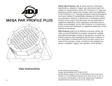
CAD DRAWING
247mm/9.72”
262.14mm/10.32”
210mm/8.26”
195.64mm/7.70”
111.74mm/4.39”

14
ADJ LED RC2 OPERATION
The ADJ LED RC2 infrared remote (sold seperately) has many different functions and provides com-
plete control of this xture. The controller must be aimed at the front of the xture, and the xture’s
infrared sensor must be switched on, as described in the Operating Instructions section of this
manual. Maximum range is 30 feet. Please note that the xture will only respond to the remote when
the xture is set to Secondary mode.
BLACKOUT - Pressing this button will blackout the xture.
PROGRAM SELECTION - This button will let you access color change mode, color fade mode, auto
run mode, or static color mode. Each press of this button will scroll change to the next mode. Once
you have selected your desired mode, use the “+” or “-” to scroll through the programs or static colors.
When using the auto run, color fade, or color change, press the Speed button and use the “+” or “-” to
adjust the running speed.
• If the Red LEDs ash, the xture is in Color Fade Mode.
• If the Green LEDs ash, the xture is in Color Change Mode.
• If the Blue LEDs ash, the xture is in Auto Run Mode.
• If the UV LED ashes, the xture is in Static Color Mode.
FLASH - This button will activate the strobe effect. You can control the ash rate by pressing the “+”
and “-” buttons. Press this button again to exit strobe mode.
SPEED - Press this button, then use the “+” & “-” buttons to adjust the speed of the auto run, color
change, and color fade, or adjust the sound sensitivity in sound active mode.
DMX MODE - Pressing his button will scroll through DMX addressing, DMX Channel mode, DMX last
state setting, and dimmer curve mode. Some xtures will come with different DMX channel modes.
When your desired menu/submenu is found, use the “+” & “-” buttons to scroll through the settings.
See the Operating Instructions and DMX Traits sections of this manual for detailed information.
SECONDARY/SA (SOUND ACTIVE) - Use this button to toggle between sound active mode and sec-
ondary mode. In sound active mode, use the “+” and “-” buttons to scroll through the 16 sound active
programs. Press the Speed button to and use the “+” and “-” buttons to adjust the sound sensitivity.
SET ADDRESS - Press this button to set the DMX address. Press this button rst, then press the
numbers to set the address.
Example: To set DMX Address = 1, press “SET ADDRESS”, then key in “0-0-1”. Alternately, to set
DMX Address = 245, press “SET ADDRESS”, then key in “2-4-5”.
R G B A - Press any one of these buttons to select a color, then press the “+” or “-” to adjust the
brightness. “A” selects UV dimmer mode.
“+” and “-” - Use these buttons to adjust the ash rate, speed of the built-in programs, sound sensi-
tivity, and program selection.

15
ADJ LED RC2 CONTROL
DMX Control:
Operating through an DMX controller gives the user the freedom to create custom programs tailored
to his or her own individual needs. Follow the directions below to set your DMX channel mode and
ad-dress.
1. Before connecting to an DMX controller, please select your desired DMX channel mode by press-
ing the DMX Mode button, then using the “+” or “-” buttons to scroll through the available options.
Set the mode before you address the xture.
2. Set the DMX address for the xture by pressing the “S” button. The LEDs will ash 2-3 times, then
all the red LEDs will light. Use the number buttons to press in your desired address. Please note:
When setting the DMX address, an LED color will glow each time a number is pressed, then all
LEDs will ash 2-3 times when you have successfully set the DMX address.
3. Now you may connect the xture via the XLR connections to any standard DMX controller.
• If All LEDs ash, the xture is in DMX Mode 1: 4 DMX Channel.
• If the Red LEDs ash, the xture is in DMX Mode 2: 5 DMX Channels.
• If the Green LEDs ash, the xture is in DMX Mode 3: 6 DMX Channels.
• If the Blue LEDs ash, the xture is in DMX Mode 4: 9 DMX Channels.
• If the UV LED ashes, the xture is in DMX Mode 5: 10 DMX Channels.

16
UC IR REMOTE CONTROL
The UC-IR infrared remote gives you control of various functions. To control the xture you must aim
the remote at the front of the xture, and the xture’s infrared sensor must be switched on, as de-
scribed in the Operation Instructions section of this manual. Maximum range is 30 feet. Please note
that the xture only responds to the remote when the xture is set to primary mode.
STAND BY - Pressing this button will blackout the xture. Press this button again to return to original
state.
FULL ON - Press and hold to fully illuminate the unit. The unit will return to its previous state when
the button is released.
FADE/GOBO - Activates color fade mode.
“DIMMER +” and “DIMMER -” - Adjust the color output intensity in static color mode.
STROBE - Press and hold to activate the strobe effect.
COLOR - Press this button to activate color control. Use buttons 1-9 to select your desired color.
1-9 - These buttons will allow you to select either a particular show option or color option, depending
on which operating mode the xture is in.
SOUND ON & OFF - These buttons activate and deactivate the sound active mode.
SHOW 0 - This activates the show mode. Use buttons 1-9 to select your desired show. Press the
Show 0 button twice to run show 10, and button 1 twice to run show 11.

17
DMX TRAITS
CHANNEL DMX VALUES FUNCTION
4CH 5CH 6CH 9CH 10CH
1 1 1 1 1 000 - 255 Red, 0% to 100%
2 2 2 2 2 000 - 255 Green, 0% to 100%
3 3 3 3 3 000 - 255 Blue, 0% to 100%
4 4 4 4 4 000 - 255 UV, 0% to 100%
5 5 5
Shutter/Strobe
000 - 031 LED Off
032 - 063 LED On
064 - 095 Strobing, slow to fast
096 - 127 LED On
128 - 159 Strobe Pulse, slow to fast
160 - 191 LED On
192 - 223 Random Strobe, slow to fast
224 - 255 LED On
5 6 6 6 000 - 255 Master Dimmer, 0% to 100%
7 7
Program Selection Mode
000 - 051 Dimming Mode
052 - 102 Color Macro Mode
103 - 153 Color Change Mode
154 - 204 Color Fade Mode
205 - 255 Sound Active Mode
8 8
000 - 255 Color Macro Mode, see Color Macro Chart sec-
tion of this manual for details
Color Change Programs
000 - 015 Color Change 1
016 - 031 Color Change 2
032 - 047 Color Change 3
048 - 063 Color Change 4
064 - 079 Color Change 5
080 - 095 Color Change 6
096 - 111 Color Change 7
112 - 127 Color Change 8
128 - 143 Color Change 9
144 - 159 Color Change 10
160 - 175 Color Change 11
176 - 191 Color Change 12
192 - 207 Color Change 13
CONTINUED ON NEXT PAGE

18
DMX TRAITS
CHANNEL DMX VALUES FUNCTION
4CH 5CH 6CH 9CH 10CH
8 8
Color Change Programs (continued)
208 - 223 Color Change 14
224 - 239 Color Change 15
240 - 255 Color Change 16
Color Fade Programs
000 - 015 Color Fade 1
016 - 031 Color Fade 2
032 - 047 Color Fade 3
048 - 063 Color Fade 4
064 - 079 Color Fade 5
080 - 095 Color Fade 6
096 - 111 Color Fade 7
112 - 127 Color Fade 8
128 - 143 Color Fade 9
144 - 159 Color Fade 10
160 - 175 Color Fade 11
176 - 191 Color Fade 12
192 - 207 Color Fade 13
208 - 223 Color Fade 14
224 - 239 Color Fade 15
240 - 255 Color Fade 16
Sound Active Programs
000 - 015 Sound Active Mode 1
016 - 031 Sound Active Mode 2
032 - 047 Sound Active Mode 3
048 - 063 Sound Active Mode 4
064 - 079 Sound Active Mode 5
080 - 095 Sound Active Mode 6
096 - 111 Sound Active Mode 7
112 - 127 Sound Active Mode 8
128 - 143 Sound Active Mode 9
144 - 159 Sound Active Mode 10
160 - 175 Sound Active Mode 11
176 - 191 Sound Active Mode 12
192 - 207 Sound Active Mode 13
208 - 223 Sound Active Mode 14
CONTINUED ON NEXT PAGE

19
DMX TRAITS
CHANNEL DMX VALUES FUNCTION
4CH 5CH 6CH 9CH 10CH
8 8
Sound Active Programs (continued)
224 - 239 Sound Active Mode 15
240 - 255 Sound Active Mode 16
9 9
000 - 255 Program Speed, slow to fast
Sound Sensitivity
000 - 031 Off
032 - 255 Least Sensitivie to Most Sensitive
10
Dimmer Curves
000 - 020 Standard
021 - 040 Stage
041 - 060 TV
061 - 080 Architectural
081 - 100 Theatre
101 - 255 Default to Unit Setting
NOTE FOR 9CH MODE AND 10CH MODE:
• When Channel 7 is between the values of 0-51, Channels 1-4 are used, and Channel 5 will control
strobing.
• When Channel 7 is between the values of 52-102, Channel 8 is in Color Macros Mode, and Chan-
nel 5 will control strobing.
• When Channel 7 is between the values of 103-153, Channel 8 is in Color Change Mode, and
Channel 9 will control the color change speed.
• When Channel 7 is between the values of 154-204, Channel 8 is in Color Fade Mode, and Chan-
nel 9 will control the color fade speed.
• When Channel 7 is between the values of 205-255, Channel 8 is in Sound Active Mode, and
Channel 9 will control the sound sensitivity.

20
COLOR MACROS CHART
COLOR NO. DMX VALUE COLOR INTENSITY
RED GREEN BLUE UV
Color 0 000 0 0 0 0
Color 1 001 - 004 80 255 234 80
Color 2 005 - 008 80 255 164 80
Color 3 009 - 012 77 255 112 77
Color 4 013 - 016 117 255 83 83
Color 5 017 - 020 160 255 77 77
Color 6 021 - 024 223 255 83 83
Color 7 025 - 028 255 243 77 77
Color 8 029 - 032 255 200 74 74
Color 9 033 - 036 255 166 77 77
Color 10 037 - 040 255 125 74 74
Color 11 041 - 044 255 97 77 74
Color 12 045 - 048 255 71 77 71
Color 13 049 - 052 255 83 134 83
Color 14 053 - 056 255 93 182 93
Color 15 057 - 060 255 96 236 96
Color 16 061 - 064 238 93 255 93
Color 17 065 - 068 196 87 255 87
Color 18 069 - 072 150 90 255 90
Color 19 073 - 076 100 77 255 77
Color 20 077 - 080 77 100 255 77
Color 21 081 - 084 67 148 255 67
Color 22 085 - 088 77 195 255 77
Color 23 089 - 092 77 234 255 77
Color 24 093 - 096 158 255 144 144
Color 25 097 - 100 255 251 153 153
Color 26 101 - 104 255 175 147 147
Color 27 105 - 108 255 138 186 138
Color 28 109 - 112 255 147 251 147
Color 29 113 - 116 151 138 255 138
Color 30 117 - 120 151 138 255 138
Color 31 121 - 124 138 169 255 138
Color 32 125 - 128 255 255 255 255
Color 33 129 - 132 255 206 143 0
Color 34 133 - 136 254 177 153 0
Color 35 137 - 140 254 192 138 0
Color 36 141 - 144 254 165 98 0
CONTINUED ON NEXT PAGE
/