
240223-7
2H
Installation and Operation Manual
H8D-UC / H8D-FS- U C /
H10D / H10D-FS
Series
H o t H o l d i n g C a b i n e t s
(Digital Operation)

The reproduction or copying of any part of this manual by any means whatsoever is strictly forbidden unless authorized previously in writing
by the manufacturer.
In line with policy to continually develop and improve its products, Moffat Ltd. reserves the right to change the specifications and design
without prior notice.
© Copyright Moffat Ltd. June 2019.
Moffat Limited
Rolleston 7675
New Zealand
AUSTRALIA
Moffat Pty Limited
Web: www.moffat.com.au
E.Mail: vsales@moffat.com.au
Main Office: (tel) +61 (03) 9518 3888
(fax) +61 (03) 9518 3838
Service: (tel): 1800 622 216
Spares: (tel): 1800 337 963
Customer Service: (tel): 1800 335 315
(fax): 1800 350 281
CANADA
Serve Canada
Web: www.servecanada.com
E.Mail: info@servecanada.com
Sales: (tel): 800 551 8795 (Toll Free)
Service: (tel): 800 263 1455 (Toll Free)
NEW ZEALAND
Moffat Limited
Web: www.moffat.co.nz
E.Mail: sales@moffat.co.nz
Main Office: (tel): 0800 663328
UNITED KINGDOM
Blue Seal
Web: www.blue-seal.co.uk
E.Mail: sales@blue-seal.co.uk
Sales: (tel): +44 121 327 5575
(fax): +44 121 327 9711
Spares: (tel): +44 121 322 6640
(fax): +44 121 327 9201
Service: (tel): +44 121 322 6644
(fax): +44 121 327 6257
UNITED STATES
Moffat
Web: www.moffat.com
Sales: (tel): 1-800 551 8795 (Toll Free)
(tel): 336 661 1556
(fax): 336 661 9546
Service: (tel): 866 673 7937 (Toll Free)
REST OF WORLD
Moffat Limited
Web: www.moffat.co.nz
E.Mail: e[email protected]

Contents List
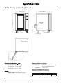
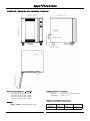
H8D-UC / H8D-FS-UC / H10D / H10D-FS Series
H8D-UC - Turbofan Hot Holding Cabinet - Under Counter, 8 x 1/1 GN / 8 x US Half Size Trays.
H8D-FS-UC - Turbofan Hot Holding Cabinet - Under Counter, 8 x US Full Size Trays.
H10D - Turbofan Hot Holding Cabinet - 10 x 1/1 GN / 10 x US Half Size Trays.
H10D-FS - Turbofan Hot Holding Cabinet - 10 x US Full Size Trays.
Safety Information
Installation Requirements
Unpacking
Location
Clearances
Electrical Connection
Positioning the Holding Cabinet
Initial Start-Up
Technical Data Plate Location
Operation Guide
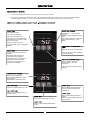
Digital Hot Holding Cabinet Control Panel - Description of Controls
Using the Hot Holding Cabinet
Setting the Operator Accessible Parameters
Controller Parameters and Default Settings
Cleaning Guidelines
Periodic Maintenance

Introduction
2
Before using your new Holding Cabinet, please read this instruction
manual carefully, pay particular attention to any information labelled
‘WARNING’, ‘CAUTION’, ‘IMPORTANT’ or ‘NOTE’ in this manual.
Indicates a hazardous situation
which, if not avoided, will result in
death or serious injury.
Indicates a hazardous situation
which, if not avoided, will result in
minor or moderate injury.
If you are unsure of any aspect of installation, instructions or
performance of your Holding Cabinet, contact your TURBOFAN dealer
promptly. In many cases a phone call could answer your question.
Should you contact your TURBOFAN dealer on any matter concerning
this Holding Cabinet, please have the information provided opposite,
readily available.
This manual must be kept by the owner for future reference.
A record of
Date of Purchase,
Date of Installation
and
Serial
Number of Holding Cabinet
should be recorded in area provid-
ed below.
The serial number of this Holding Cabinet can be found on the
Technical Data Plate located on front right hand side panel, see
diagram in ‘Installation Section’.
For your safety, please pay attention to the following symbols
marked on the appliance.
- Risk of electric shock.
No user serviceable parts inside.
Qualified service person access only.
Disconnect from power before servicing.

Specifications
3
230V-240V, 50HZ, 1P+N+E, 2.05kW.
208V-240V, 60HZ, 1P+N+E, 2.05kW
220V-240V, 50HZ, 1P+N+E, 2.05kW
220V-240V, 60HZ, 1P+N+E, 2.05 kW
81kgs (179lbs) (Ex cluding Baking Trays).
Tray Size; Qty 8, 18” x 26” US Full Size Pans.
Tray Spacing 74mm / 27/8”.
Rear L/H Side R/H Side
H8D-FS-UC 25mm / 1” 0mm / 0” 0mm / 0”

Specifications
4
230V-240V, 50HZ, 1P+N+E, 1.3kW.
110V-120V, 60HZ, 1P+N+E, 1.3kW
220V-240V, 50HZ, 1P+N+E, 1.3kW
220V-240V, 60HZ, 1P+N+E, 1.3kW
65kgs (143lbs) (Ex cluding Baking Trays).
Tray Size; Qty 8, 12” x 20” 1/1 GN Steam Pans.
Qty 8, US Half Size Sheet Pans.
Tray Spacing 74mm / 27/8”.
Rear L/H Side R/H Side
H8D-UC 25mm / 1” 0mm / 0” 0mm / 0”

Specifications
5
230V-240V, 50HZ, 1P+N+E, 1.3kW.
110V-120V, 60HZ, 1P+N+E, 1.3kW
220V-240V, 50HZ, 1P+N+E, 1.3kW
220V-240V, 60HZ, 1P+N+E, 1.3kW
77.5kgs (171lbs) (Ex cluding Baking Trays).
Tray Size; Qty 10, 12” x 20” 1/1 GN Steam Pans.
Qty 10, US Half Size Sheet Pans.
Tray Spacing 74mm / 27/8”.
Rear L/H Side R/H Side
H10D 25mm / 1” 0mm / 0” 0mm / 0”

Specifications
6
230V-240V, 50HZ, 1P+N+E, 2.05kW.
208V-240V, 60HZ, 1P+N+E, 2.05kW.
220V-240V, 50HZ, 1P+N+E, 2.05kW.
220V-240V, 60HZ, 1P+N+E, 2.05kW.
88kgs (194lbs) (Excluding Bak ing Trays).
Tray Size; Qty 10, 18” x 26” US Full Size Pans.
Tray Spacing 74mm / 27/8”.
Rear L/H Side R/H Side
H10D-FS 25mm / 1” 0mm / 0” 0mm / 0”

Installation
7
• Remove all packing.
• Check equipment and parts for damage. Report any damage
immediately to the carrier and distributor.
• Remove protective plastic coating from side panels.
• Check that the following parts have been supplied with your
Holding Cabinet:
Side Racks.
Condensation Collection Pan.
Report any deficiencies to distributor who supplied Holding
Cabinet.
Check available power supply is correct to as shown on Rating
Plate located on front lower corner of right hand side panel.
Refer to ‘Technical Data’ in ‘Specifications’ section.
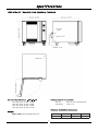
Position the Hot Holding Cabinet in its working position.
The Hot Holding Cabinet should be positioned so that operating
panel and cabinet shelves can be easily reached for loading and
unloading.
To ensure correct ventilation for motor and controls, the
following minimum installation clearances are to be adhered to:
Clearance From Source of Heat.
Where the appliance is located next to a source of heat, a
minimum distance of 300mm (12”) from the appliance sides
is required.
Each Hot Holding Cabinet should be connected to an adequately
protected power supply with an appropriate power cord.
RCD (Residual Current Device) / GFCI (Ground-Fault Circuit-
Interrupter) protection of the power supply to this appliance is rec-
ommended.
An isolation switch mounted adjacent to, but not behind the Hot
Holding Cabinet and must be readily accessible to the operator.
This switch must be clearly marked and readily accessible in case of
fire.
Check that the electricity supply is correct to as shown on the
Technical Data Plate on the front right hand corner of the holding
cabinet side panel.
The Hot Holding Cabinets are supplied with electrical cords fitted.
Ensure that the appliance is fitted with the appropriate power cord
and plug.
Correctly locate the Hot Holding Cabinet into its final operating
position and lock the front castors to retain the holding cabinet in
it’s location.
Before using the new Hot Holding Cabinet;
1. Please refer to Operation Section of this manual for details on
how to correctly operate and shutdown the Holding Cabinet.
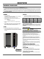
Technical Data Plate for the Holding Cabinets is located at bottom
left corner of RH side panel.
Installation shall comply with local electrical, health and safety requirements.
It is most important that this Holding Cabinet is installed correctly and that Holding Cabinet operation is correct before
use.
If you have any questions regarding proper installation and / or operation of this Holding Cabinet, please contact your
local Turbofan distributor.
This Holding Cabinet must be earthed / grounded.
If the supply cord is damaged, it must be replaced by a
suitably qualified person in order to avoid a hazard.
H8D-UC H8D-FS-UC H10D H10D-FS
Rear 25mm / 1” 25mm / 1” 25mm / 1” 25mm / 1”
L/H Side 0mm / 0” 0mm / 0” 0mm / 0” 0mm / 0”
R/H Side 0mm / 0” 0mm / 0” 0mm / 0” 0mm / 0”
Technical Data Plate
Location

Operation
8
Turbofan Hot Holding Cabinets have been designed to provide simple operation.
This Hot Holding Cabinet is intended for use in a commercial kitchen and must only be put to the use for which it was intended,
i.e. Holding of food products. To use this Hot Holding Cabinet correctly, please read the following sections carefully:-
Timer LEDs are ‘Off’ when timer not
running.
Timer LEDs ‘Flash’ when timer is
running and time is displayed.
If more than 1 timer is running, only
displayed time timer LED flashes.
Timer LED is ‘On’ when a timer is
running but not displayed.
Shows Set Hold Temperature.
Shows Actual Temperature if ‘Temp’
Key is pressed.
Display flashes when setting Temp.
Used to turn Holding Cabinet ‘On / Off’.
LED is ‘On’ when Holding Cabinet is in
‘Stand-By’ mode.
Press to display Actual Temperature.
Hold for 2 seconds to change ‘Set
Temperature’.
LED is ‘On’ when Holding Cabinet is
heating.
LED is ‘Off’ when Holding Cabinet is at
set temperature.
Used to ‘Change / Set’ timers.
Used to ‘Change / Set’ hold
temperature.
* After 2 seconds, hold down Timer or
Temp Key.
Timers can be set for count down time,
or,
Timers can be set for
‘INF’
, indefinitely
count up hold timing.
Three Separate Timers.
Press to start pre-set timer.
Press and hold to cancel timer.
Three timers can run simultaneously.
Press timer key to show time, if more
than 1 timer running.
Hold for 2 seconds to set time.
Use Up/Down/Set keys to change timer
settings.
Press to turn Cabinet lights ‘On / Off’.
LED is ‘On’ when Holding Cabinet lights
are ‘On’.
Timer display “----” when no timer
running.
Timer(s) running - displays time count
down.
Least remaining time shown as default.
If timer time is being set - ‘Time’
flashes.

Operation
9
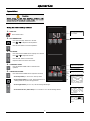
1. TURN ‘ON’.
Press ‘On-Off’ button.
2. SET TEMPERATURE.
Press and hold ‘Temp’ button for 2 seconds.
Press or to adjust the set temperature.
Press the ‘SET’ button to set the temperature.
3. SET TIMERS.
Press and hold the ‘TIMER’ button required, for 2 seconds.
Press or to adjust the set time.
Press the ‘SET’ button to set the timer.
Repeat the actions to set the other timers.
4. STARTING A TIMER.
Press the desired ‘TIMER’ button to start the timer
operation.
5. CANCELLING A TIMER.
Press and hold the ‘TIMER’ button required to cancel the timer.
- Press any button, to cancel the ‘Time Up’ alarm.
- Press ‘Temp’ button, to check ‘Actual’ temperature of hot
holding cabinet at any time during operation.
- Press ‘Light’ button, to turn ‘On / Off’ the Holding Cabinet light.
- Press and hold ‘On / Off’ button, for 2 seconds to turn ‘Off’ the Holding Cabinet.
To check the actual holding
cabinet temperature during
preheat or cooking, press
‘Temperature’ button.
Actual temperature will
display briefly on
‘Temperature Display’
before the display reverts
to the pre-set temperature.
This holding cabinet can be
used without using the
‘Timer’ as it is purely a
timer and does not control
the operation of the
holding cabinet.
If the ‘Timer’ is set to the
‘Infinity’ setting , the
timer will count elapsed
time to a maximum of 999
minutes.
Timer ‘On’ Indicator
Heating ‘On’ Indicator.
Time Display - show s
Timer with least remaining
time as default.
Temperature Display -
shows the set temperature.
Power ‘On’ Indicator.

Controller - Operator Settings
10
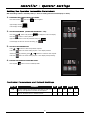
With the Holding Cabinet in ‘Stand-By’ Mode (i.e. Power to Holding Cabinet but both displays are blank).
1. ENTERING THE OPERATOR SETTING MODE.
Press and hold 'Set' and ‘Temp’ buttons together.
Upper Display will show .
Lower Display will flash .
2. SETTING PASSWORD (OPERATOR PASSWORD - 123).
Press and hold button until password is displayed on the lower display.
Press ‘Set’ button to confirm password.
Upper Display will show one of the parameter codes, eg.
Lower Display will show the value of the setting, eg.
3. SETTING THE PARAMETERS.
Press or buttons to select the parameter required.
Press ‘Set’ button to confirm setting required. Lower Display will flash.
While Lower Display is flashing, press or buttons to select the value required.
Press ‘Set’ button to confirm setting required. Lower Display will stop flashing.
4. EXITING THE OPERATOR SETTING MODE.
Press ‘On/Off’ button to return to Stand-By Mode.
U o M Pass 0
L-O
Time Light stays On.
Duration of tim e for w hich light
stays ‘On’. Pressing ‘Light’ Key will turn oven light ‘On / Off’. If 1-
60min set, oven light will turn off after set time elapsed.
0 60 min 0 U
voL Buzzer Volume.
Volume of buzzer can be adjusted be-
tween ‘O’ -No Buzzer and ‘10’ maximum volume.
0 10 --- 5 U

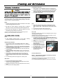
Cleaning and Maintenance
11
To achieve the best results, cleaning must be regular and thorough.
If any small faults occur, have them looked at promptly. Don't wait
until they cause a complete breakdown.
NOTE:
Carefully read and follow the safety instructions on the label
of the cleaning product to be used.
DO NOT use harsh abrasive scouring pads or abrasive
detergents as they could damage the Hot Holding Cabinet.
Ensure that any detergent or cleaning material has been
completely removed after each cleaning.
To keep your Hot Holding Cabinet clean and operating at peak
efficiency, follow the procedures shown below:-
NOTE:
If Hot Holding Cabinet usage is very high, cleaning
procedure should be carried out more frequently.
Stainless Steel Surfaces
1. Clean exterior surfaces of Hot Holding Cabinet with, a damp
cloth moistened with a mild detergent solution, or a soft bristled
brush.
2. Hardened deposits or discolouration may require a good quality
stainless steel cleaner. Always apply cleaner when appliance is
cold and rub in direction of the grain.
3. Dry all components thoroughly with a dry cloth and polish with
a soft dry cloth.
4. Ensure Hot Holding Cabinet chamber is cool. Do not use wire
brushes, steel wool or other abrasive materials to clean interior
of cabinet.
5. Once a week, remove side racks and clean any build up of
product from Hot Holding Cabinet interior, using a mild anti
bacterial detergent and hot water solution and a soft bristled
brush.
6. Dry Hot Holding Cabinet thoroughly with a soft dry cloth.
Side Racks
1. Lift up and remove side racks for cleaning.
2. Clean racks with a mild anti bacterial detergent and hot water
solution, using a soft bristled brush.
3. Dry racks thoroughly with a dry cloth and polish with a soft dry
cloth.
4. Refit racks into Hot Holding Cabinet.
Condensation Channel
1. Below the door is a condensation channel for collecting door
condensation run-off. This is then fed into a condensation pan.
2. Empty condensation pan on a regular basis and once a week,
wipe out condensation channel and pan with a damp cloth
moistened with warm water and a mild detergent solution.
3. Dry with a soft dry cloth.
Door
1. Wash door with warm water and a mild detergent solution
using a soft sponge in straight lines up and down inner and
outer surfaces of door. Rinse with clean, warm water and dry
off.
2. Dry the door thoroughly with a soft dry cloth.
3. Clean door glass with a conventional glass cleaner.
Door Seal
Clean door seal with warm water and a detergent solution using a
soft sponge when required.
Should the door seal become dirty, it can be removed for a more
thorough cleaning should this be necessary:-
1. To remove 1 piece seal, pull seal forward until it pulls out of
location groove around the door.
Note the way seal is fitted
to door, with lip facing inwards.
2. Check seal for wear and damage and replace if damaged or
worn.
3. The seal may be washed in a
sink, taking care not to cut or
damage the seal .
4. Dry the seal thoroughly with a
soft dry cloth before re-fitting.
5. To refit seal, have seal lip facing
into centre of door.
6. Press seal into locating groove
around door until seal is
properly located.
Periodic Maintenance
NOTE: All maintenance operations should only be carried
out by a qualified service person.
Controls and mechanical parts should be checked and adjusted
periodically by a qualified service person.
It is recommended that the appliance is serviced every 6 months.
Pull Seal out of locating channel
Condensation Collection Pan

Fault Finding
12
This section provides a reference to the more common problems
that may occur during the operation of your Hot Holding Cabinet.
This fault finding guide is intended to help you correct, or at least
accurately diagnose problems with your Hot Holding Cabinet.
When fault finding a problem, always use a process of elimination
starting with the simplest solution and working through to the most
complex. Never overlook the obvious.
You may encounter a problem not covered in this section, please
contact your service provider who will require the following
information:-
Model and Serial Number of Hot Holding Cabinet, can be
found on the Technical Data Plate located on front right
hand side panel of the cabinet.
The Hot Holding Cabinet does not
operate / start.
Mains isolating switch on the wall, circuit
breaker or fuses are 'Off' at the power board.
Transformer faulty.
Control Panel is faulty.
Turn 'On’.
Call for service.
Call for service.
No Heat.
No operating temperature set on the Control
Panel.
Cabinet Overtemp tripped.
Heating Relay faulty.
Control Panel faulty.
The element is faulty.
Set an operating temperature on the Control
Panel.
Call for Service.
Call for Service.
Call for Service.
Call for Service.
Slow Recovery.
Overloading of cabinet.
Door opened unnecessarily.
Reduce batch size.
Do not open unnecessarily.
The Hot Holding Cabinet lights not
illuminating.
Blown bulbs.
Control Panel faulty.
Replace bulbs.
Call for service.
Fan does not operate.
Fan obstructed.
Fan motor faulty.
Control Panel faulty.
Clear obstruction.
Call for service.
Call for service.
Door does not close.
Tray in way of door.
Door seal obstruction.
Correctly position tray in rack.
Correctly refit door seal. (Refer to the ‘Cleaning’
Section).

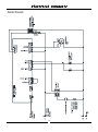
Electrical Schematic
13

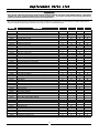
Replacement Parts List
14
When ordering replacement parts, please quote part number and description as listed below. If part required is not listed, request part by
description and quote model number and serial number which is shown on Technical Data Plate.
Only genuine authorized replacement parts should be used for servicing and repair of this Holding Cabinet. Instructions
supplied with parts should be followed when replacing components. For further information and servicing instructions,
contact your nearest authorized service provider or Turbofan Dealer.
H8D-UC H8D-FS-UC H10D H10D-FS
240219 Control Panel Laminated H10D
240243 Control Panel Laminated H8D-UC
240270 Digital Controller Kit
234429 Transformer 208 / 240 - 12V, 20VA
234430 Transformer 120V - 24VAC, 15VA (110-120V Only)
026160 Terminal Block FV110B
238881 Relay DPST HF92F 30A 240VAC
240311 Relay DPST HF92F 30A 120VAC
237447K Temperature Probe Kit
234080 Element 240V, 1200W (H8D-UC, H10D, 220-240V)
234081 Element 120V, 1200W (H8D-UC, H10D, 110-120V)
240177 Element 240V, 1900W (H8D-FS-UC, H10D-FS)
242024K Motor 208 / 240V, 50/60Hz
025387K Motor 110 / 120V, 60Hz
022042 Fan Blade
240402 Overtemp Switch
236214 Lamp Holder G9 25W (Bulb included.)
231814 Lamp Bulb G9/25W 230V HALOGEN
233884 Lamp Bulb G9/25W 120V HALOGEN
242092 Gasket
021352 Glass Lens
021353 Support Frame
234626 Door Hinge Set Top (H8D-FS-UC, H10D-FS)
234627 Door Hinge Set Bottom (H8D-FS-UC, H10D-FS)
234680 Door Pivot Pin Assembly
237167 Door Hinge Set (Includes Top & Bottom Hinge) (H8D-UC, H10D)
240116 Magnet Catch Plate
237741 Door Magnet
238378 Door Handle (H8D-UC, H8D-FS-UC)
236473 Door Handle (H10D, H10D-FS)
241442 Door Seal H8D-UC
241443 Door Seal H8D-FS-UC
241440 Door Seal H10D
241444 Door Seal H10D-FS
238390 Castor 65mm Rigid PU
238391 Castor 65mm Swivel PU D/Brake
234216 Castor 75mm Rigid Rubber
234217 Castor 75mm Swivel Rubber D/Brake
238423 Rack LH H8D-UC (1/1 GN)
238424 Rack RH H8D-UC (1/1 GN)
238730 Rack H8D-UC (1/2 US Pan)
240241 Rack H8D-FS-UC
236521 Rack RH H10D (1/1 GN)
236622 Rack LH H10D (1/1 GN)
238731 Rack H8D-UC (1/2 US Pan)
240217 Rack H10D-FS
239482 Condensation Collection Pan

-
 1
1
-
 2
2
-
 3
3
-
 4
4
-
 5
5
-
 6
6
-
 7
7
-
 8
8
-
 9
9
-
 10
10
-
 11
11
-
 12
12
-
 13
13
-
 14
14
-
 15
15
-
 16
16
-
 17
17


Moffat H10D Operating instructions
- Category
- Cookers
- Type
- Operating instructions
Ask a question and I''ll find the answer in the document
Finding information in a document is now easier with AI