JUNG A5091TSEM Operating instructions
- Category
- Car kits
- Type
- Operating instructions
This manual is also suitable for


Table of contents
1 Safety instructions ............................................................................................................ 3
2 Device components .......................................................................................................... 3
3 Intended use..................................................................................................................... 4
4 Information for electrically skilled persons........................................................................ 4
4.1 Mounting and electrical connection........................................................................ 5
4.2 Commissioning ...................................................................................................... 6
5 Technical data .................................................................................................................. 6
6 Accessories ...................................................................................................................... 7
7 Warranty ........................................................................................................................... 7
2 / 7
32587823 14.06.2023
j0082587823
Push-button extension module, Room controller extension module

1 Safety instructions
Electrical devices may be mounted and connected only by electrically skilled
persons.
Serious injuries, fire or property damage are possible. Please read and follow the
manual fully.
Use only the enclosed plastic screws for fastening to the supporting frame! Otherwise
safe operation cannot be ensured. Electrostatic discharges can cause defects in the
device.
This manual is an integral part of the product, and must remain with the customer.
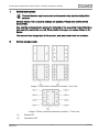
2 Device components
Image1: Push-button extension modules - front view
Image2: Room controller extension modules - Front view
(1) Status LED
(2) Operation LED
Push-button extension module, Room controller extension module
3 / 7
32587823 14.06.2023
j0082587823

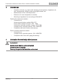
3 Intended use
– Operation of loads, e.g. light on/off, dimming, blinds up/down, brightness val-
ues, temperatures, calling up and saving light scenes, etc.
– Measurement of the room temperature
– Extension for room temperature controller
– Mounting in appliance box according to DIN 49073
Push-button extension modules:
– Connection to
Universal push-button module 529x1 ST,
Push button module Universal ..509..: TSM,
Continuous controller module, 2-gang ..5178 TSM,
Compact room controller module ..519.. KRMTSD
– Completion with set of buttons (Accessory)
Room controller extension module
– Connection to
Compact room controller module ..519.. KRMTSD
– Completion with Cover kit 2-gang (Accessory)
4 Information for electrically skilled persons
DANGER!
Electric shock when live parts are touched.
Electric shocks can be fatal.
Cover up live parts in the installation environment.
Push-button extension module, Room controller extension module
4 / 7
32587823 14.06.2023
j0082587823

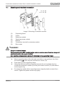
4.1 Mounting and electrical connection
Image3: Mounting of extension module
(3) Supporting frame
(4) Frame
(5) Extension module
(6) Fastening screws, plastic
(7) Buttons
(8) Connection terminal for extension module
(9) Box screws
DANGER!
Danger of electrical shock!
When mounting with 230 V socket outlets under a common cover there is a danger of
electrical shocks in the event of a fault!
Use only the enclosed plastic screws for fastening to the supporting frame!
■ Mount supporting frame (3) in the right orientation on an appliance box. Note
the marking TOP. Use only the enclosed box screws (10).
■ Push frame (4) onto supporting frame.
■ Using the white and yellow connection terminal (8) and a suitable bus line,
connect the extension module (5) to the push-button module (10) and attach it
to the support ring.
■ Fix extension module (5) to supporting frame using the plastic screws (6) en-
closed. Tighten the plastic screws only lightly.
Push-button extension module, Room controller extension module
5 / 7
32587823 14.06.2023
j0082587823

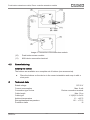
Image4: Connection of the extension module
(10) Push-button sensor module
(11) KNX device connection terminal
4.2 Commissioning
Installing the buttons
The buttons are available as a complete set of buttons (see accessories).
■ Place the buttons on the device in the correct orientation and snap in with a
short push.
5 Technical data
Rated voltage DC 20 V
Current consumption Max. 6 mA
Connection type for bus Device connection terminal
Cable length Max. 30 m
Cable type J-Y(St)Y 2×2×0.8
Ambient temperature -5 ... +45°C
Storage/transport temperature -25 ... +70°C
Protectionclass III
Push-button extension module, Room controller extension module
6 / 7
32587823 14.06.2023
j0082587823

6 Accessories
Cover kit 1-gang Art. no. ..501 TSA..
Cover kit 2-gang Art. no. ..502 TSA..
Cover kit 3-gang Art. no. ..503 TSA..
Cover kit 4-gang Art. no. ..504 TSA..
7 Warranty
The warranty is provided in accordance with statutory requirements via the specialist
trade.
ALBRECHT JUNG GMBH & CO. KG
Volmestraße 1
58579 Schalksmühle
GERMANY
Telefon: +49 2355 806-0
Telefax: +49 2355 806-204
www.jung.de
Push-button extension module, Room controller extension module
7 / 7
32587823 14.06.2023
j0082587823
-
 1
1
-
 2
2
-
 3
3
-
 4
4
-
 5
5
-
 6
6
-
 7
7


JUNG A5091TSEM Operating instructions
- Category
- Car kits
- Type
- Operating instructions
- This manual is also suitable for
Ask a question and I''ll find the answer in the document
Finding information in a document is now easier with AI
Related papers
-
JUNG A5092TSEM Operating instructions
-
-
-
-
-
-
-
-
-