Vertiv Liebert® Mini-Mate 3, 4 and 5 Ton (10.5, 14 and 17.5 kW) Capacity, Ceiling User manual
- Category
- Split-system air conditioners
- Type
- User manual

Liebert® Mini-Mate Variable
Capacity Indoor,Water/Glycol-cooled
or Air-cooled CondensingUnit
Installer/User Guide
3, 4 and5 Ton(10.5, 14 and 17.5 kW) Capacity, Ceiling-mounted,60Hz

Vertiv™ | Liebert® Mini-Mate Water/Glycol-cooled or Air-cooled Condensing Unit Installer/User Guide
Technical Support Site
If you encounter any installation or operational issues with your product, check the pertinent section of this
manual to see if the issue can be resolved by following outlined procedures.
Visit https://www.vertiv.com/en-us/support/ for additional assistance.
The information contained in this document is subject to change without notice and may not be suitable
for all applications. While every precaution has been taken to ensure the accuracy and completeness of
this document, Vertiv assumes no responsibility and disclaims all liability for damages resulting from use
of this information or for any errors or omissions.
Vertiv recommends installing a monitored fluid detection system that is wired to activate the automatic
closure of field-installed coolant fluid supply and return shut off valves, where applicable, to reduce the
amount of coolant fluid leakage and consequential equipment and building damage. Refer to local
regulations and building codes relating to the application, installation, and operation of this product. The
consulting engineer, installer and/or end user is responsible for compliance with all applicable laws and
regulations relating to the application, installation, and operation of this product.
The products covered by this instruction manual are manufactured and/or sold by Vertiv. This
document is the property of Vertiv and contains confidential and proprietary information owned by
Vertiv. Any copying, use or disclosure of it without the written permission of Vertiv is strictly prohibited.
Names of companies and products are trademarks or registered trademarks of the respective
companies. Any questions regarding usage of trademark names should be directed to the original
manufacturer.
Vertiv™ Liebert® Mini-Mate Water/Glycol-cooled or Air-cooled Condensing Unit Installer/User Guide

TABLE OF CONTENTS
1 Important Safety Instructions 1
2 Nomenclature and Components 7
2.1 Remote, Indoor Water/Glycol-cooled or Air-cooled Condensing Unit Model Number Nomenclature 7
2.2 Component Location 8
3 Pre-installation PreparationandGuidelines 9
3.1 Planning Dimensions 9
3.1.1 Location Considerations for the Indoor Water/Glycol Condensing Unit 9
3.1.2 Location Considerations for the Indoor Air-cooled Condensing Unit 10
3.2 Connections and System Setup 10
3.3 Condensing Unit Weights 10
3.4 Equipment Inspection and Handling 10
4 Installation 13
4.1 Installing Ceiling-mounted Units 13
4.1.1 Installing Suspension Rods andMounting Ceiling Units 13
4.1.2 Guidelines for Ducted Systems 14
5 Piping and Refrigerant Requirements 17
5.1 Water/Glycol Loop Piping Guidelines 18
5.2 Refrigerant Piping 19
5.2.1 Refrigerant Piping Guidelines 20
5.2.2 Piping When Condensing Unit is Above or Below Evaporator 22
5.3 Refrigerant Line Sizes and Equivalent Lengths 23
5.3.1 Refrigerant Charge Requirements forWater/Glycol-cooled or Air-cooled Systems 23
5.4 Additional Oil Requirements for Scroll Compressors 24
5.5 Evacuation, Leak Testing, and Charging for Water/Glycol Systems 26
5.5.1 Evacuation and Leak Testing Water/Glycol-cooled Systems 26
5.5.2 Break Vacuum 28
5.5.3 Charging Water/Glycol-cooled Systems 28
5.5.4 Optimizing Refrigerant Charge on Water/Glycol Units 29
5.5.5 Documenting Refrigerant Charge on Water/Glycol-cooled Units 30
5.6 Evacuation, Leak Testing, and Charging for Air Cooled Systems 30
5.6.1 Evacuation and Leak Testing Air-cooled Systems 30
5.6.2 Break Vacuum 32
5.6.3 Charging Air-cooled Systems 32
5.6.4 Additional Compressor Oil 33
5.6.5 Documenting Refrigerant Charge and Oil Addition 34
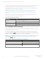
6 Electrical Connection Requirements 35
6.1 Low Voltage, Control Connections 36
Proprietary and Confidential ©2023 Vertiv Group Corp. i
Vertiv™ Liebert® Mini-Mate Water/Glycol-cooled or Air-cooled Condensing Unit Installer/User Guide

6.1.1 Water/Glycol-cooled Condensing Unit Control Connections 37
6.1.2 Air-cooled Condensing Unit Control Connections 37
7 Maintenance 39
7.1 Coaxial Condenser Maintenance 40
7.2 Regulating Valve Maintenance 40
7.3 Glycol Solution Maintenance 40
7.4 Facility Fluid and Piping Maintenance forWaterandGlycolSystems 41
7.5 Compressor Maintenance 41
7.5.1 Compressor Oil 41
7.5.2 Replacement Compressors 42
7.5.3 Compressor Motor Burnout 42
7.5.4 Unloading Solenoid(s) on a Digital Scroll Compressor 42
7.5.5 Replacing the Compressor 42
7.6 Blower Package Maintenance 43
7.6.1 Fan Impeller and Motor Bearing Maintenance 43
7.6.2 Air Distribution Inspection 43
Appendices 45
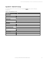
Appendix A: Technical Support and Contacts 45
Appendix B: Submittal Drawings 47
ii Proprietary and Confidential ©2023 Vertiv Group Corp.
Vertiv™ Liebert® Mini-Mate Water/Glycol-cooled or Air-cooled Condensing Unit Installer/User Guide

1 Important Safety Instructions
SAVE THESE INSTRUCTIONS
This manual contains important safety instructions that should be followed during the installation and maintenance of the
Vertiv™ Liebert®Water/Glycol-cooled or Air-cooled Condensing Unit. Read this manual thoroughly before attempting to
install or operate this unit.
Only qualified personnel should move, install or service this equipment.
Adhere to all warnings, cautions, notices and installation, operating and safety instructions on the unit and in this manual.
Follow all installation, operation and maintenance instructions and all applicable national and local building, electrical and
plumbing codes.
WARNING! Arc flash and electric shock hazard. Open all local and remote electric power-supply disconnect
switches, verify with a voltmeter that power is Off and wear appropriate, OSHA-approved personal protective
equipment (PPE) per NFPA 70E before working within the electric control enclosure. Failure to comply can
cause serious injury or death. Customer must provide earth ground to unit, per NEC, CEC and local codes, as
applicable. Before proceeding with installation, read all instructions, verify that all the parts are included and
check the nameplate to be sure the voltage matches available utility power. The Vertiv™ Liebert® iCOM™
controller does not isolate power from the unit, even in the “Unit Off” mode. Some internal components
require and receive power even during the “Unit Off” mode of the Liebert® iCOM™ controller. The only way to
ensure that there is NO voltage inside the unit is to install and open a remote disconnect switch. Refer to unit
electrical schematic. Follow all local codes.
WARNING! Risk of electric shock. Can cause equipment damage, injury or death. Open all local and remote
electric power supply disconnect switches and verify with a voltmeter that power is off before working within
any electric connection enclosures. Service and maintenance work must be performed only by properly
trained and qualified personnel and in accordance with applicable regulations and manufacturers’
specifications. Opening or removing the covers to any equipment may expose personnel to lethal voltages
within the unit even when it is apparently not operating and the input wiring is disconnected from the
electrical source.
WARNING! Risk of electric shock. Can cause serious injury or death. The Liebert® iCOM™ microprocessor
does not isolate power from the unit, even in the "Unit Off" mode. Some internal components require and
receive power even during the "unit off" mode of the Liebert® iCOM™ control. Open all local and remote
electric power disconnect switches and verify with a voltmeter that power is Off before working on any
component of the system.
1 Important Safety Instructions Proprietary and Confidential ©2023 Vertiv Group Corp. 1
Vertiv™ Liebert® Mini-Mate Water/Glycol-cooled or Air-cooled Condensing Unit Installer/User Guide

WARNING! Risk of over-pressurization of the refrigeration system. Can cause explosive discharge of high-
pressure refrigerant, loss of refrigerant, environmental pollution, equipment damage, injury, or death. This
unit contains fluids and gases under high pressure. Use extreme caution when charging the refrigerant
system. Do not pressurize the system higher than the design pressure marked on the unit's nameplate.
Relieve pressure before cutting into or making connections/disconnections to the piping system. Local
building or plumbing codes may require installing a pressure-relief device in the system. Consult local
building and plumbing codes for installation requirements of additional pressure-relief devices when isolation
valves are field installed. Do not isolate any refrigerant circuit from over-pressurization protection.
WARNING! Risk of contact with high speed, rotating fan blades. Can cause injury or death. Open all local and
remote electric power supply disconnect switches, verify with a voltmeter that power is off, and verify that all
fan blades have stopped rotating before working in the unit cabinet.
WARNING! Risk of ceiling collapse and heavy unit falling. Can cause building and equipment damage, serious
injury or death. Verify that the supporting roof structure is capable of supporting the weight of the unit(s)
and the accessories, see Table 3.2 on page10 , for unit weights. Be sure to securely anchor the top ends of
the suspension rods. Make sure all nuts are tight.
WARNING! Risk of improper moving. Can cause equipment damage, injury or death. Use only lifting
equipment that is rated for the unit weight by an OSHA-certified rating organization. The center of gravity
varies depending on the unit size and selected options. The slings must be equally spaced on either side of
the center of gravity indicator.
See Table 3.2 on page10 , for unit weights.
WARNING! Risk of improper piping installation, leak checking, fluid chemistry and fluid maintenance can
cause equipment damage and personal injury. Installation and service of this equipment should be done only
by qualified personnel who have been specially-trained in the installation of air-conditioning equipment and
who are wearing appropriate, OSHA-approved PPE.
WARNING! Risk of improper wiring, piping, moving, lifting and handling. Can cause equipment damage,
serious injury or death. Installation and service of this equipment should be done only by qualified personnel
who have been specially-trained in the installation of air-conditioning equipment and who are wearing
appropriate, OSHA-approved PPE.
WARNING! Risk of improper wire sizing/rating and loose electrical connections. Can cause overheated wire
and electrical connection terminals resulting in smoke, fire, equipment and building damage, injury or death.
Use correctly sized copper wire only and verify that all electrical connections are tight before turning power
On. Check all electrical connections periodically and tighten as necessary.
2 Proprietary and Confidential ©2023 Vertiv Group Corp. 1 Important Safety Instructions
Vertiv™ Liebert® Mini-Mate Water/Glycol-cooled or Air-cooled Condensing Unit Installer/User Guide

CAUTION: Risk of excessive refrigerant line pressure. Can cause tubing and component rupture resulting in
equipment damage and personal injury. Do not close off refrigerant-line isolation valve for repairs unless a
pressure-relief valve is field- installed in the line between the isolation valve and the check valve. The
pressure-relief valve must be rated 5% to 10% higher than the system-design pressure. An increase in
ambient temperature can cause the pressure of the isolated refrigerant to rise and exceed the system-design
pressure rating (marked on the unit nameplate).
CAUTION: Risk of contact with sharp edges, splinters, and exposed fasteners. Can cause injury. Only properly
trained and qualified personnel wearing appropriate, OSHA-approved PPE should attempt to move, lift,
remove packaging from or prepare the unit for installation.
CAUTION: Risk of contact with hot surfaces. Can cause injury. The compressor, refrigerant-discharge lines,
and some electrical components are extremely hot during unit operation. Allow sufficient time for them to
cool to a touch-safe temperature before working within the unit cabinet. Use extreme caution and wear
appropriate, OSHA-approved PPE when working on or near hot components.
CAUTION: Risk of contacting caustic substances. Can cause injury. Avoid touching or contacting the gas and
oils with exposed skin. Severe burns will result. Wear appropriate, OSHA-approved PPE when handling
contaminated parts.
NOTICE
Risk of improper power-supply connection. Can cause equipment damage and loss of warranty coverage.
Prior to connecting any equipment to a main or alternate power source (for example: back-up generator
systems) for start-up, commissioning, testing, or normal operation, ensure that these sources are correctly
adjusted to the nameplate voltage and frequency of all equipment to be connected. In general, power-source
voltages should be stabilized and regulated to within ±10% of the load nameplate nominal voltage. Also, ensure
that no three-phase sources are single-phased at any time.
NOTICE
Risk of oil contamination with water. Can cause equipment damage.
Because water is the enemy of a reliable refrigeration system, extreme care must be used when opening systems
during service. If water is absorbed into the POE oil, it will not be easily removed and will not be removed through
the normal evacuation process. If the oil is too wet, it may require an oil change. POE oils also have a property that
makes them act as a solvent in a refrigeration system. Maintaining system cleanliness is extremely important
because the oil will tend to bring any foreign matter back to the compressor.
1 Important Safety Instructions Proprietary and Confidential ©2023 Vertiv Group Corp. 3
Vertiv™ Liebert® Mini-Mate Water/Glycol-cooled or Air-cooled Condensing Unit Installer/User Guide

NOTICE
Risk of leaking water/glycol. Can cause equipment and building damage.
Improper installation, application, and service practices can result in water leakage from the unit. Do not mount
this unit over equipment and furniture that can be damaged by leaking water. Install a water-tight drain pan with
a drain connection under the cooling unit and the ceiling-mounted water/glycol condensing unit. Route the drain
pan to a frequently-used maintenance sink so that running water can be observed and reported in a timely
manner. Post a sign to alert people to report water flowing from the secondary drain pan. We recommend
installing monitored leak detection equipment for the unit and supply lines and in the secondary drain pan.
Check drain lines periodically for leaks, sediment buildup, obstructions, kinks and/or damage and verify that they
are free running.
NOTICE
Risk of piping-system corrosion and freezing fluids. Can cause leaks resulting in equipment and expensive
building damage. Cooling coils and piping systems are at high risk of freezing and premature corrosion. Fluids in
these systems must contain an inhibitor to prevent premature corrosion.
The system coolant fluid must be analyzed by a competent fluid-treatment specialist before start up to establish
the inhibitor level and evaluated at regularly scheduled intervals throughout the life of the system to determine
the pattern of inhibitor depletion. The fluid complexity and variations of required treatment programs make it
extremely important to obtain the advice of a competent and experienced fluid-treatment specialist and follow a
regularly scheduled coolant-fluid system-maintenance program.
Fluid chemistry varies greatly as do the required additives, called inhibitors, that reduce the corrosive effect of
the fluids on the piping systems and components.
The chemistry of the coolant fluid used must be considered, because some sources may contain corrosive
elements that reduce the effectiveness of the inhibited formulation. Sediment deposits prevent the formation of
a protective oxide layer on the inside of the coolant system components and piping. The coolant fluid must be
treated and circulating through the system continuously to prevent the buildup of deposits and/or growth of
bacteria. Proper inhibitor maintenance must be performed to prevent corrosion of the system.
Consult fluid manufacturer for testing and maintenance of inhibitors.
Commercial-grade coolant fluid is generally less corrosive to the common metals of construction than water
itself. It will, however, assume the corrosivity of the coolant fluid from which it is prepared and may become
increasingly corrosive with use if not properly inhibited.
Vertiv recommends installing a monitored fluid-detection system that is wired to activate the automatic-closure
of field-installed coolant-fluid supply and return shut-off valves to reduce the amount of coolant-fluid leakage
and consequential equipment and building damage. The shut-off valves must be sized to close-off against the
maximum coolant-fluid system pressure in case of a catastrophic fluid leak.
NOTICE
Risk of frozen pipes and corrosion from improper coolant mixture. Can cause water leaks resulting in equipment
and building damage.
When the cooling unit or piping may be exposed to freezing temperatures, charge the system with the proper
percentage of glycol and water for the coldest design ambient temperature. Automotive antifreeze is
unacceptable and must NOT be used in any glycol fluid system. Use only HVAC glycol solution that meets the
requirements of recommended industry practices. Do not use galvanized pipe.
4 Proprietary and Confidential ©2023 Vertiv Group Corp. 1 Important Safety Instructions
Vertiv™ Liebert® Mini-Mate Water/Glycol-cooled or Air-cooled Condensing Unit Installer/User Guide

NOTICE
Risk of no-flow condition. Can cause equipment damage. Do not leave the water/coolant fluid-supply circuit in a
no-flow condition. Idle fluid allows the collection of sediment that prevents the formation of a protective oxide
layer on the inside of tubes. Keep unit switched On and water/coolant fluid-supply circuit system operating
continuously.
NOTICE
Risk of doorway/hallway interference. Can cause unit and/or structure damage. The unit may be too large to fit
through a doorway or hallway while on the skid. Measure the unit and passageway dimensions, and refer to the
installation plans prior to moving the unit to verify clearances.
NOTICE
Risk of damage from forklift. Can cause unit damage. Keep tines of the forklift level and at a height suitable to fit
below the skid and/or unit to prevent exterior and/or underside damage.
NOTICE
Risk of improper storage. Can cause unit damage.
Keep the unit upright, indoors and protected from dampness, freezing temperatures and contact damage.
Agency Listed
Standard 60-Hz units are CSA Certified to the harmonized U.S. and Canadian product safety standard CSA C22.2 No 236/UL
1995 for “Heating and Cooling Equipment” and are marked with the CSA c-us logo.
1 Important Safety Instructions Proprietary and Confidential ©2023 Vertiv Group Corp. 5
Vertiv™ Liebert® Mini-Mate Water/Glycol-cooled or Air-cooled Condensing Unit Installer/User Guide

6 Proprietary and Confidential ©2023 Vertiv Group Corp. 1 Important Safety Instructions
This page intentionally left blank
Vertiv™ Liebert® Mini-Mate Water/Glycol-cooled or Air-cooled Condensing Unit Installer/User Guide

2 Nomenclature and Components
This section describes the model number for Vertiv™ Liebert® Indoor Water/Glycol-cooled or Air-cooled Condensing Units
and components.
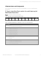
2.1 Remote, Indoor Water/Glycol-cooled or Air-cooled Condensing Unit
Model Number Nomenclature
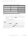
Table 2.2 below describes each digit of the model number.
1 2 3 4 5 6 7 8 9 10
M T C 3 8 W D A 2 1
Table 2.1 Water/Glycol Condensing Unit Model Number Example
Digit and Description
Digits 1, 2, 3 = The base unit
MTC = Liebert® Mini-Mate Variable Capacity condensing unit
Digit 4, 5 = Nominal Capacity
38 = 38 kBtuh, 3-ton, 60Hz (W/G cooled)
36 = 36 kBtuh, 3-ton, 60Hz (Air cooled)
48 = 48 kBtuh, 4-ton, 60 Hz (Air cooled)
55 = 55 kBtuh, 4-ton, 60 Hz (W/G cooled)
65 = 65 kBtuh, 5-ton, 60Hz (Air cooled)
69 = 69 kBtuh, 5-ton, 60 Hz (W/G cooled)
Digit 6 = Cooling type
W = Water/Glycol-cooled
A = Air-cooled
Digit 7 = Head-pressure control
D = 2-way high-pressure fluid-regulating valve (W/G cooled)
T = 3-way high-pressure fluid-regulating valve (W/G cooled)
L = Liebert® Lee-Temp Receiver (Air cooled)
Table 2.2 Model Number Digit Definitions for Water/Glycol-cooled or Air-cooled Condensing Units
2 Nomenclature and Components Proprietary and Confidential ©2023 Vertiv Group Corp. 7
Vertiv™ Liebert® Mini-Mate Water/Glycol-cooled or Air-cooled Condensing Unit Installer/User Guide

Digit and Description
Digit 8 = Supply power
A = 460V / 3ph / 60Hz
B = 575V / 3ph / 60Hz (4- and 5-ton only)
P = 208/230V / 1ph / 60Hz (3-ton only)
X = 277V / 1ph / 60 Hz (3-ton only)
Y = 208/230V / 3ph / 60Hz
Digit 9 = Compressor type
2 = 2-stage scroll
Digit 10 = Refrigerant
1 = R-410A field-supplied and charged
Table 2.2 Model Number Digit Definitions for Water/Glycol-cooled or Air-cooled Condensing Units (continued)
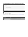
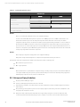
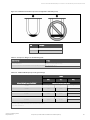
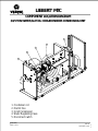
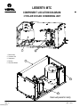
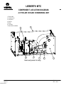
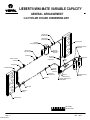
2.2 Component Location
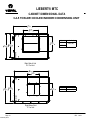
The unit component locations are described in the submittal documents included in the Submittal Drawings on page47 .
The following tables list the relevant documents by number and title.
Document Number Title
DPN004989 Component location diagram 3/4/5 Ton Water/Glycol-cooled condensing unit
10031570 Component location diagram 3/4/5 Ton Air-cooled condensing unit
Table 2.3 Component Location Drawings
8 Proprietary and Confidential ©2023 Vertiv Group Corp. 2 Nomenclature and Components
Vertiv™ Liebert® Mini-Mate Water/Glycol-cooled or Air-cooled Condensing Unit Installer/User Guide

3 Pre-installation PreparationandGuidelines
NOTE: Before installing unit, determine whether any building alterations are required to run piping and wiring. Follow
all unit dimensional drawings and refer to the submittal engineering dimensional drawings of individual units for
proper clearances.
Refer to Remote, Indoor Water/Glycol-cooled or Air-cooled Condensing Unit Model Number Nomenclature on page7 , and
submittal drawings to determine the type of system being installed and anticipate building alterations and piping needed.
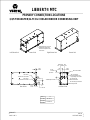
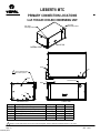
The unit dimensions, pipe-connection locations, and piping schematics are described in the submittal documents included in
the Submittal Drawings on page47 .
•Allow at least the minimum recommended clearances for maintenance and service. See the appropriate
submittal drawings for dimensions.
•Be mindful of the placement of the Condensing Unit in relation to the connected evaporator unit, other units,
equivalent piping distances, and differences in elevation between the Condensing Unit and connected
evaporator unit.
•When applications do not meet or will exceed any of these specifications, contact your Vertiv representative.
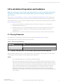
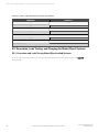
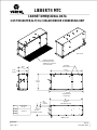
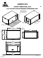
3.1 Planning Dimensions
The unit dimensions described in the submittal documents included in the Submittal Drawings on page47 .
The following table lists the relevant documents by number and title.
Document Number Title
DPN004889 Cabinet dimensions, 3, 4, and 5 ton, Water/Glycol-cooled
10030172 Cabinet dimensions, 3, 4, and 5 ton Air-cooled condensing unit
Table 3.1 Dimension Planning Drawings
3.1.1 Location Considerations for the Indoor Water/Glycol Condensing Unit
When determining installation locations, consider that these units contain water/glycol and that leaks from ceiling-mounted
condensing units can cause damage to sensitive equipment and furniture below.
NOTICE
Risk of leaking water/glycol. Can cause equipment and building damage.
Improper installation, application, and service practices can result in water leakage from the unit. Do not mount
this unit over equipment and furniture that can be damaged by leaking water. Install a water-tight drain pan with
a drain connection under the cooling unit and the ceiling-mounted water/glycol condensing unit. Route the drain
pan to a frequently-used maintenance sink so that running water can be observed and reported in a timely
manner. Post a sign to alert people to report water flowing from the secondary drain pan. We recommend
installing monitored leak detection equipment for the unit and supply lines and in the secondary drain pan.
Check drain lines periodically for leaks, sediment buildup, obstructions, kinks and/or damage and verify that they
are free running.
3 Pre-installation
PreparationandGuidelines Proprietary and Confidential ©2023 Vertiv Group Corp. 9
Vertiv™ Liebert® Mini-Mate Water/Glycol-cooled or Air-cooled Condensing Unit Installer/User Guide

3.1.2 Location Considerations for the Indoor Air-cooled Condensing Unit
•In applications where the ceiling plenum is used as the heat rejection domain, the discharge air must be directed
away from the condensing unit air inlet and a screen must be added to the end of the discharge duct to protect
service personnel. Locate the air discharge a minimum of 4 ft. from an adjacent wall. Failure to do so may result in
reduced air flow and poor system performance.
•If the condensing unit draws air from the outside of the building, rain hoods must be installed. Hood intake and
duct work cross-sectional area dimensions should be equal to or greater than the area of the condensing unit
intake flange. In addition, install a triple-layer bird screen over rain hood openings to eliminate the possibility of
insects, birds, water or debris entering the unit. Avoid directing the hot exhaust air toward adjacent doors or
windows.
3.2 Connections and System Setup
•Electrical service is required for all models. Electrical service must conform to national and local electrical codes.
See equipment nameplate for details.
•Plan the routing of wiring and piping to the unit. Refer to the appropriate piping connection location drawings,
piping schematics, and electrical connection drawings for your system in the Submittal Drawings on page47 .
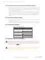
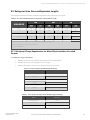
3.3 Condensing Unit Weights
Model # Weight, lb (kg)
MTC38W 237 (107.5)
MTC55W 237 (107.5)
MTC69W 237 (107.5)
MTC36A 350 (159)
MTC48A 408 (185)
MTC65A 408 (185)
Table 3.2 Condensing Unit Weights
3.4 Equipment Inspection and Handling
WARNING! Risk of improper moving, lifting, or handling of the unit. Can cause equipment damage, injury or
death. Read all of the following instructions and verify that all lifting and moving equipment is rated for the
weight of the unit before attempting to move, lift, remove packaging from or prepare the unit for installation.
Unit weights are specified in Table 3.2 above .
CAUTION: Risk of contact with sharp edges, splinters, and exposed fasteners. Can cause injury. Only properly
trained and qualified personnel wearing appropriate, OSHA-approved PPE should attempt to move, lift,
remove packaging from or prepare the unit for installation.
10 Proprietary and Confidential ©2023 Vertiv Group Corp. 3 Pre-installation
PreparationandGuidelines
Vertiv™ Liebert® Mini-Mate Water/Glycol-cooled or Air-cooled Condensing Unit Installer/User Guide

NOTICE
Risk of damage from forklift. Can cause unit damage. Keep tines of the forklift level and at a height suitable to fit
below the skid and/or unit to prevent exterior and/or underside damage.
When the unit arrives, inspect all items for any visible or concealed damage. Report any damage to the carrier immediately
and file a damage claim. Send a copy of the claim to your Vertiv representative.
If possible, maintain equipment and packaging until it is at the installation location.
3 Pre-installation
PreparationandGuidelines Proprietary and Confidential ©2023 Vertiv Group Corp. 11
Vertiv™ Liebert® Mini-Mate Water/Glycol-cooled or Air-cooled Condensing Unit Installer/User Guide

12 Proprietary and Confidential ©2023 Vertiv Group Corp. 3 Pre-installation
PreparationandGuidelines
This page intentionally left blank
Vertiv™ Liebert® Mini-Mate Water/Glycol-cooled or Air-cooled Condensing Unit Installer/User Guide

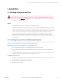
4 Installation
4.1 Installing Ceiling-mounted Units
WARNING! Risk of ceiling collapse and heavy unit falling. Can cause building and equipment damage, serious
injury or death. Verify that the supporting roof structure is capable of supporting the weight of the unit(s)
and the accessories, see Table 3.2 on page10 . Be sure to securely anchor the top ends of the suspension
rods. Make sure all nuts are tight.
NOTICE
Risk of leaking water/glycol. Can cause equipment and building damage.
Improper installation, application, and service practices can result in water leakage from the unit. Do not mount
this unit over equipment and furniture that can be damaged by leaking water. Install a water-tight drain pan with
a drain connection under the cooling unit and the ceiling-mounted water/glycol condensing unit. Route the drain
pan to a frequently-used maintenance sink so that running water can be observed and reported in a timely
manner. Post a sign to alert people to report water flowing from the secondary drain pan. We recommend
installing monitored leak detection equipment for the unit and supply lines and in the secondary drain pan.
Check drain lines periodically for leaks, sediment buildup, obstructions, kinks and/or damage and verify that they
are free running.
4.1.1 Installing Suspension Rods andMounting Ceiling Units
Refer to the Location Considerations for the Indoor Water/Glycol Condensing Unit on page9 and Location Considerations for
the Indoor Air-cooled Condensing Unit on page10 before beginning installation.
NOTE: Follow all national and local building, electrical and plumbing codes.
•The ceiling and ceiling supports of existing buildings may require reinforcements.
•Recommended clearance between ceiling grids and building structural members is the unit’s height plus 3in.
(76mm).
•Four 3/8-in.-16 TPI threaded suspension rods are required and field supplied. The factory-supplied 3/8-in.-16 TPI
hardware kit includes the remaining installation hardware for rod to unit.
To install the suspension rods:
1. Install the 4 field-supplied rods by suspending them from suitable building structural members so that they will
align with the 4 mounting locations on the unit base.
2. Securely anchor the top ends of the suspension rods.
3. Make sure all nuts are tight.
4 Installation Proprietary and Confidential ©2023 Vertiv Group Corp. 13
Vertiv™ Liebert® Mini-Mate Water/Glycol-cooled or Air-cooled Condensing Unit Installer/User Guide

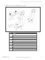
To lift and install the unit on the rods:
1. Referring to Figure 4.1 below , place the hex nuts (Item 2) on the threaded rods, and add the washer, sleeve, and
isolator (Items 3, 4, and 6) to the bracket holes on the unit.
2. Using a suitable lifting device that is rated for the weight of the unit (see Table 3.2 on page10 ), raise the unit
and pass the threaded rods through the 4 mounting locations in the unit base.
3. Attach the threaded rods to the flanges using the washer and plain nut (Items 7 and 8) from the hardware kit to
hold the unit in place as shown in Figure 4.1 below .
4. Adjust the plain nuts to distribute the weight of the unit evenly by the rods, making sure that the unit does not
rest on the ceiling grid and that the unit is level.
NOTE: The unit must be level to properly drain condensate.
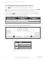
5. Use the Nylock nuts to "jam" the plain nuts in place as shown in Figure 4.1 below .
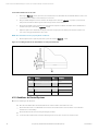
Figure 4.1 Installing threaded rods and hardware of ceiling-mounted units
Item Description Item Description
1 3/8-in. threaded rod, field-supplied 6 Isolator
2 3/8-in. hex nut 7 3/8-in. fender washer
3 3/8-in. washer 8 3/8-in. hex nut
4 Sleeve 9 3/8-in. Nylock locking nut
5 Bracket on unit 10 Unit base pan (reference)
4.1.2 Guidelines for Ducted Systems
Observe the following for all duct work:
•Duct work should be fabricated and installed in accordance with local and national codes.
•Use flexible duct work or nonflammable cloth collars to attach duct work to the unit and to control vibration
transmission to the building.
•Attach the duct work to the unit using the flanges provided.
•Locate the unit and duct work so that the discharge air does not short-circuit to the return air inlet.
14 Proprietary and Confidential ©2023 Vertiv Group Corp. 4 Installation
Vertiv™ Liebert® Mini-Mate Water/Glycol-cooled or Air-cooled Condensing Unit Installer/User Guide

•If the return air duct is short or if noise is likely to be a problem, sound-absorbing insulation should be used inside
the duct.
•Duct work should be suspended using flexible hangers. Duct work should not be fastened directly to the building
structure.
•For multiple unit installations, space the units so that the hot condensing unit exhaust air is not directed toward
the air inlet of an adjacent unit.
4 Installation Proprietary and Confidential ©2023 Vertiv Group Corp. 15
Vertiv™ Liebert® Mini-Mate Water/Glycol-cooled or Air-cooled Condensing Unit Installer/User Guide

16 Proprietary and Confidential ©2023 Vertiv Group Corp. 4 Installation
This page intentionally left blank
Vertiv™ Liebert® Mini-Mate Water/Glycol-cooled or Air-cooled Condensing Unit Installer/User Guide
Page is loading ...
Page is loading ...
Page is loading ...
Page is loading ...
Page is loading ...
Page is loading ...
Page is loading ...
Page is loading ...
Page is loading ...
Page is loading ...
Page is loading ...
Page is loading ...
Page is loading ...
Page is loading ...
Page is loading ...
Page is loading ...
Page is loading ...
Page is loading ...
Page is loading ...
Page is loading ...
Page is loading ...
Page is loading ...
Page is loading ...
Page is loading ...
Page is loading ...
Page is loading ...
Page is loading ...
Page is loading ...
Page is loading ...
Page is loading ...
Page is loading ...
Page is loading ...
Page is loading ...
Page is loading ...
Page is loading ...
Page is loading ...
Page is loading ...
Page is loading ...
Page is loading ...
Page is loading ...
Page is loading ...
Page is loading ...
Page is loading ...
Page is loading ...
Page is loading ...
Page is loading ...
-
 1
1
-
 2
2
-
 3
3
-
 4
4
-
 5
5
-
 6
6
-
 7
7
-
 8
8
-
 9
9
-
 10
10
-
 11
11
-
 12
12
-
 13
13
-
 14
14
-
 15
15
-
 16
16
-
 17
17
-
 18
18
-
 19
19
-
 20
20
-
 21
21
-
 22
22
-
 23
23
-
 24
24
-
 25
25
-
 26
26
-
 27
27
-
 28
28
-
 29
29
-
 30
30
-
 31
31
-
 32
32
-
 33
33
-
 34
34
-
 35
35
-
 36
36
-
 37
37
-
 38
38
-
 39
39
-
 40
40
-
 41
41
-
 42
42
-
 43
43
-
 44
44
-
 45
45
-
 46
46
-
 47
47
-
 48
48
-
 49
49
-
 50
50
-
 51
51
-
 52
52
-
 53
53
-
 54
54
-
 55
55
-
 56
56
-
 57
57
-
 58
58
-
 59
59
-
 60
60
-
 61
61
-
 62
62
-
 63
63
-
 64
64
-
 65
65
-
 66
66


Vertiv Liebert® Mini-Mate 3, 4 and 5 Ton (10.5, 14 and 17.5 kW) Capacity, Ceiling User manual
- Category
- Split-system air conditioners
- Type
- User manual
Ask a question and I''ll find the answer in the document
Finding information in a document is now easier with AI