
www.vents-us.com
User’s
manual
Manuel
d'utilisation
Manual
de usuario
ES
EN
FR
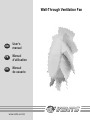
Wall-Through Ventilation Fan

2
READ CAREFULLY AND SAVE THESE INSTRUCTIONS.
EN
WARNING!
READ CAREFULLY AND SAVE THESE INSTRUCTIONS TO REDUCE THE RISK OF FIRE, ELECTRIC SHOCK AND
PERSONAL INJURY.
1. Use the product only in the manner intended by the manufacturer. If you have questions, contact the manufacturer.
2. Before servicing or cleaning the product, switch off the power at the main service panel and lock it to prevent the
power from accidentally being turned on. If the panel cannot be locked securely, fasten a prominent warning device,
such as tag, to it. If the fan is not hard-wired but rather plugged into a 120 Volt outlet, unplug the cord from the
receptacle.
3. Installation work and electrical wiring must be done by qualified person(s) in accordance with all applicable codes
and standards, including fire-rated construction codes and standards.
4. Sufficient air is needed for proper combustion and exhaust of gases through the flue (chimney) of fuel burning
equipment to prevent back drafting. Follow the heating equipment manufacturer's guidelines and safety standards such
as those published by the National Fire Protection Association (NFPA), and the American Society for Heating,
Refrigeration and Air Conditioning Engineers (ASHRAE), and the local code authorities.
5. When cutting or drilling into wall or ceiling, do not damage electrical wiring and other hidden utilities.
6. The exhaust fans must always be vented to outdoors.
7. The fan may have sharp edges. Use caution to avoid being cut when installing and cleaning.
8. The fan must be grounded.
CAUTION!
1. For general ventilation use only. Not for use in fire rated installations. Do not use the fan to exhaust hazardous or
explosive materials and vapors.
2. For interior use only. Mount with the lowest moving parts at least 8 feet (2.5 meters) above the floor or grade level.
3. To avoid the motor damage and noisy and/or unbalanced impeller, keep drywall spray, construction dust, etc. off the
power unit.
4. Prior to installation operations make sure there is no visible damage to the impeller and housing.
Also make sure there are no foreign objects in the fan.
5. Please read specification label on product for further information and requirements.
6. Both the inlet and outlet must have no obstructions for the fan to work properly and be covered by the warranty.
7. When storing the fan keep it in a dry, weather-protected environment in the original packaging. If the fan has been
stored or set in a cold environment, wait 2 hours before connecting it to the power source.

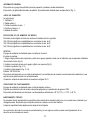
GENERAL
The product described herein is a ventilation for small up to medium-sized domestic premises. The fan and the ventilation fan
grille are made of plastic. The ventilation is designed for through-the-wall mounting, Fig. 1. fan
DELIVERY SET
Box includes:
1. Fan - 1
2. External grille - 1
3. Plastic air duct - 1
4. Screws and anchors - 6
5. User's manual
UNDERSTANDING MODEL NUMBER
The three digit number in all model names indicates the following:
100 (100 mm) means it is used with 4” air duct
125 (125 mm) means it is used with 5” air duct
150 (150 mm) means it is used with 6” air duct
MOUNTING
The ventilation is designed for through-the-wall mounting. fan
Mounting steps:
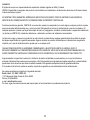
1. Select an installation place for the ventilation kit and drill a round core hole. Its diameter must match the air duct
diameter, Fig. 2.
2. Insert the air duct in the hole and fix it with a mounting foam, Fig. 3.
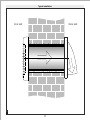
3. Install the fan, Fig. . 4-15
4. Install the external grille, Fig. . 16-19
Input: 120 VAC 60 Hz. The fan is equipped with a power cable with a plug for connection to a standard wall socket or with a
terminal box for direct connection to power supply. Connection to power supply is shown in Fig. . 20-23
OPERATION CONDITIONS
The ventilation kit is rated for continuous operation .
IPX4 rating ensures protection from splash of water for at least 5 minutes.
The fans can be operated at ambient temperatures between +32 F (0 °C) up to 113 F (+45 °C). +
MAINTENANCE
The fan surfaces need to be cleaned of dirt and dust regularly by using a soft, wet cloth and mild detergent.
Do not allow liquids to come in contact with the electric motor!
Wipe the surfaces dry after cleaning.
The product design is constantly being improved, that is why some models can differ slightly from those described in this
manual models.
3

WARRANTY
The product meets standard operating requirements in the North America.
VENTS US warrants to the original purchaser of the product that it will be free from defects in materials or workmanship for a
period of 24 months from the date of original purchase.
THERE ARE NO OTHER WARRANTIES, EXPRESS OR IMPLIED, INCLUDING, BUT NOT LIMITED TO, IMPLIED
WARRANTIES OF MERCHANTABILITY OR FITNESS FOR A PARTICULAR PURPOSE.
During the stated warranty period, VENTS US will, at its option, repair or replace, without charge, any product or part which is
found to be defective under normal use and service. This warranty does not cover (a) normal maintenance and normal service
or (b) any products or parts which have been subject to misuse, negligence, accident, improper maintenance or repair
(other than by VENTS US), faulty installation or installation contrary to recommended installation instructions.
Labor to remove and replace products is not covered.
The duration of any implied warranty is limited to the time period specified for the express warranty.
Some states do not allow limitations on how long an implied warranty lasts, so the above limitation may not apply to you.
VENTS US OBLIGATION TO REPAIR OR REPLACE, AT VENTS US OPTION, SHALL BE THE PURCHASER'S SOLE AND
EXCLUSIVE REMEDY UNDER THIS WARRANTY.
VENTS US SHALL NOT BE LIABLE FOR INCIDENTAL, CONSEQUENTIAL OR SPECIAL DAMAGES ARISING OUT OF OR IN
CONNECTION WITH PRODUCT USE OR PERFORMANCE.
Some states do not allow the exclusion or limitations of incidental or consequential damages, so the above limitation or exclusion
may not apply to you.
This warranty gives you specific legal rights, and you may also have other rights which vary from state to state.
This warranty supersedes all prior warranties.
If proof of sales date is not available, the warranty period is calculated from the production date.
The product can be exchanged at the following address:
Bodor Vents, LLC DBA: VENTS-US
11013 Kenwood Road Cincinnati, Ohio 45242
Phone: (513)348-3853
e-mail: [email protected]
Please follow guidelines in this manual for product problem-free operation.
4
Page is loading ...
Page is loading ...
Page is loading ...
Page is loading ...
Page is loading ...
Page is loading ...

Typical installation
1
11
Outer
wall
Inner
wall

Air duct installation
2
min 3°
3
12
Outer wall
Inner wall
Install the air duct with the minimum slope 3°
downwards to ensure condensate drainage. Fill the
gap between the air duct and the wall with
mounting foam.
Prepare a round hole in the exterior wall of the
building. The hole size and the minimum
recommended distance to a mounting surface,
for example, a wall, ceiling or a window are
shown in the Figure.
min 20"
min 20"
min 20"
100 Kit - DIA (5")
125 Kit - DIA (6")
150 Kit - DIA (7")

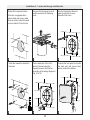
Installation of MA series wall-through ventilation fan
7
4
8
5
13
9
6
Use the back part of the front
panel to mark the four screw
holes. Drill the holes.
Remove the front panel cover to
enable access to the fastening
holes.
Connect the front panel cover with
the back part and secure them with
a screw at the bottom.
Route all the required cables.
If the fan is equipped with a
power cable and a plug, make
sure an electric outlet is located
no more than 9 ft from the fan.
Insert the expansion anchors in
the holes.
Fix the back part of the front
panel to the wall using the
supplied screws. Wire the fan
according to the wiring diagram in
Fig. 20 or 22.

13
10
14
11
15
12
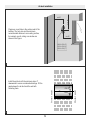
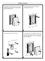
Installation of series wall-through ventilation fanLD
14
Use the back part of the front
panel to mark the 4 screw
holes.Drill the holes.
Remove the front panel cover to
enable access to the fastening
holes.
Connect the front panel cover with
the back part and secure them
with a screw at the bottom.
Route all the required cables.
If the fan is equipped with a
power cable and a plug, make
sure an electric outlet is located
no more than 9 ft from the fan.
Insert the expansion anchors in
the holes.
Fix the back part of the front
panel to the wall using the
supplied screws. Wire the fan
according to the wiring diagram in
Fig. 21 or 23.

Installation of outer hood
15
Disassemble the ventilation hood to ensure access to
the fastening holes. Disconnect and remove the front
part of the ventilation hood.
Insert the expansion anchors in the holes
Fix the back part of the ventilation hood to the wall
using the supplied screws. Secure the hood to the
back plate by pressing the two parts together.
Easy click installation
Use the back part of the hood to mark the four
screw holes. Drill the holes.
18
16
19
17

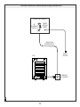
120VAC, 60Hz
POWER SOURCE
QF
AUTOMATIC
SWITCH
GREEN
GROUND
SCREW
HOUSE JUNCTION BOX
EARTH
GROUND
FAN
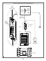
Electrical Connection of MA series wall-through ventilation fan
STANDARD
WALL SOCKET
20
16

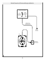
FAN
Electrical Connection of LD series wall-through ventilation fan
21
17
120VAC, 60Hz
POWER SOURCE
QF
AUTOMATIC
SWITCH
GREEN
GROUND
SCREW
HOUSE JUNCTION BOX
STANDARD
WALL SOCKET
EARTH
GROUND

S
JUNCTION
BOX
120VAC, 60Hz
POWER SOURCE
STANDARD
WALL SWITCH
QF
AUTOMATIC
SWITCH
GREEN
GROUND
WIRE
TO FAN
TO S
TO QF
AND
GROUND SCREW
GREEN
GROUND
SCREW
HOUSE JUNCTION BOX
GROUND
FAN
L
N
X
N
L
N
L
~120V 60Hz
X
QF
S
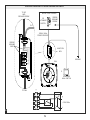
Electrical connection MA series standard wall switch
1g
22
18

S
JUNCTION
BOX
120VAC, 60Hz
POWER SOURCE
STANDARD
WALL SWITCH
QF
AUTOMATIC
SWITCH
GREEN
GROUND
WIRE
TO FAN
TO S
TO QF
AND
GROUND SCREW
GREEN
GROUND
SCREW
HOUSE JUNCTION BOX
GROUND
FAN
L
N
X
N
L
N
L
~120V 60Hz
X
QF
S
Electrical connection LD series standard wall switch
1g
23
19

www.vents-us.com
100
125
150
LD Kit
MA Kit
ACCEPTANCE CERTIFICATE
CERTIFICAT D'ACCEPTATION
CERTIFICADO DE CALIDAD
Date of sale
Date de la vente
Fecha de venta
Manufactured on (date):
Vendu
(nom d'entreprise de commerce, cachet du magasin)
Fabriqué le (date)
Approval mark
Fecha de producion
Signe d'approbation
Marca de verificador
Vendido
(nombre de empresa, timbro o sello)
Sold
(name of trading enterprise, stamp of store)
The fan has been duly certified as serviceable.
Le ventilateur a été certifié comme utilisable.
Este ventilador está certificado para el uso normal.
V-US141EN-02
-
 1
1
-
 2
2
-
 3
3
-
 4
4
-
 5
5
-
 6
6
-
 7
7
-
 8
8
-
 9
9
-
 10
10
-
 11
11
-
 12
12
-
 13
13
-
 14
14
-
 15
15
-
 16
16
-
 17
17
-
 18
18
-
 19
19
-
 20
20


Vents VENTS GK 125 MA Installation guide
- Type
- Installation guide
- This manual is also suitable for
Ask a question and I''ll find the answer in the document
Finding information in a document is now easier with AI
in other languages
Related papers
-
VENTS-US TT SILENT M 125 User manual
-
VENTS-US TT PRO 125 User manual
-
-
-
-
-
-
VENTS-US TT SILENT 125 Operating instructions
-
-
Other documents
-
VENTS-US VK 200 User guide
-
VENTS-US TT 150 User guide
-
VENTS-US VKM 125 User guide
-
-
-
-
-
-
-