Page is loading ...

SC2039002-BN-00 - ENG Page 1 of 24 20121206 –V1
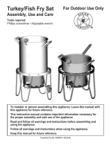
4 in 1 Multi-Function Smoker / Grill / Fryer
Model: SC2039002-BN-00
For Outdoor Use Only
Tools required:
Philips screwdriver / Adjustable wrench
This instruction manual contains important information necessary for the proper
assembly and safe use of the appliance.
Read and follow all warnings and instructions before assembling and using the
appliance.
Follow all warnings and instructions when using the appliance.
Keep this manual for future reference.
This appliance is NOT for frying turkeys.

SC2039002-BN-00 - ENG Page 2 of 24 20121206-V1
DANGER
If you smell gas:
1. SHUT OFF gas to the appliance.
2. EXTINGUISH any open flame.
3. If odor continues, keep away from the appliance and immediately call
your FIRE DEPARTMENT.
Failure to follow these instructions could result in fire or explosion which
could cause property damage, personal injury or death.
DANGER
1. NEVER operate this appliance UNATTENDED.
2. NEVER operate this appliance WITHIN 10 ft (3.0m) of any structure,
combustible material or other gas cylinder.
3. NEVER operate this appliance within 25 ft (7.5m) of any flammable
liquid.
4. NEVER allow oil or grease to get HOTTER than 400°F or 200°C. If the
temperature exceeds 400°F (200°C) or if oil begins to smoke,
IMMEDIATELY turn the burner or gas supply OFF.
5. Heated liquids remain at scalding temperatures long after the cooking
process. NEVER TOUCH cooking appliance UNTIL LIQUIDS HAVE
COOLED to 115°F (45 °C) or less.
6. If a fire should occur, keep away from the appliance and IMMEDIATELY
call your FIRE DEPARTMENT. Do not attempt to extinguish an oil or
grease fire with water.
7. The minimum environmental temperature of this appliance is -21°F
(-10°C).Do not use this appliance under above rated temperature.
Failure to follow these instructions could result in fire, explosion or burn
hazard which could cause property damage, personal injury or death.

SC2039002-BN-00 - ENG Page 3 of 24 20121206-V1
WARNING
Combustion by-products when using this product contain chemicals known to the
State of California to cause cancer, birth defects, or other reproductive harm.
WARNING
This Appliance is NOT intended for commercial use.
WARNING
This Appliance is NOT for Frying Turkeys.
Safety Symbols
The symbols and boxes shown below explain what each heading means. Read and
follow all of the messages found throughout the manual.
DANGER
DANGER: Indicates an imminently hazardous situation which, if not avoided, will
result in death or serious injury.
WARNING
WARNING: Indicates a potentially hazardous situation which, if not avoided, will
result in death or serious injury.
CAUTION
CAUTION: Indicates a potentially hazardous situation or unsafe practice which, if
not avoided, may result in minor or moderate injury.

SC2039002-BN-00 - ENG Page 4 of 24 20121206-V1
WARNING
The installation must conform with local codes or, in the absence of local codes, with
either the National Fuel Gas Code, ANSI
Z223.1/NFPA 54, Natural Gas and Propane
Installation Code, CSA B149.1, or Propane
Storage and Handling Code, B149.2.
This appliance must not be used on or under
any apartment or condominium balcony or
deck.
This appliance shall be used outdoors, and
must not be used in a building, garage or any
other enclosed area.
This appliance is not intended to be installed
in or on a boat and/or recreational vehicles.
Keep appliance at least 10 ft (3m) from any combustible materials and wall. Keep at
least 10 ft (3m) from such materials on the sides and back of appliance, and the
appliance must not be located under overhead unprotected combustible construction.
Never use under balconies made of wood or ANY overhead construction.
Keep the fuel supply hose away from any heated surfaces.
This appliance is NOT intended for commercial use.
The use of alcohol, prescription or non-prescription drugs might impair the consumer’s
ability to properly assemble or safely operate the appliance.
When cooking with oil or grease, have a type BC or ABC fire extinguisher readily
available. In the event of an oil or grease fire DO NOT attempt to extinguish with water.
Immediately call the FIRE DEPARTMENT. A Type BC or ABC fire extinguisher may, in
some circumstances contain the fire.
24”
WARNING: Hose is a trip hazard.

SC2039002-BN-00 - ENG Page 5 of 24 20121206-V1
In the event of rain, snow, hail, sleet or other forms of precipitation while cooking with
oil or grease, cover the cooking vessel immediately and turn off the appliance burners
and gas supply. DO NOT attempt to move the appliance or cooking vessel.
When cooking, the appliance fryer/boiler MUST BE ON A LEVEL, STABLE
NONCOMBUSTIBLE SURFACE in an area clear of combustible material. An asphalt
surface (blacktop) is not acceptable for this purpose.
DO NOT leave the appliance unattended. Keep children and pets away from the
appliance at all times.
Do not place an empty cooking vessel on the appliance while in operation. Use caution
when placing anything in cooking vessel while the appliance is in operation.
Do not move the appliance when in use. Allow the cooking vessel to cool to 115°F
(45°C) before moving or storing.
For outdoor use only. If stored indoors, detach and leave cylinder outdoors.
This appliance is not intended for and should never be used as a heater.
When cooking with oil or grease, the thermometer provided MUST be used. Follow
instructions in this manual for proper installation and use of the thermometer. If the
thermometer supplied with this fryer/boiler has been lost or damaged, a replacement
thermometer must be one specified by the appliance manufacturer.
This appliance will be HOT during and after use. Use insulated oven mitts or gloves for
protection from hot surfaces or splatter from cooking liquids.
If the temperature exceeds 400°F (200°C) or if oil begins to smoke, immediately turn
the burner or gas supply OFF and wait for the temperature to decrease to less than
350°F (175°C) before relighting burner according to this instructions manual.
It is recommended that the cooking vessel not exceed 10QT & 12-3/4” diameter. A
BIGGER VESSEL MAY RESULT IN TIPPING.
Never overfill the cooking vessel with oil, grease or water than specified by vessel
manufacturer instruction. If the vessel doesn’t indicate the maximum fill line, please
refer to following instructions for determining the maximum fill level.
Determining the maximum fill level when using a vessel without a maximum line:
(1) Place the food product in the basket.
(2) Place the food product and holder into the empty vessel.
(3) Fill the vessel with water just until the food product is completely submerged. There
must be a minimum of 3 inch (8 cm) between the water level and top of the vessel.
(4) Remove the food product from the vessel and either mark the water level on the
side of the vessel or measure the amount of water in the vessel.
(5) Remove the water and completely dry the vessel and the food product.
(6) This is the amount of cooking oil the vessel is to be filled with to cook the food
product.
Introduction of water or ice from any source into the oil/grease may cause overflow and
severe burns from hot oil and water splatter. When frying with oil/grease, all food
products MUST be completely THAWED and towel DRIED before being immersed in
the fryer.
Avoid bumping into or impacting the appliance to prevent spillage or splashing of hot
cooking liquid.
Never drop food or accessories into hot cooking liquid. Lower food and accessories
slowly into the cooking liquid in order to prevent splashing or overflow. When removing
food from the appliance care must be taken to avoid burns from hot cooking liquids.

SC2039002-BN-00 - ENG Page 6 of 24 20121206-V1
DANGER
The safety relief valve on the LP tank could activate the releasing of gas and cause
an intense fire with risk of death or serious injury. Therefore, follow instructions below
exactly.
A. Do not store a spare LP-gas cylinder under or near this appliance.
B. Never fill the cylinder beyond 80 percent full.
C. If the instructions in (A) and (B) are not followed exactly, a fire causing death or
serious injury may occur.
If you see, smell, or hear escaping gas, immediately get away from the LP tank /
appliance and call your FIRE DEPARTMENT.
All spare LP tanks must have safety caps installed on the LP tank outlet.
LP Tank Removal, Transport and Storage
Turn OFF control knobs at regulator and LP tank valve. Turn coupling nut
counterclockwise by hand only – DO NOT USE TOOLS TO DISCONNECT. Place dust
cap on cylinder valve outlet whenever the cylinder is not in use. Only install the type of
dust cap on the cylinder valve outlet that is provided with the cylinder valve. Other
types of caps or plugs may result in leakage of propane.
A disconnected LP tank in storage or being transported must
have a safety cap installed as shown. Do not store an LP tank
in enclosed spaces such as a carport, garage, porch, covered
patio or other building. Never leave an LP tank inside a vehicle
which may become overheated by the sun.
Storage of an appliance indoors is permissible only if the
cylinder is disconnected and removed from the appliance.
Cylinder must be stored outdoors out of the reach of children
and must not be stored in a building, garage or any other
enclosed area.
Turn off gas at supply cylinder when not in use.
LP Tank
The LP tank used with your appliance must meet the following requirements:
Purchase LP tanks only with these required measurements: 12”(30.5cm)(diameter) x
18”(45.7cm)(tall) with 20lb.(9kg) capacity maximum.
The LP-gas supply cylinder to be used must be constructed and marked in accordance
with the specifications for LP-gas cylinders of the US Department of Transportation
(DOT) or the National Standard of Canada, CAN/CSA-B339, Cylinders, Spheres and
Tubes for the Transportation of Dangerous Goods.
LP tank valve must have:
Type 1 outlet compatible with regulator or appliance.
Safety relief valve.
UL listed Overfill Protection Device (OPD). This OPD safety
feature is identified by a unique triangular hand wheel. Use
only tanks equipped with this type of valve.
LP tank must be arranged for vapor withdrawal and include collar to
protect LP tank valve.
LP(Liquefied Petroleum Gas)
LP gas is non-toxic, odorless and colorless when produced. For your safety, LP gas
has an odor (similar to rotten eggs) so that it can be smelled.
LP gas is highly flammable and may ignite unexpectedly when mixed with air.

SC2039002-BN-00 - ENG Page 7 of 24 20121206-V1
LP Tank Filling
Use only licensed and experienced dealers.
LP dealer must purge tanks before filling.
Dealer should NEVER fill LP tank more than 80% of LP tank volume. Volume of
propane in tanks will vary by temperature.
A frosted regulator indicates gas overfill. Immediately close LP tank valve and call LP
gas dealer for assistance.
Do not release liquid propane (LP) gas into the atmosphere. This is a hazardous
practice.
To remove gas from LP tank, contact an LP dealer or call a local FIRE DEPARTMENT
for assistance. Check the telephone directory under “GAS Companies” for nearest
certified LP dealers.
LP Tank Exchange
Many retailers that sell appliances offer you the option of replacing your empty LP
tanks through an exchange service, Use only those reputable exchange companies
that inspect, precision fill, test and certify their cylinders. Exchange your tank only for
an OPD safety feature-equipped tanks as described in the “LP Tank” section of this
manual.
Always keep new and exchanged LP tanks in upright position during use, transit or
storage.
Leak test new and exchanged LP tanks BEFORE connecting to appliance.
LP Tank Leak Test
For your safety
Leak test must be repeated each time LP tank is exchanged or
refilled.
Do not smoke during leak test.
Do not use an open flame to check for gas leaks.
Appliance must be leak checked outdoors in well-ventilated area,
away from open flames or sparks.
Use a clean paint brush and 50/50 soap and water solution.
Use mild soap and water. Do not use household cleaning agents. Damage to gas train
components can result.
Brush soapy solution onto all metal seams and entire valve area.
Regulator Hose Assembly Check
Before each use, check to see if there is evidence of abrasion, wear, cuts or leaks. The
hose must be replaced prior to the appliance being put into operation. The
replacement hose assembly must be that specified by the manufacturer.
WARNING
If “growing” bubbles appear, do not use or move the LP tank. Contact an LP gas supplier or
your fire department.

SC2039002-BN-00 - ENG Page 8 of 24 20121206-V1
Connecting Regulator to the LP Tank
1. Place LP tank on a secure, level, and stable surface.
2. Turn control knob to the OFF position.
3. Turn LP tank OFF by turning hand wheel clockwise to a full
stop.
4. Remove the protective cap from the LP tank valve. Always
use cap and strap supplied with valve.
5. Hold regulator, insert nipple (B) into LP tank valve. Hand tighten coupling nut, holding
regulator in a straight line (C) with LP tank valve so as not to cross thread the
connection.
6. Turn the coupling nut clockwise to tighten to a
full solid stop. The regulator will seal on the
back-check feature in the LP tank valve,
resulting in some resistance. An additional
one-half to three quarters turn is required to
complete connection. TIGHTEN BY HAND
ONLY – DO NOT USE TOOLS.
NOTE: If you cannot complete connection,
disconnect regulator and repeat step 5 and 6. If
you are still unable to complete the connection,
do not use this regulator!
Disconnecting Regulator to the LP Tank
1. Turn control knob of regulator to the OFF position.
2. Turn LP tank OFF by turning hand wheel clockwise to a full stop.
3. Turn the coupling nut counterclockwise to loosen the connector. Loose by hand only –
do not use tools.
4. When disconnected, the regulator should be hung on the hook attached to the appliance.
WARNING
Do not insert any tool or foreign object into the valve outlet or safety relief valve. You may
damage the valve and cause a leak. Leaking propane may result in explosion, fire, severe
personal injury, or death.
Never attempt to attach this appliance to the self-contained LP gas system of a camper or
trailer or motor home.
The pressure regulator and hose assembly supplied with the appliance must be the one
used. Replacement pressure regulator and hose assemblies must be those specified by
the manufacturer.
WARNING
Do not use appliance until leak checked.
If leak is detected at any time, STOP.
If you cannot stop a gas leak, immediately close LP tank valve, leave area of appliance,
and call LP gas supplier or your fire department!
Do not use a POL transport plug (A)
(plastic part with external threads)! It
will defeat the safety feature of the
valve.

SC2039002-BN-00 - ENG Page 9 of 24 20121206-V1
Leak Testing Valves, Hoses and Regulator
1. Turn all control knob(s) to OFF.
2. Be sure regulator is tightly connected to LP tanks.
3. Completely open LP tank valve by turning hand wheel counterclockwise. If you hear a
rushing sound, turn gas off immediately. There is a major leak at the connection. Correct
before proceeding.
4. Brush soapy solution onto indicated connections shown below in A and B.
5. If “growing” bubbles appear, there is a leak. Close LP tank valve immediately and
retighten connections. If leaks cannot be stopped, do not try to repair. Call for
replacement parts. Order new parts by giving the serial number, number and name of
items needed to the Customer Service Center at 1 – 888 – 837 – 1380. Use only
replacement parts specified by manufacturer.
6. Always close LP tank valve after performing tank test by turning hand wheel clockwise.
Lighting Instructions
1 Read instructions before lighting.
2 When you are sure there are no leaks, turn cylinder valve and regulator control valve
on hose to the closed position.
3 Reopen cylinder valve fully.
4 Have a standard match, fireplace match or long-nosed propane lighter lit and ready to
place over the burner.
5 Light the burner from the burner top
before opening the gas supply, keeping
hands and face away from open
burner.
6 Place lighter over the burner open,
then slowly open regulator valve until
burner ignites.
7 Adjust the regulator control valve for
desired flame height.
8 When finished using the cooker, turn off
gas cylinder valve first. It will take a few
second for the fire to go out and for the propane gas to “bleed” from the hose and
regulator assembly. After the fire is completely out, turn regulator control valve to the
“OFF” position.
9 To re-light, repeat steps 1 – 8. Always use CAUTION as cooker will be hot.
10 If ignition does not occur in 5 seconds, turn the burner control(s) off, wait 5 minutes, and
repeat the lighting procedure.
Match
Turn regulator clockwise
to open the gas supply
B

SC2039002-BN-00 - ENG Page 10 of 24 20121206-V1
CAUTION
If burner does not light OR if burner flame is accidentally extinguished, turn knob to OFF, wait 5
minutes, try again. If the burner does not ignite with valve open OR if burner flame goes out after
lighting, gas will continue to flow out of the burner and could accidentally ignite with risk of injury.
Burner Flame Check
Light Burner, rotate knob from HIGH to LOW. You should
see a smaller flame in LOW position than seen on HIGH.
Always check flame prior to each use. The air damper (D)
mounted on the back of your burner helps to control the
amount of primary air that mixes with the LP gas. A blue
flame with little or no yellow flame provides the best heat.
Adjust the air damper by turning it clockwise or
counterclockwise until the desired flame is achieved.
Turning LP Cooker Off
Turn all knobs to OFF position, turn LP tank OFF by turning
hand-wheel clockwise to a full stop.
Hose Assembly and Regulator Check
Cleaning and inspection of pressure regulator and hose
assembly prior to use. If there is evidence of abrasion, wear, cuts
or leaks, the hose assembly must be replaced prior to the
appliance being put into operation. The replacement hose
assembly shall be that specified by the manufacturer.
Cleaning the Burner
CAUTION
Check and clean burner / manifold tube for insect nests. A clogged tube can lead to fire beneath
the appliances. Spiders’ nests or wasps’ mud inside the burner may cause fire. If a fire occurs,
immediately turn off gas supply at LP tank valve. (See representative illustration in Fig.1.)
Note: Spiders and small insects can spin webs and build nests inside the burner. This especially
occurs in late summer and fall before frost when spiders are most active. These nests can obstruct
gas flow and cause a fire in and around the burner and orifice. Such a fire can cause operator injury
and serious damage to the appliance.
To help prevent a blockage and ensure full heat output, clean and inspect burner tube often (once or
twice a month). NOTE: Water or air pressure will not normally clear a spider web.
Steps for Cleaning the Burner:
1. Remove brass connector / hose from the burner.
2. Look inside the burner tube for nests, webs, or mud.
3. To remove the above obstructions, use an accessory
FLEXIBLE venture brush or bend a small hook on one
end of a long flexible wire such as the one shown in
one small picture.
4. Inspect and clean the burner if needed.
5. Reattach brass connector to burner.
Fig. 1
Fig. 2

SC2039002-BN-00 - ENG Page 11 of 24 20121206-V1
Cleaning and Maintenance
Keep appliance area clear and free from combustible materials, gasoline and other flammable
vapors and liquids.
Do not block holes in bottom or sides of appliance.
Check burner flames regularly.
Use appliance only in well-ventilated space. NEVER use in enclosed space such as carport,
garage, porch, covered patio, or under ANY overhead construction.
Completely thaw meat and poultry prior to placing in hot oil.
To minimize splattering, dry surfaces of meat and poultry prior to placing in hot oil.
When LP tank is connected to appliance, store outdoors in well-ventilated space and out of
reach of children.
Store appliance indoors ONLY if LP tanks turned off and disconnected, removed form appliance
and stored outdoors.
To keep the appliance clear and free from gasoline and other flammable vapors and liquids.
Not obstructing the flow of combustion and ventilation air.
Keeping the ventilation opening(s) of the cylinder enclosed free and clear from debris.
Clean all cooking surfaces of vessels, aluminum pots and pan with warm, soapy water and a
nylon cleaning pad to avoid oxidation, corrosion and rusting.
Correct care and maintenance will keep your appliance operating smoothly. Clean regularly as
determined by the amount of use. NOTE: Clean the entire appliance each year and tighten all
hardware on a regular basis (1-2 times a year or more depending on usage). Cleaning should be
done where detergents won’t harm patio, lawn or the like.
Suggested Cleaning Materials:
Mild dish washing liquid detergent
Hot water
Nylon Cleaning pad
Paper clip
Component Cleaning:
Burner: Use brush to loosen corrosion from burner exterior. Clean clogged gas port holes
with an open paper clip. Replace corroded or damaged burners that would emit excess gas.
For cooking surfaces like pots and pans: Clean the cooking surface with soapy water and a
nylon cleaning pad.
CAUTION
All cleaning and maintenance should only be done when the appliance is cool and with the fuel supply
turned off at the LP tank. DO NOT clean any part in a self-cleaning oven. The extreme heat will
damage the finish.

SC2039002-BN-00 - ENG Page 12 of 24 20121206-V1
Product Diagram

SC2039002-BN-00 - ENG Page 13 of 24 20121206-V1
Component List
1. Lid
2. Body
3. Bottom Bowl
4. Cooker Stand Body
1a: Lid – 1pc
1b: Air vent – 1pc
Qty:1
Qty:1
Qty:1
5. Cooker Stand Leg
6. Bottom Bowl Leg
7. Spring Coil Handle
8. Thermometer / Nut
Qty:3
Qty:3
Qty:3
8a: Thermometer – 1pc
8b: Nut – 1pc
9. Cooking Grate
10. Short Grate Bracket
11. Long Grate Bracket
12. Charcoal Grate
Qty:2
Qty:3
Qty:3
Qty:1
13. Water Bowl /
Charcoal Bowl
14. Door Assembly
15. Burner and Gas
Regulator
16. Burner Bracket
Qty:2
14a: Door – 1pc
14b: Door Handle -1pc
14c: Lock plate -1pc
15a: Regulator – 1pc
15b: Burner – 1pc
15c: Nut -1pc
Qty:1
1a
1b
15a
15b
15c
14a
14b
14c
8b
8a

SC2039002-BN-00 - ENG Page 14 of 24 20121206-V1
17. 10QT Pot
18. Strainer Basket
19. Basket Handle
20. 6” Thermometer
Qty:1
Qty:1
Qty:1
20a: Thermometer – 1pc
20b: Clip – 1pc
21. Locking Clip
22. Heat Shield
Qty:3
Qty:1
20a
20b

SC2039002-BN-00 - ENG Page 15 of 24 20121206-V1
Hardware List
Item No.
Item name
Diagram
Qty
A
M6X18 Philips Head Flange
Bolt
9
B
M6X10 Philips Head Flange
Bolt
25
C
M5X10 Philips Head Flange
Bolt
8
D
M5 Serrated Flange Nut
4
(1 pc spare)
E
M6 Wing Nut
6
F
M8 Wing Nut
1
(pre-assembled
on thermometer)
G
M5 Locknut
6
H
M5X12 Philips Head bolt
4
(1 pc spare)

SC2039002-BN-00 - ENG Page 16 of 24 20121206-V1
Assembly Instructions:
Step 1- Attach the Basket Handle (19) to Strainer Basket (18) using 3 sets M5x12 Bolts (H)
and M5 Nuts (D).
Step 2- Put the 6” Thermometer (20) and Strainer Basket (18) in the 10QT Pot (17).
18
H
19
D
17
20
18

SC2039002-BN-00 - ENG Page 17 of 24 20121206-V1
Step 3- Assemble the Cooker Stand Legs (5) to Cooker Stand Body (4) using 12 pcs M6x10
Bolts (B).
Step 4- Assemble the Burner and Gas Regulator (15), Burner Bracket (16) and Heat Shield
(22) to Cooker Stand Body (4) using 4 pcs M6x10 Bolts (B) and Nut (This nut is
pre-assembled on the burner).
5
B
5
4
B
15
This nut is pre-assembled
on the burner
16
22
B
B

SC2039002-BN-00 - ENG Page 18 of 24 20121206-V1
Step 5- Assemble the Bottom Bowl Legs (6) and Long Grate Brackets (11) to the Bottom
Bowl (3) using 9 pcs M6x18 Bolts (A) and 6 pcs M6 Wing Nuts (E).
Step 6- Assemble the Locking Clips (21) to the Bottom Bowl (3) using 6 sets of M5x10 Bolts
(C) and M5 Lock Nuts (G).
3
6
6
11
A
A
A
E
21
21
C
C
C
G

SC2039002-BN-00 - ENG Page 19 of 24 20121206-V1
Step 7- Assemble the Door Assembly (14) to the Bottom Bowl (3) using 2 pcs M5x10 Bolts (C).
Step 8- Assemble the Spring coil Handles (7) to Body (2) using 4 pcs M6x10 Bolts (B).
Assemble the Short Grate Brackets (10) to Body (2) using 3 pcs M6x10 Bolts (B).
14
C
7
7
10
B
B
2

SC2039002-BN-00 - ENG Page 20 of 24 20121206-V1
Step 9- Assemble Spring Coil Handle (7) to Lid (1) using 2 pcs M6x10 Bolts (B).
Assemble the Thermometer (8) through the Lid and secure using the supplied M8 Wing Nut
(F). This nut is pre-assembled on the Thermometer.
Step 10- Put the Cooking Grates (9), Water Bowl / Charcoal Bowl (13), Charcoal Grate (12) in the
smoker as shown.
9
13
2
12
2
1
7
8
B
F – This wing nut is
pre-assembled on
the thermometer
/