Page is loading ...

—
MN442 October 2019
October 2019
—
RPM XE
Integral Horsepower AC Motors
Totally Enclosed
Installation and Operating Manual

Any trademarks used in this manual are the property of their respective owners.
Important:
Be sure to check www.baldor.com to download the latest version of this manual in Adobe Acrobat PDF format.
Note! The manufacturer of these products, Baldor Electric Company became ABB Motors and Mechanical Inc. on March 1, 2018.
Nameplates, Declaration of Conformity and other collateral material may contain the company name of Baldor Electric Company and
the brand names of Baldor-Dodge and Baldor-Reliance until such time as all materials have been updated to reflect our new corporate
identity.

iMN442
Table of Contents
Section 1
General Information .................................................... 1-1
Overview ................................................. 1-1
Limited Warranty ........................................... 1-1
Safety Notice ............................................. 1-1
Receiving ................................................ 1-2
Handling .................................................. 1-2
Storage .................................................. 1-3
Removal From Storage ...................................... 1-4
Equipment Marking for IEC Certied Product ..................... 1-4
EMC Compliance Statement for European Union .................. 1-5
Section 2
Installation & Operation ................................................. 2-1
Overview ................................................. 2-1
Location .................................................. 2-1
Mounting Location .......................................... 2-1
Frame Mounting Holes ................................... 2-2
Coupling Selection ...................................... 2-2
Alignment ............................................. 2-2
Doweling & Bolting ...................................... 2-2
Guarding .............................................. 2-2
Power Connection .......................................... 2-3
Grounding ............................................ 2-3
Conduit Box ........................................... 2-4
AC Power ............................................. 2-4
Rotation ............................................. 2-4
Connection Diagrams ....................................... 2-5
Initial Lubrication ........................................... 2-7
First Time Start Up ......................................... 2-7
Coupled Start Up ........................................... 2-8
Jogging and Repeated Starts ................................. 2-8
Hazardous Locations ....................................... 2-8
Selection .............................................. 2-8
Protection Concepts ..................................... 2-9
Repair of Motors used in Hazardous Locations ................... 2-10
Section 3
Maintenance & Troubleshooting .......................................... 3-1
General Inspection .......................................... 3-1
Relubrication & Bearings .................................... 3-1
Relubrication Intervals ....................................... 3-3
Relubrication Procedure ..................................... 3-4
Connection Box Maintenance ................................. 3-4
Troubleshooting Chart ...................................... 3-5
Suggested bearing and winding
RTD setting guidelines for Non−Hazardous Locations ONLY ..... 3-6
Section 4
Information Required Per IEC 60079-0:2017 Ed7 ............................ 4-1
Clause 30.1 (general) ........................................ 4-1
Clause 30.3 (electrical machines .............................. 4-1

ii MN442

General Information 1-1MN442
Section 1
General Information
Overview This manual contains general procedures that apply to Baldor Motor products. Be sure to read and understand
the Safety Notice statements in this manual. For your protection, do not install, operate or attempt to perform
maintenance procedures until you understand the Warning and Caution statements.
A Warning statement indicates a possible unsafe condition that can cause harm to personnel.
A Caution statement indicates a condition that can cause damage to equipment.
Important: This instruction manual is not intended to include a comprehensive listing of all details for all
procedures required for installation, operation and maintenance. This manual describes general
guidelines that apply to most of the motor products shipped by Baldor. If you have a question about a
procedure or are uncertain about any detail, Do Not Proceed. Please contact your Baldor distributor for
more information or clarification.
Before you install, operate or perform maintenance, become familiar with the following:
• NEMA Publication MG-2, Safety Standard for Construction and guide for Selection, Installation and Use of
Electric Motors and Generators
• IEC 60034−1 Electrical and IEC60072−1 Mechanical specications
• NFPA 70
®
National Electrical Code (NEC) and local codes and practices
Limited Warranty
www.baldor.com/support/warranty_standard.asp
Safety Notice: This equipment contains high voltage! Electrical shock can cause serious or fatal injury. Only qualified
personnel should attempt installation, operation and maintenance of electrical equipment. Be sure
that you are completely familiar with NEMA publication MG-2, safety standards for construction and
guide for selection, installation and use of electric motors and generators, the National Electrical Code
and local codes and practices. Unsafe installation or use can cause conditions that lead to serious or
fatal injury. Only qualified personnel should attempt the installation, operation and maintenance of this
equipment.
WARNING: Do not touch electrical connections before you first ensure that power has been disconnected.
Electrical shock can cause serious or fatal injury. Only qualified personnel should attempt the
installation, operation and maintenance of this equipment.
WARNING: Disconnect all electrical power from the motor windings and accessory devices before disassembly of
the motor. Electrical shock can cause serious or fatal injury.
WARNING: Be sure the system is properly grounded before applying power. Do not apply AC power before you
ensure that all grounding instructions have been followed. Electrical shock can cause serious or fatal
injury. National Electrical Code and Local codes must be carefully followed.
WARNING: Avoid extended exposure to machinery with high noise levels. Be sure to wear ear protective devices to
reduce harmful effects to your hearing.
WARNING: Surface temperatures of motor enclosures may reach temperatures which can cause discomfort or
injury to personnel accidentally coming into contact with hot surfaces. When installing, protection
should be provided by the user to protect against accidental contact with hot surfaces. Failure to
observe this precaution could result in bodily injury.
WARNING: This equipment may be connected to other machinery that has rotating parts or parts that are driven by
this equipment. Improper use can cause serious or fatal injury. Only qualified personnel should attempt
to install operate or maintain this equipment.
WARNING: Do not by-pass or disable protective devices or safety guards. Safety features are designed to prevent
damage to personnel or equipment. These devices can only provide protection if they remain operative.
WARNING: Avoid the use of automatic reset devices if the automatic restarting of equipment can be hazardous to
personnel or equipment.
WARNING: Be sure the load is properly coupled to the motor shaft before applying power. The shaft key must be
fully captive by the load device. Improper coupling can cause harm to personnel or equipment if the
load decouples from the shaft during operation.
WARNING: UL Listed motors must only be serviced by UL Approved Authorized Baldor Service Centers if these
motors are to be returned to a hazardous and/or explosive atmosphere.
WARNING: Thermostat contacts automatically reset when the motor has slightly cooled down. To prevent injury or
damage, the control circuit should be designed so that automatic starting of the motor is not possible
when the thermostat resets.
WARNING: Use proper care and procedures that are safe during handling, lifting, installing, operating and
maintaining operations. Improper methods may cause muscle strain or other harm.
WARNING: Before performing any motor maintenance procedure, be sure that the equipment connected to the
motor shaft cannot cause shaft rotation. If the load can cause shaft rotation, disconnect the load from
the motor shaft before maintenance is performed. Unexpected mechanical rotation of the motor parts
can cause injury or motor damage.
Continued on next page.

1-2 General Information MN442
Safety Notice Continued
WARNING: A voltage will be produced at the motor terminals any time the shaft is rotated, whether or not the motor
is connected to a power source.
WARNING: Do not use non UL/CSA listed explosion proof motors in the presence of flammable or combustible
vapors or dust. These motors are not designed for atmospheric conditions that require explosion proof
operation.
WARNING: Motors that are to be used in flammable and/or explosive atmospheres must display the UL label on the
nameplate along with CSA listed logo. Specific service conditions for these motors are defined in NFPA
70 (NEC) Article 500.
WARNING: Guards must be installed for rotating parts such as couplings, pulleys, external fans, and unused shaft
extensions, should be permanently guarded to prevent accidental contact by personnel. Accidental
contact with body parts or clothing can cause serious or fatal injury.
Caution: To prevent premature equipment failure or damage, only qualified maintenance personnel should
perform maintenance.
Caution: Do not over−lubricate motor as this may cause premature bearing failure.
Caution: Do not lift the motor and its driven load by the motor lifting hardware. The motor lifting hardware is
adequate for lifting only the motor. Disconnect the load (gears, pumps, compressors, or other driven
equipment) from the motor shaft before lifting the motor.
Caution: If eye bolts are used for lifting a motor, be sure they are securely tightened. The lifting direction should
not exceed a 20 º angle from the shank of the eye bolt or lifting lug. Excessive lifting angles can cause
damage.
Caution: To prevent equipment damage, be sure that the electrical service is not capable of delivering more than
the maximum motor rated amps listed on the rating plate.
Caution: If a HI POT test (High Potential Insulation test) must be performed, follow the precautions and procedure
in NEMA MG1 and MG2 standards to avoid equipment damage.
Caution: The space heaters are designed to operate at or below the maximum surface temperature stated on the
nameplate. If the marked ambient and/or voltage are exceeded this maximum surface temperature can
be exceeded and can damage the motor windings. If applied in a division 2 or zone 2 environment this
excessive temperature may cause ignition of hazardous materials.
If you have any questions or are uncertain about any statement or procedure, or if you require additional
information please contact your Baldor distributor or an Authorized Baldor Service Center.
Receiving Each Baldor Electric Motor is thoroughly tested at the factory and carefully packaged for shipment. When you
receive your motor, there are several things you should do immediately.
1. Observe the condition of the shipping container and report any damage immediately to the commercial
carrier that delivered your motor.
2. Verify that the part number of the motor you received is the same as the part number listed on your
purchase order.
Handling The motor should be lifted using the lifting lugs or eye bolts provided.
Caution: Do not lift the motor and its driven load by the motor lifting hardware. The motor lifting hardware is
adequate for lifting only the motor. Disconnect the load (gears, pumps, compressors, or other driven
equipment) from the motor shaft before lifting the motor.
1. Use the lugs or eye bolts provided to lift the motor. Never attempt to lift the motor and additional
equipment connected to the motor by this method. The lugs or eye bolts provided are designed to lift only
the motor. Never lift the motor by the motor shaft or the hood of a WPII motor.
2. To avoid condensation inside the motor, do not unpack until the motor has reached room temperature.
(Room temperature is the temperature of the room in which it will be installed). The packing provides
insulation from temperature changes during transportation.
3. If the motor must be mounted to a plate with the driven equipment such as pump, compressor etc., it may
not be possible to lift the motor alone. For this case, the assembly should be lifted by a sling around the
mounting base. The entire assembly can be lifted as an assembly for installation. Do not lift the assembly
using the motor lugs or eye bolts provided. Lugs or eye bolts are designed to lift motor only. If the load is
unbalanced (as with couplings or additional attachments) additional slings or other means must be used
to prevent tipping. In any event, the load must be secure before lifting. If the load is unbalanced (as with
couplings or additional attachments) additional slings or other means must be used to prevent tipping. In
any event, the load must be secure before lifting.

General Information 1-3MN442
Storage Storage requirements for motors and generators that will not be placed in service for at least six months from
date of shipment.
Improper motor storage will result in seriously reduced reliability and failure. An electric motor that does not
experience regular usage while being exposed to normally humid atmospheric conditions is likely to develop
rust in the bearings or rust particles from surrounding surfaces may contaminate the bearings. The electrical
insulation may absorb an excessive amount of moisture leading to the motor winding failure.
A wooden crate “shell” should be constructed to secure the motor during storage. This is similar to an export
box but the sides & top must be secured to the wooden base with lag bolts (not nailed as export boxes are) to
allow opening and reclosing many times without damage to the “shell”.
Minimum resistance of motor winding insulation is 5 Meg ohms or the calculated minimum, which ever is
greater. Minimum resistance is calculated as follows: Rm = kV + 1
where: (Rm is minimum resistance to ground in Meg−Ohms and kV is rated nameplate
voltage dened as Kilo−Volts.)
Example: For a 480VAC rated motor Rm =1.48 meg−ohms (use 5 M Ω).
For a 4160VAC rated motor Rm = 5.16 meg−ohms.
Preparation for Storage
1. Some motors have a shipping brace attached to the shaft to prevent damage during transportation.
The shipping brace, if provided, must be removed and stored for future use. The brace must be reinstalled
to hold the shaft rmly in place against the bearing before the motor is moved.
2. Store in a clean, dry, protected warehouse where control is maintained as follows:
a. Shock or vibration must not exceed 2 mils peak-to-peak maximum at 60 hertz, to prevent the
bearings from brinelling. If shock or vibration exceeds this limit vibration isolation pads must be used.
b. Storage temperatures of 10ºC (50ºF) to 49ºC (120ºF) must be maintained.
c. Relative humidity must not exceed 60%.
d. Motor space heaters (when present) are to be connected and energized whenever there is a possibility
that the storage ambient conditions will reach the dew point. Space heaters are optional.
Note: Remove motor from containers when heaters are energized, reprotect if necessary.
3. Measure and record the resistance of the winding insulation (dielectric withstand) every 30 days of
storage.
a. If motor insulation resistance decreases below the minimum resistance, contact your Baldor District
ofce.
b. Place new desiccant inside the vapor bag and re−seal by taping it closed.
c. If a zipper−closing type bag is used instead of the heat−sealed type bag, zip the bag closed instead
of taping it. Be sure to place new desiccant inside bag after each monthly inspection.
d. Place the shell over the motor and secure with lag bolts.
4. Where motors are mounted to machinery, the mounting must be such that the drains and breathers are
fully operable and are at the lowest point of the motor. Vertical motors must be stored in the vertical
position. Storage environment must be maintained as stated in step 2.
5. Motors with anti−friction bearings are to be greased at the time of going into extended storage with
periodic service as follows:
a. Motors marked “Do Not Lubricate” on the nameplate do not need to be greased before or during
storage.
b. Ball and roller bearing (anti−friction) motor shafts are to be rotated manually every 3 months and
greased every 6 months in accordance with the Maintenance section of this manual.
c. Sleeve bearing (oil lube) motors are drained of oil prior to shipment. The oil reservoirs must be relled
to the indicated level with the specied lubricant, (see Maintenance). The shaft should be rotated
monthly by hand at least 10 to 15 revolutions to distribute oil to bearing surfaces.
d. “Provisions for oil mist lubrication” – These motors are packed with grease. Storage procedures are
the same as paragraph 5b.
e. “Oil Mist Lubricated” – These bearings are protected for temporary storage by a corrosion inhibitor.
If stored for greater than 3 months or outdoor storage is anticipated, connected to the oil mist
system while in storage. If this is not possible, add the amount of grease indicated under “Standard
Condition” in Section 3, then rotate the shaft 15 times by hand.
6. All breather drains are to be fully operable while in storage (drain plugs removed). The motors must be
stored so that the drain is at the lowest point. All breathers and automatic “T” drains must be operable to
allow breathing and draining at points other than through the bearings around the shaft. Vertical motors
should be stored in a safe stable vertical position.
7. Coat all external machined surfaces with a rust preventing material.
An acceptable product for this purpose is Exxon Rust Ban # 392.

1-4 General Information MN442
Non−Regreaseable Motors
Non−regreasable motors with “Do Not Lubricate” on the nameplate should have the motor shaft rotated
15 times to redistribute the grease within the bearing every 3 months or more often.
All Other Motor Types
Before storage, the following procedure must be performed.
1. Remove the grease drain plug, if supplied, (opposite the grease tting) on the bottom of each bracket prior
to lubricating the motor.
2. The motor with regreasable bearing must be greased as instructed in Section 3 of this manual.
3. Replace the grease drain plug after greasing.
4. The motor shaft must be rotated a minimum of 15 times after greasing.
5. Motor Shafts are to be rotated at least 15 revolutions manually every 3 months and additional grease
added every nine months (see Section 3) to each bearing.
6. Bearings are to be greased at the time of removal from storage.
Removal From Storage
1. Remove all packing material.
2. Measure and record the electrical resistance of the winding insulation resistance meter at the time
of removal from storage. The insulation resistance must not be less than 50% from the initial reading
recorded when the motor was placed into storage. A decrease in resistance indicates moisture in the
windings and necessitates electrical or mechanical drying before the motor can be placed into service. If
resistance is low, contact your Baldor District ofce.
3. Regrease the bearings as instructed in Section 3 of this manual.
4. Reinstall the original shipping brace if motor is to be moved. This will hold the shaft rmly against the
bearing and prevent damage during movement.
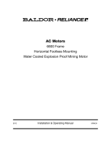
Equipment Marking for IEC Certified Product
IEC certied products have special markings that identify the protection concept and environment
requirements. An example is shown in Figure 1-1.
Figure 1-1 IEC Certified Product Markings
Specific Conditions of Use:
If the motor certicate number is followed by the symbol “X”, this indicates that the motor has specic
conditions of use which are indicated on the certicate. It is necessary to review the product certication
certicate in conjunction with this instruction manual.
Operation On Frequency Converters:
If the motor is evaluated for operation with an adjustable speed drive, the type of converter (for example PWM
for Pulse Width Modulated) and safe speed ranges (for example 0 - 120 Hz) will be specied in the certication
documents or on motor nameplates. It is necessary to consult the adjustable speed drive manual for proper set
up. IECEx Certicates are available online at www.iecex.com
Ex ec MOTOR
MFG. BY BALDOR ELECTRICFORTSMITH,AR72901 USA
Ex ec IICGcTamb ºCto ºC
II 3G IP______
Sira__________________
IECEx__________________
Ex Protection Concept(Ex ec)
GasGroup (IIC)
Temperature Class
ATEX Specic
Markingof
ExplosionProtection
A
TEXEquipment Group and Category (II3)
Type of Atmosphere: G--Gas,D-- Dust(G)
AmbientRange
European ConformityMar
k
PlaceofManufacture

General Information 1-5MN442
Unit Conversions
Inches to Millimeters Inches x 25.4 = mm
Millimeters to Inches mm x .03937 = Inches
Horsepower to Kilowatts Hp x .746 = Kw
Kilowatts to Horsepower Kw x 1.341 = Hp
Pounds to Kilograms Lbs x .454 = Kg
Kilograms to Pounds Kg x 2.205 = Lbs
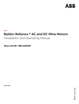
Typical Speed versus Torque Curves are shown in Figure 1-2. For values relative to your specic motor,
consult the motor nameplate marking.
Figure 1-2 Typical Speed versus Torque Curves
0
20
40
60
80
100
120
0 20 40 60 80 100 120 140 160 180 200
Percent Torque
Percent Speed
Load Types
VT
CT
CHP
EMC Compliance Statement for European Union
The motors described in this instruction manual are designed to comply 2004/108/EC and 2014/30/EU. These
motors are commercial in design and not intended for residential use. When used with converters, please
consult converter manufacturers literature regarding recommendations on cable types, cable shielding, cable
shielding termination, connection recommendations and any lters which may be recommended for EMC
compliance. For additional information, consult Baldor MN1383.

1-6 General Information MN442

Installation & Operation 2-1MN442
Section 2
Installation & Operation
Overview Installation should conform to the National Electrical Code as well as local codes and practices. When other
devices are coupled to the motor shaft, be sure to install protective devices to prevent future accidents.
Some protective devices include, coupling, belt guard, chain guard, shaft covers etc. These protect against
accidental contact with moving parts. Machinery that is accessible to personnel should provide further
protection in the form of guard rails, screening, warning signs etc.
Location It is important that motors be installed in locations that are compatible with motor enclosure and ambient
conditions. Improper selection of the motor enclosure and ambient conditions can lead to reduced operating
life of the motor.
For Group I Mining Motors where breather drains are used specied, Breather drain shall be mounted or
protected in installation such that it is guarded from direct impact.”
Proper ventilation for the motor must be provided. Obstructed airow can lead to reduction of motor life.
• Totally Enclosed motors may be installed where dirt, moisture or dust are present and in outdoor
locations.
Severe Duty, enclosed motors are designed for installations with high corrosion or excessive moisture
conditions. These motors should not be placed into an environment where there is the presence of ammable
or combustible vapors, dust or any combustible material, unless specically designed for this type of service.
Hazardous Locations are those where there is a risk of ignition or explosion due to the presence of
combustible gases, vapors, dust, bers, or yings. Facilities requiring special equipment for hazardous
locations are typically classied in accordance with local requirements. In the US market, guidance is provided
by the National Electric Code.
Mounting Location
The motor should be installed in a location compatible with the motor enclosure and specic ambient. To allow
adequate air ow, the following clearances must be maintained between the motor and any obstruction:
Table 2-1 Enclosure Clearance
TEFC / TENV ( IC0141 ) Enclosures All Frames
Fan Cover Air Intake 2” (51mm)
Exhaust Envelope equal to the P Dimension on the motor
dimension sheet
The motor must be securely installed to a rigid foundation or mounting surface to minimize vibration and
maintain alignment between the motor and shaft load. Failure to provide a proper mounting surface may cause
vibration, misalignment and bearing damage.
Foundation caps and sole plates are designed to act as spacers for the equipment they support. If these
devices are used, be sure that they are evenly supported by the foundation or mounting surface.
When installation is complete and accurate alignment of the motor and load is accomplished, the base should
be grouted to the foundation to maintain this alignment.
The standard motor base is designed for horizontal or vertical mounting. Adjustable or sliding rails are
designed for horizontal mounting only. Consult your Baldor distributor or authorized Baldor Service Center for
further information.
Caution: Do not lift the motor and its driven load by the motor lifting hardware. The motor lifting hardware is
adequate for lifting only the motor. Disconnect the load (gears, pumps, compressors, or other driven
equipment) from the motor shaft before lifting the motor.
In the case of assemblies on a common base, any lifting means provided on the motor should not be used
to lift the assembly and base but, rather, the assembly should be lifted by a sling around the base or by other
lifting means provided on the base. Assure lifting in the direction intended in the design of the lifting means.
Likewise, precautions should be taken to prevent hazardous overloads due to deceleration, acceleration or
shock forces.

2-2 Installation & Operation MN442
Coupling Selection
Due to the nature of the starting torque of an RPM-XE motor operating on sine wave power, the coupling
selection is critical for properly applying this motor design. Please consult Application Guide #AG-0102 for the
recommended Dodge couplings.
Maximum Inertia
To ensure successful synchronization, the load inertia should not exceed the values in Table 2-2 below. For
load inertias exceeding these values, contact your Baldor District Ofce. Failure of the RPM-XE motor to
synchronize will lead to extended current draw which is several times the rated full-load value. This current will
cause the motor to overheat and lead to motor failure if unmitigated.
Table 2-2 Load Inertia
Rating (HP @ 60 Hz) Intertia Capability (lb-ft
2)
10 5
15 7
20 8
25 18
30 20
40 32
50 38
60 55
75 67
100 88
125 93
Alignment
Accurate alignment of the motor with the driven equipment is extremely important. The pulley, sprocket,
or gear used in the drive should be located on the shaft as close to the shaft shoulder as possible. It is
recommended to heat the pulley, sprocket, or gear before installing on the motor shaft. Forcibly driving a
unit on the motor shaft will damage the bearings.
i. Direct Coupling
For direct drive, use exible couplings if possible. Consult the drive or equipment manufacturer for more
information. Mechanical vibration and roughness during operation may indicate poor alignment. Use dial
indicators to check alignment. The space between coupling hubs should be maintained as recommended
by the coupling manufacturer.
ii. End-Play Adjustment
The axial position of the motor frame with respect to its load is also extremely important. The standard
motor bearings are not designed for excessive external axial thrust loads. Improper adjustment will cause
failure.
iii. Belt Drive
The RPM XE motor is designed for coupled duty only. If the motor is belted, an adjustable speed drive is
recommended.
Doweling & Bolting
After proper alignment is veried, dowel pins should be inserted through the motor feet into the foundation.
This will maintain the correct motor position should motor removal be required.
(Baldor•Reliance motors are designed for doweling.)
i. Drill dowel holes in diagonally opposite motor feet in the locations provided.
ii. Drill corresponding holes in the foundation.
iii. Ream all holes.
iv. Install proper tting dowels.
v. Mounting bolts must be carefully tightened to prevent changes in alignment.
Use a at washer and lock washer under each nut or bolt head to hold the motor feet secure.
Flanged nuts or bolts may be used as an alternative to washers.

Installation & Operation 2-3MN442
WARNING: Guards must be installed for rotating parts such as couplings, pulleys, external fans, and unused shaft
extensions, should be permanently guarded to prevent accidental contact by personnel.
Accidental contact with body parts or clothing can cause serious or fatal injury.
Guarding Guards must be installed for rotating parts such as couplings, pulleys, external fans, and unused shaft
extensions. This is particularly important where the parts have surface irregularities such as keys, key ways or
set screws. Some satisfactory methods of guarding are:
i. Covering the machine and associated rotating parts with structural or decorative parts of the driven
equipment.
ii. Providing covers for the rotating parts. Covers should be sufciently rigid to maintain adequate guarding
during normal service.
Power Connection
Motor and control wiring, overload protection, disconnects, accessories and grounding should conform to the
National Electrical Code and local codes and practices.
For Ex ec hazardous location motors, it is a specic condition of use that all terminations in a conduit box
be fully insulated. Fully insulated and lugged terminations must be bolted and provided with lock washer to
prevent rotation. Flying leads must be insulated with two full wraps of electrical grade insulating tape or heat
shrink tubing.
Grounding In the USA consult the National Electrical Code, Article 430 for information on grounding of motors and
generators, and Article 250 for general information on grounding. In making the ground connection, the
installer should make certain that there is a solid and permanent metallic connection between the ground point,
the motor or generator terminal housing, and the motor or generator frame. In non−USA locations consult the
appropriate national or local code applicable.
Motors with resilient cushion rings usually must be provided with a bonding conductor across the resilient
member. Some motors are supplied with the bonding conductor on the concealed side of the cushion ring to
protect the bond from damage. Motors with bonded cushion rings should usually be grounded at the time of
installation in accordance with the above recommendations for making ground connections. When motors
with bonded cushion rings are used in multimotor installations employing group fusing or group protection,
the bonding of the cushion ring should be checked to determine that it is adequate for the rating of the branch
circuit over current protective device being used.
There are applications where grounding the exterior parts of a motor or generator may result in greater hazard
by increasing the possibility of a person in the area simultaneously contacting ground and some other nearby
live electrical parts of other ungrounded electrical equipment. In portable equipment it is difcult to be sure that
a positive ground connection is maintained as the equipment is moved, and providing a grounding conductor
may lead to a false sense of security.
Select a motor starter and over current protection suitable for this motor and its application. Consult motor
starter application data as well as the National Electric Code and/or other applicable local codes.
For motors installed in compliance with IEC requirements, the following minimum cross sectional area of the
protective conductors should be used:
Cross sectional area of phase
conductors, S
Minimum cross sectional area of the
corresponding protective conductor, S
p
mm2 mm2
6 6
10 10
16 16
25 25
35 25
50 25
70 35
95 50
120 70
150 70
Equipotential bonding connection shall made using a conductor with a cross-sectional area of at least 4 mm
2
.

2-4 Installation & Operation MN442
Conduit Box For ease of making connections, an oversize conduit box is provided. Most conduit boxes can be rotated
360º in 90º increments. Auxiliary conduit boxes are provided on some motors for accessories such as space
heaters, RTD’s etc.
Figure 2-1 Accessory Connections (when specified)
Leads for each heater are labeled H1 & H2.
(Like numbers should be tied together).
When specified, three thermistors are installed in windings and tied in series.
Leads are labeled TD1 & TD2.
When specified, winding RTDs are installed in windings (2) per phase.
Each set of leads is labeled
1TD1, 1TD2, 1TD3, 2TD1, 2TD2, 2TD3 etc.
* When specified, one bearing RTD is installed in Drive endplate (PUEP), leads
are labeled RTDDE.
* One bearing RTD is installed in Opposite Drive endplate (FREP), leads
are labeled RTDODE.
* Note RTD may have 2−Red/1−White leads; or 2−White/1−Red Lead.
TD1
TD2
Heaters should be connected such that they are not energized
when motor is operating.
AC Power When RPM-XE motors are applied across the line, they are only suitable for 60 Hz (1800 RPM) and 50 Hz (1500
RPM) operation. Motors with ying lead construction must be properly terminated and connected with bolt,
lockwasher and nut wrapped with two full layers of electrical grade tape or heat shrink tubing.
Connect the motor leads as shown on the connection diagram located on the name plate or inside the cover
on the conduit box. Be sure the following guidelines are met:
1. AC power is within +10% of rated voltage with rated frequency. (See motor name plate for ratings).
OR
2. AC power is within +5% of rated frequency with rated voltage.
OR
3. A combined variation in voltage and frequency of +10% (sum of absolute values) of rated values, provided
the frequency variation does not exceed +5% of rated frequency.
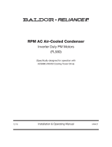
Performance within these voltage and frequency variations are shown in Figure 2-3.
Rotation
All three phase motors are reversible. To reverse the direction of rotation, disconnect and lock out power and
interchange any two of the three line leads for three phase motors.
Adjustable Frequency Power Inverters used to supply adjustable frequency power to motors produce wave
forms with lower order harmonics with voltage spikes superimposed. Turn−to−turn, phase−to−phase, and
ground insulation of stator windings are subject to the resulting dielectric stresses. Suitable precautions should
be taken in the design of these drive systems to minimize the magnitude of these voltage spikes. Consult the
drive instructions for maximum acceptable motor lead lengths, and proper grounding.
Note: Main power leads for CE Marked Motors may be marked U,V,W – for standard congurations,
please consult connection diagrams.
Caution: The space heaters are designed to operate at or below the maximum surface temperature stated on the
nameplate. If the marked ambient and/or voltage are exceeded this maximum surface temperature can
be exceeded and can damage the motor windings. If applied in a Division 2 or Zone 2 environment this
excessive temperature may cause ignition of hazardous materials. Space heaters should be connected
such that they are not energized when motor is operating.

2-5 Installation & Operation MN442
Connection Diagrams

Installation & Operation 2-6MN442
Connection Diagrams Continued

2-7 Installation & Operation MN442
Figure 2-2 Typical Motor Performance Versus Voltage Variations
Initial Lubrication
Baldor•Reliance motors are shipped from the factory with the bearings properly packed with grease and ready
to operate. Where the unit has been subjected to extended storage (6 months or more) the bearings should be
relubricated (regreasable type) prior to starting. When motors are equipped for oil mist lubrication refer to the
instruction manual for installation, operation, and maintenance of oil mist lubrication systems.
First Time Start Up
Be sure that all power to motor and accessories is off. Be sure the motor shaft is disconnected from the load
and will not cause mechanical rotation of the motor shaft.
1. Make sure that the mechanical installation is secure. All bolts and nuts are tightened etc.
2. If motor has been in storage or idle for some time, check winding insulation integrity.
3. Inspect all electrical connections for proper termination, clearance, mechanical strength and electrical
continuity.
4. Be sure all shipping materials and braces (if used) are removed from motor shaft.
5. Manually rotate the motor shaft to ensure that it rotates freely.
6. Replace all panels and covers that were removed during installation.
7. Momentarily apply power and check the direction of rotation of the motor shaft.
8. If motor rotation is wrong, be sure power is off and change the motor lead connections.
Verify rotation direction before you continue.
9. Start the motor and ensure operation is smooth without excessive vibration or noise.
If so, run the motor for 1 hour with no load connected.
10. After 1 hour of operation, disconnect power and connect the load to the motor shaft.
Verify all coupling guards and protective devices are installed. Ensure motor is properly ventilated.
11. If motor is totally enclosed fan−cooled or non−ventilated it is recommended that condensation drain plugs,
if present, be removed. These are located in the lower portion of the end−shields. Totally enclosed fan−
cooled “XT” motors are normally equipped with automatic drains which may be left in place as received.
+20
+15
+10
+5
0
−5
−10
−15
−20
−15 −10 −5 0 +5 +10 +15
Voltage Variations (%)
Changes in Motor Performance (%)
Full -Load
Current
Full -Load
Current
Power
Factor
Power
Factor
Efficiency
Efficiency
Maximum
Torque
Maximum
Torque

Installation & Operation 2-8MN442
Coupled Start Up
This procedure assumes a coupled start up. Also, that the rst time start up procedure was successful.
i. Check the coupling and ensure that all guards and protective devices are installed.
ii. Check that the coupling is properly aligned and not binding.
iii. The rst coupled start up should be with no load. Apply power and verify that the load is not transmitting
excessive vibration back to the motor though the coupling or the foundation.
Vibration should be at an acceptable level.
iv. Run for approximately 1 hour with the driven equipment in an unloaded condition.
The equipment can now be loaded and operated within specied limits. Do not exceed the name plate ratings
for amperes for steady continuous loads.
Jogging and Repeated Starts
Repeated starts and/or jogs generally reduce the life of the motor winding insulation.
A much greater amount of heat is produced by each acceleration or jog than by the same motor under full
load. If it is necessary to repeatedly start or jog the motor, it is advisable to check the application with your
local Baldor distributor or Baldor Service Center.
Heating - Duty rating and maximum ambient temperature are stated on the motor name plate.
Do not exceed these values. If there is any question regarding safe operation, contact your local Baldor
distributor or Baldor Service Center.
Hazardous Locations
Hazardous locations are those where there is a risk of ignition or explosion due to the presence of combustible
gases, vapors, dust, bers or yings.
Selection Facilities requiring special equipment for hazardous locations are typically classied in accordance with local
requirements. In the US market, guidance is provided by the National Electric Code. In international hazardous
location areas, guidance for gas / vapor / mist classication is given in IEC60079−14. This classication
process lets the installer know what equipment is suitable for installation in that environment, and identies
what the maximum safe temperature or temperature class is required.
It is the customer or users responsibility to determine the area classication and select proper equipment.
Areas are classied with respect to risk and exposure to the hazard. In the US market, areas are typically
classied as follows Class, Division, Group and Temperature Class. In some newer installations in the US and
in most international markets, areas are classied in Zones.
Class I Division 2 / Zone 2 Ex ec, [Equipment Protection Level (EPL) Gc ]
This protection concept relies on having no sources of ignition present such as arcing parts or hot surfaces.
For this protection concept, internal temperatures as well as external temperatures are considered. In many
cases, the internal temperatures are higher than the external temperatures and therefore become the limiting
factor in determination of temperature code designation. In these applications, it is very important to use a
motor that has been evaluated thermally for use with an inverter or converter, if variable speed operation is
desired. Thermostats used for Class I Division 2 and Ex ec motors are used to protect the motor only. For
motors using ying lead construction, it is important to use connection lugs and insulate with heat shrink
tubing or a double wrap of insulation grade electrical tape to avoid the risk of spark or ignition.
Class II Division 2 / Zone 22 [Equipment Group III, Equipment Protection Level (EPL) Dc ]
This area classication is one where the risk of exposure to ignitable concentrations of dust are not likely
to occur under normal operating conditions and relies heavily on the housekeeping practices within the
installation.

2-9 Installation & Operation MN442
Sine Wave Power Operation for Division 2 and Zone 1 or 2 and Zone 21 or 22 Hazardous Location.
These motors are designed to operate at or below the maximum surface temperature (or T−Code) stated
on the nameplate. Failure to operate the motor properly can cause this maximum surface temperature to
be exceeded. If applied in a Division 1 or 2 / Zone 1 or 2 and Zone 21 or 22 environment, this excessive
temperature may cause ignition of hazardous materials. Operating the motor at any of the following conditions
can cause the marked surface temperature to be exceeded.
i. Motor load exceeding service factor nameplate value
ii. Ambient temperatures above nameplate value
iii. Voltages above or below nameplate value
iv. Unbalanced voltages
v. Loss of proper ventilation
vi. Altitude above 3300 feet / 1000 meters
vii. Severe duty cycles of repeated starts
viii. Motor stall
ix. Motor reversing
x. Single phase operation of polyphase equipment
xi. Variable frequency operation
Variable Frequency Power Operation for Division 1 or 2 and Zone 1 or 2 and Zone 21 or 22
Hazardous Location (motors with maximum surface temperature listed on the nameplate).
Only motors with nameplates marked for use on inverter (variable frequency) power, and labeled for specic
hazardous areas may be used in those hazardous areas on inverter power. The motor is designed to operate at
or below the maximum surface temperature (or T−Code) stated on the nameplate.
Failure to operate the motor properly can cause this maximum surface temperature to be exceeded.
If applied in a Division 1 or 2 / Zone 1 or 2 and Zone 21 or 22 environment, this excessive temperature may
cause ignition of hazardous materials. Operating the motor at any of the following conditions can cause the
marked surface temperature to be exceeded.
i. Motor load exceeding service factor nameplate value
ii. Ambient temperature above nameplate value
iii. Voltage (at each operating frequency) above or below rated nameplate value
iv. Unbalanced voltages
v. Loss of proper ventilation
vi. Operation outside of the nameplate speed / frequency range
vii. Altitudes above 3300 feet / 1000 meters
viii. Single phase operation of polyphase equipment
ix. Unstable current wave forms
x. Lower than name plate minimum carrier frequency
Thermal Limiting
Thermal limiting devices are temperature sensing control components installed inside the motor to limit the
internal temperature of the motor frame by interrupting the circuit of the holding coil of the magnetic switch or
contactor. They are required for most Division 1 and Zone 1 applications. For Division 2 or Zone 2 applications,
motors should be selected that preclude running temperatures from exceeding the ignition temperatures for
the designated hazardous material. In Division 2 or Zone 2 classied locations, thermal limiting devices should
only be used for winding protection and not considered for limiting all internal motor temperatures to specic
ignition temperatures.
Specific “Conditions of Use” for Ex Equipment or “Schedule of Limitations” for Ex Components:
See Certificate supplied wiht the motor for Specific “Condidtions of Use” for Ex Equipment or
“Schedule of Limitations” for Ex Components.

Installation & Operation 2-10MN442
Specific Information Relative to voltage:
RPM-XE Polyphase Synchronous Motors
The RPM-XE series polyphase synchronous motors are design for operation directly across the line or in
conjunction with a converter. The motors are optimized for the nameplate rating. The optimum Volts and
Current are provided on the nameplate for the optimum rating. When optimum voltage and current is not
supplied to the motor optimum rating may not be obtained. The allowable voltage variation for these motors
when operated across the line on Sine Wave Power is +/- 10%.
When sizing the motor for use with a converter the voltage drop of all components such as lters, long cables,
etc. have to be taken into account. The motor nameplate identies the optimum voltage into the motor. The
allowable voltage variation for these motors when operated from a converter is +/- 5%.
The RPM-AC series polyphase synchronous motors are designed operation at switching / carrier frequencies
of 1.5 kHz or greater for optimum rating.
Repair of Motors used in Hazardous Locations
Repair of hazardous certied motors requires additional information, skill, and care. It is the customer’s
responsibility to select service shops with proper qualications to repair hazardous location motors. Contact
the manufacture for additional repair details. Use only original manufacturer’s parts.
Repair of Dust Ignition Proof Motors − Class II Division 2, Zone 21 and 22.
For Dust Ignition Proof, proper sealing is required. Do not modify the motor construction to add any additional
opening, and ensure that proper sealing is maintained in the connection box and at the shaft seal. Since this
protection method also relies on temperature being maintained, make sure that any rewinding uses the original
electrical designs, including any thermal protection that may be present
Repair of Class I Division 2 and Zone 2 motors
For Division 2 and Zone 2, the internal and external temperatures are of concern. Since this protection method
also relies on temperature being maintained, make sure that any rewinding uses the original electrical designs,
including any thermal protection that may be present. Use only Baldor replacement thermostats, if provided.
/