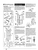
Tools Required for Assembly:
How To Measure Your Finished Opening
3000 Series Bifold Doors
Tools Needed: Phillips Screwdriver, Pencil,
Drill, Measuring Device, 3/16" (5mm) Drill Bit,
3/32" Drill Bit (optional for pilot holes).
Door Layout (4-Door Set)
2 - Door Set
4 - Door Set
Notes:
• Wear Safety Goggles
• Dimensions are in inches
Millimeters are shown in brackets
• Fits normal nished opening height of 80½”
• 2-Door and 4-Door Installations below.
For 4-Door Installations, 2 (two) 2-Door
sets will need to be purchased
FIGURE 1
4-DOOR
MEASURE FROM TOP TO BOTTOM
2 PLACES (HEIGHT)
MEASURE FROM RIGHT TO LEFT
2 PLACES (WIDTH)

Step 3- Mount Hinges
Lay Panels side by side on a at, clean surface
as shown in Figure 7. Push the Panels together
and mount hinges in pre-drilled pilot holes. Mount
Top/Bottom Hinge as shown in Figure 8. Mount
Center Hinge at center of door as shown
in Figure 9.
Note: Only use screws as shown
in gures below and use only
pre-drilled pilot holes.
Step 2- Mount Track
Mount Track to header as shown below. From side
to side, center the Track in the opening. Use 5EA (max)
Long Screws to mount each track. The Upper
Pivot should be on the pivoting side of the opening.
FIGURE 6
4- DOOR
FIGURE 7
Lay Panels Flat
FIGURE 9
Attach Center Hinge
FIGURE 8
Attach Top/Bottom
Hinges

Step 5- Hang Doors by Inserting Bolts into Mount Plates
First insert the bolt in the Upper Pivot into the Long Mount Plate and lock into place by rotating the nylon arm as
shown in Figures 12 & 13. Next, insert the bolt in the roller into the Short Mount Plate and lock the nylon arm.
Step 4- Fasten Mount Plates
Fasten Mount Plates as shown below. Mount plates according to the direction of door swing; right swing or left
swing as shown in Figures 10 & 11 below. It may be helpful to mark the mount plate holes with a pencil and using
a 3/32” drill bit, drill a 1 1/8” deep pilot hole before inserting screws. Note: Make sure the nylon locking arm is on
the back of the door.
d
FIGURE 10 - Right Swing
FIGURE 11 - Left Swing
FIGURE 12
Bolts Into
Mount Plates
FIGURE 13
Rotate Nylon Arm
To Lock

Step 6- Mount Lower Jamb Pivot
Use a Phillips screwdriver to adjust the Lower Jamb Pivot to the position shown in Figure 14. Mount the Lower
Jamb Pivot by placing it directly under the Track on the pivot side as shown in Figures 14 & 15 below. Fasten
with 1 EA Long Screw in the slot rst to allow adjustment up and down to give clearance between Lower Jamb
Pivot and the bottom of the door as shown in Figure 16. Add 2 EA Long Screws to the holes in the Lower
Jamb Pivot once adjustments are nal.
Step 7- Attach at Bottom Pivot
Attach the Bottom Pivot into the Lower Jamb Pivot as shown in Figure 16 below by depressing the spring-loaded tab
on the lower jamb pivot and inserting the tab on the bottom pivot into the hole in the lower jamb pivot. Note: Make
sure and leave 1/8” clearance between the top of the screw head and the bottom pivot for proper operation. (See
Step 8, Check Operation, Make Adjustments to adjust clearance.)
FIGURE 14
Use Phillips
Screwdriver To Adjust
FIGURE 16
Attach At Bottom Pivot
FIGURE 15
Mount Lower
Jamb Pivot

Step 8-
Check Operation,
Make Adjustments
If necessary use the Wrench supplied to
adjust the bolts in the Upper Pivot and
Roller to assure the BiFold door set is
hanging square in the opening. The
Lower Jamb Pivot can be adjusted with
a Phillips screwdriver. Arrows in Figure 17
below show directions of adjustments.
Step 9- Attach Fascia (& Fascia Block for 4-Door Installs)
For 2-Door Installs: Attach Fascia to Track by removing the tape backing and pushing against track as shown in
Figure 18. Cut Fascia to t if necessary. (Cut with Fascia front up.)
U pper
Pivot
Lower Jamb
Pivot
Rollers
FIGURE 17
Areas of
Adjustment
FIGURE 18
Attach 2- Door
Fascia

For 4- Door Installs: Attach each Fascia to the upper corner of the Track by removing the tape backing and
pushing against track as shown in Figure 19. Cut Fascia if necessary. (Cut with Fascia front up.) Place Fascia
Block over the gap at the center of the opening.
Step 10- Attach The Pull
Attach the Pull to the inside stile of the non-pivoting door panel as shown in
Figure 1. Drill a 3/16” (5mm) diameter hole 36” from the bottom of the door
and 1 ½” from the vertical edge of the stile as shown in Figure 1. Attach the
Pull with the Machine Screw as shown in Figure 20 below. Note: It is
best to drill from the front of the door to the back.
FIGURE 19
Attach 4- Door
Fascia
FIGURE 20
Attach Pull

Contents (2 Door Set)
Step 1- Prepare Track for Mounting
Insert components as shown in Figure 2
for 4-Door set or as in Figure 4 for 2-Door
set. The Upper Pivot may need to be loosened
in order to attach to the track. If so, loosen
the screw with a Phillips screwdriver and
if necessary loosen the bolt with the
included wrench just enough to slide the
Upper Pivot onto track. Tighten Upper Pivot
with a Phillips screwdriver as shown in
Figure 5.
For 4-Door set only, replace the
Small Spring with the Long Spring
in the Snugger as shown in Figure 2
Note: Insert parts before
mounting track to header.
2X Panels 1X Fascia
1X Upper Pivot1X Bottom Pivot1X Lower Jamb Pivot
1X Roller
1X Track
22X Long Screw 8X Short Screw 1X Machine Screw (Pull)
1X Center Hinge 2X Top/Bottom Hinge
1X Long Spring
(for 4-Door Installation)
1X Wrench
1X Long Mount Plate 1X Short Mount Plate 1X Snugger 1X Pull
1X Fascia Block
(for 4 - Door Installation)
FIGURE 2
4- Door
FIGURE 3
Side View
FIGURE 4
2- Door
FIGURE 5
Upper Pivot Location
-
 1
1
-
 2
2
-
 3
3
-
 4
4
-
 5
5
-
 6
6
-
 7
7
Ask a question and I''ll find the answer in the document
Finding information in a document is now easier with AI
Related papers
Other documents
-
ReliaBilt 447266 Installation guide
-
 Steves & Sons 302742562 Installation guide
-
ReliaBilt 240709 Installation guide
-
 Kimberly Bay DSVI36 Operating instructions
-
Pinecroft 861720 Installation guide
-
Unbranded 22086215 Operating instructions
-
LTL Home Products 583242 User manual
-
 Pinecroft SEALL24 Installation guide
-
MCE Freedom MRL-MB and MR Elevators User manual
-
JELD-WEN JW101100003 Installation guide


