Page is loading ...

Branch Office Wireless Networking
Symbol Wireless Switch
Quick Installation Guide
WS 2000 Solution (802.11 b)

WS 2000 Quick Installation Guide
2
© 2004 Symbol Technologies, Inc. All rights reserved.
No part of this publication can be modified or adapted in any way, for any purposes without permission in writing from Symbol Technologies
(Symbol). The material in this manual is subject to change without notice. Symbol reserves the right to make changes to any product to
improve reliability, function, or design.
Symbol does not assume any product liability arising out of, or in connection with, the application or use of any product, circuit, or
application described herein.
No license is granted, either expressly or by implication, estoppel, or otherwise under any Symbol Technologies, Inc., intellectual property
rights. No license is granted, either expressly or by implication, estoppel, or otherwise under any patent right or patent, covering or relating
to any combination, system, apparatus, machine, material, method, or process in which Symbol products might be used. An implied
license exists only for equipment, circuits, and subsystems contained in Symbol products.
Symbol, the Symbol logo, and Spectrum24 are registered trademarks of Symbol Technologies, Inc. Other product names mentioned in this
manual may be trademarks or registered trademarks of their respective companies and are hereby acknowledged.
Symbol Technologies, Inc.
One Symbol Plaza
Holtsville, N.Y. 11742-1300
http://www.symbol.com
Patents
This product is covered by one or more of the following U.S. and foreign Patents: U.S. Patent No.
4,593,186 4,603,262; 4,607,156; 4,652,750; 4,673,805; 4,736,095; 4,758,717; 4,760,248; 4,806,742; 4,816,660; 4,845,350;
4,896,026; 4,897,532; 4,923,281; 4,933,538; 4,992,717; 5,015,833; 5,017,765; 5,021,641; 5,029,183; 5,047,617; 5,103,461;
5,113,445; 5,130,520; 5,140,144; 5,142,550; 5,149,950; 5,157,687; 5,168,148; 5,168,149; 5,180,904; 5,216,232; 5,229,591;
5,230,088; 5,235,167; 5,243,655; 5,247,162; 5,250,791; 5,250,792; 5,260,553; 5,262,627; 5,262,628; 5,266,787; 5,278,398;
5,280,162; 5,280,163; 5,280,164; 5,280,498; 5,304,786; 5,304,788; 5,306,900; 5,324,924; 5,337,361; 5,367,151; 5,373,148;
5,378,882; 5,396,053; 5,396,055; 5,399,846; 5,408,081; 5,410,139; 5,410,140; 5,412,198; 5,418,812; 5,420,411; 5,436,440;
5,444,231; 5,449,891; 5,449,893; 5,468,949; 5,471,042; 5,478,998; 5,479,000; 5,479,002; 5,479,441; 5,504,322; 5,519,577;
5,528,621; 5,532,469; 5,543,610; 5,545,889; 5,552,592; 5,557,093; 5,578,810; 5,581,070; 5,589,679; 5,589,680; 5,608,202;
5,612,531; 5,619,028; 5,627,359; 5,637,852; 5,664,229; 5,668,803; 5,675,139; 5,693,929; 5,698,835; 5,705,800; 5,714,746;
5,723,851; 5,734,152; 5,734,153; 5,742,043; 5,745,794; 5,754,587; 5,762,516; 5,763,863; 5,767,500; 5,789,728; 5,789,731;
5,808,287; 5,811,785; 5,811,787; 5,815,811; 5,821,519; 5,821,520; 5,823,812; 5,828,050; 5,848,064; 5,850,078; 5,861,615;
5,874,720; 5,875,415; 5,900,617; 5,902,989; 5,907,146; 5,912,450; 5,914,478; 5,917,173; 5,920,059; 5,923,025; 5,929,420;
5,945,658; 5,945,659; 5,946,194; 5,959,285; 6,002,918; 6,021,947; 6,029,894 6,031,830; 6,036,098; 6,047,892; 6,050,491;
6,053,413; 6,056,200; 6,065,678; 6,067,297; 6,082,621; 6,084,528; 6,088,482; 6,092,725; 6,101,483; 6,102,293; 6,104,620;
6,114,712; 6,115,678; 6,119,944; 6,123,265; 6,131,814; 6,138,180; 6,142,379; 6,172,478; 6,176,428; 6,178,426; 6,186,400;
6,188,681; 6,209,788; 6,209,789; 6,216,951; 6,220,514; 6,243,447; 6,244,513; 6,247,647; 6,308,061; 6,250,551; 6,295,031;
6,308,061; 6,308,892; 6,321,990; 6,328,213; 6,330,244; 6,336,587; 6,340,114; 6,340,115; 6,340,119; 6,348,773; D305,885;
D341,584; D344,501; D359,483; D362,453; D363,700; D363,918; D370,478; D383,124; D391,250; D405,077; D406,581;
D414,171; D414,172; D418,500; D419,548; D423,468; D424,035; D430,158; D430,159; D431,562; D436,104.
Invention No. 55,358; 62,539; 69,060; 69,187 (Taiwan); No. 1,601,796; 1,907,875; 1,955,269 (Japan);
European Patent 367,299; 414,281; 367,300; 367,298; UK 2,072,832; France 81/03938; Italy 1,138,713 rev. 07/04

3
Document Conventions
The following icon conventions are used throughout this document.
Indicates tips, hints, and special requirements.
Care is required. Disregarding cautions can cause data loss or
equipment damage.
Indicates a potentially dangerous condition or procedure
that only Symbol-trained personnel should attempt to
correct or perform.

Contents
To the Installer 6
Verifying Package Contents . . . . . . . . . . . . . . . . . . . . . . . . . . . . . . . . . . . . . . . . . . . . . 7
Symbol Branch Office Wireless Switch Solution 8
Introduction . . . . . . . . . . . . . . . . . . . . . . . . . . . . . . . . . . . . . . . . . . . . . . . . . . . . . . . . . 8
WS 2000 Wireless Switch Description . . . . . . . . . . . . . . . . . . . . . . . . . . . . . . . . . . . . 9
AP 100 Access Port Description . . . . . . . . . . . . . . . . . . . . . . . . . . . . . . . . . . . . . . . . 11
Installing the Branch Office
Wireless Switch Solution 13
The Installation Process . . . . . . . . . . . . . . . . . . . . . . . . . . . . . . . . . . . . . . . . . . . . . . 13
Warnings . . . . . . . . . . . . . . . . . . . . . . . . . . . . . . . . . . . . . . . . . . . . . . . . . . . . . . . . . . 14
Installing the WS 2000 Wireless Switch . . . . . . . . . . . . . . . . . . . . . . . . . . . . . . . . . 15
Installing the AP 100 Access Port . . . . . . . . . . . . . . . . . . . . . . . . . . . . . . . . . . . . . . . 23

5
Configuring the WS 2000 Wireless Switch 27
Getting Started with the WS 2000 Wireless Switch. . . . . . . . . . . . . . . . . . . . . . . . . 27
Step 1: Setting up Administrative Communication to the Switch . . . . . . . . . . . . . . . 28
Step 2: Setting the Basic Switch Settings . . . . . . . . . . . . . . . . . . . . . . . . . . . . . . . . 30
Step 3: Configuring the LAN Interface . . . . . . . . . . . . . . . . . . . . . . . . . . . . . . . . . . . 31
Step 4: Configuring Subnet1 . . . . . . . . . . . . . . . . . . . . . . . . . . . . . . . . . . . . . . . . . . . 33
Step 5: Configuring the WAN Interface . . . . . . . . . . . . . . . . . . . . . . . . . . . . . . . . . . 34
Step 6: Enabling Wireless LANs (WLANs) . . . . . . . . . . . . . . . . . . . . . . . . . . . . . . . . 37
Step 7: Configuring WLAN Security . . . . . . . . . . . . . . . . . . . . . . . . . . . . . . . . . . . . . 39
Step 8: Testing Connectivity . . . . . . . . . . . . . . . . . . . . . . . . . . . . . . . . . . . . . . . . . . . 41
Where to Go from Here? . . . . . . . . . . . . . . . . . . . . . . . . . . . . . . . . . . . . . . . . . . . . . . 42

1
To the Installer
This guide is intended to assist the technician responsible for installing the WS 2000 Wireless
Switch and the AP 100 802.11b Access Port and get the system to a known working
configuration. It assumes that the technician is familiar with basic Ethernet LAN-based
networking concepts. This guide provides specifications, procedures, and guidelines to use
during the installation process. It does not give site-specific installation instructions.
Before operating any equipment, review this document for any hazards associated with
installation and use of the device. Also, review standard practices for preventing accidents.

To the Installer
7
1.1 Verifying Package Contents
Inspect the package contents and report any missing or damaged items to a sales representative. This
system ships in a large box containing two smaller boxes, one for the WS 2000 Wireless Switch and
one for the AP 100 Access Port. These packages should contain the following:
WS 2000 Wireless Switch Parts AP 100 Access Port Parts
• WS 2000 Wireless Switch • AP 100 Access Port assembly
• Clear snap-on face plate • Surface-mount assembly
• Power supply • Mounting anchors
• Line cord • Mounting screws
• Ethernet CAT-5 patch cable (1) • Surface-mount badge
• Rubber feet for desk-mount option • Surface-mount cover
• Rubber plugs for bottom of housing
(4) (already assembled
• Surface-mount light pipe screw
• Ceiling-mount grommet
• Rubber plug for CompactFlash® slot
(already installed in port)
• Ceiling-mount badge
• Ceiling-mount light pipe screw
• Product Documentation CD
Other Parts
• WS 2000/AP 100 System Installation
Guide (this document)

2
Symbol Branch Office
Wireless Switch Solution
2.1 Introduction
The Branch Office Wireless Switch Solution provides both a complete wireless for the enterprise
branch office and small-medium businesses. The WS 2000 Wireless Switch can connect directly
to a cable or DSL modem, and can also connect to other wide-area networks through a Layer 2
or 3 device (such as a switch or router). The AP 100 802.11b Access Port provides area RF
coverage to 802.11b wireless network devices. The AP 100 Access Port includes different
installation options, allowing best placement for optimum range.

Symbol Branch Office Wireless Switch Solu-
9
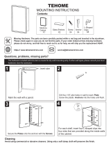
2.2 WS 2000 Wireless Switch Description
The WS 2000 Wireless Switch has the following features:
• One WAN port for connection to a DSL modem, cable modem, or any other Layer 2/3
network device.
• Six LAN ports—four provide 802.3af Power over Ethernet (PoE) support, and the other two
do not provide power. Each port has two LEDs, one indicating the speed of the transmission
(10 Mbit/sec. or 100 Mbit/sec.), the other indicating whether there is activity on the port.
• A serial port for direct access to the command-line interface from a PC. Use a DB-9 female
to female null modem cable to connect to this port.
• A CompactFlash® slot provides storage and delivery of mobile applications.
The WS 2000 offers the power and cost-efficiencies of second-generation wireless networking.
Intelligence previously distributed and duplicated throughout first-generation access point-based
wireless LANs is centralized and aggregated in the WS 2000 Wireless Switch, delivering
unprecedented power and control, and reduced deployment and management costs.
WS 2000 offers enterprise class security (802.11i, site-to-site IPSec VPN), integrated Gateway (NAT,
DHCO, Firewall), public/private network segmentation, and 802.11a/b/g standards support.
Rubber Plug for
CompactFlash Slo
t
Clear Face Plate
WAN Port
2 LAN (RJ-45) Ports
Without Power
4 LAN (RJ-45) Ports
With Power
AC Power Connection
Serial Port
Power LED
CompactFlash Slot
®
®

WS 2000 Quick Installation Guide
10
2.2.1 Technical Specifications
Physical Specifications Power Specifications
Width 286 mm (11.26 in.) Max Power Consumption 90-256VAC, 47-63 Hz, 3A
Height 45 mm (1.75 in.) Operating Voltage 48VDC
Depth 203 mm (7.99 in.) Operating Current 1A Peak Current 1.6A
Weight 0.64 kg
Environmental Specifications
Operating Temperature 0°C to 40°C (32°F to 104°F)
Storage Temperature -40°C to 70°C (-40°F to 158°F)
Operating Humidity 5% to 95% Non-condensing
Storage Humidity 5% to 95% Non-condensing
Operating Altitude 2.4 km (1.49 mi.)
Storage Altitude 4.6 km (2.86 mi.)

Symbol Branch Office Wireless Switch Solu-
11
2.3 AP 100 Access Port Description
The AP 100 Access Port provides the power of IEEE 802.11b Wi-Fi® compatibility to the wireless
LAN. The integrated (internal) 3.5 dBi omni-directional cross-polarized diversity antenna provides
strong wireless coverage, regardless of how the Access Port is mounted. The AP 100 Access Port
receives its firmware from the WS 2000 Wireless Switch, so the time-consuming process of loading
traditional access point firmware is eliminated.
The compact design allows installation on desktops, walls, above ceilings, or beneath ceilings. The
standard mounting base allows securing of the unit to most surfaces with two screws. The above-
ceiling mounting option secures the unit to the ceiling using the ceiling-mount light pipe screw.
Regardless of where the AP 100 Access Port is installed, LED lights are easily visible, providing visual
feedback on the state of the Access Port.
The AP 100 Access Port receives power and transfers data through the Ethernet cable using 802.3af-
compliant power from the wireless switch. No power supply or additional power source is necessary.
Surface-Mount Cover
Surface-Mount
Branding Badge
Access Port
Surface-Mount
Assembly

WS 2000 Quick Installation Guide
12
2.3.1 Technical Specifications
Physical Specifications Power Specifications
Height
• without mounting hardware
• with mounting hardware
78.7 mm (3.10 in.)
152.4 mm (2.04 in.)
Operating Voltage
•typical
• range
48VDC
36VDC to 57VDC
Diameter
• without mounting hardware
• with mounting hardware
51.8 mm (6.0 in.)
155.4 mm (6.12 in.)
Operating Current 10mA to 150mA
Weight 0.36 kg (13 oz.) Peak Current 250mA
Environmental Specifications
Operating Temperature -20°C to 50°C (-4°F to 122°F)
Operating Humidity 5% to 95%
Storage Temperature -40°C to 70°C (-40°F to 158°F)
Altitude 2.4 km (operating max)
4.6 km (storage max)
Drop 0.8 meters (31.50 in.) to concrete
Electrostatic Discharge +/-15kV (air discharge)
+/-8kV (contact discharge)

3
Installing the Branch Office
Wireless Switch Solution
3.1 The Installation Process
The WS 2000 Wireless Switch can operate in various locations, allowing placement in most
environments. The basic installation steps are:
1. Select a site (desk, wall, or rack) for installation of the wireless switch.
2. Install the switch in the selected location using the instructions specifically for that
location type, found in Section 3.3, Installing the WS 2000 Wireless Switch.
Connect the wireless switch to the power supply early in the
installation process for easy access to the connector; however, do
not plug the power supply into a power source before installation
is complete.

WS 2000 Quick Installation Guide
14
3. Lock the device to desk, wall, or rack using the lock port on the switch.
4. Install the Access Port in the selected location using the instructions specifically for that
location type, found in Section 3.4, Installing the AP 100 Access Port.
5. Plug the WAN and LAN (Access Port) connections into the switch.
6. Plug the wireless switch into the wall power socket.
7. See Chapter 4, Configuring the WS 2000 Wireless Switch for information on how to
configure the switch for your network and devices.
3.2 Warnings
Before installing and operating any equipment, review this document for any hazards
associated with installation and use of the device. Also, review standard practices for
preventing accidents.
• Only trained and qualified personnel should install this equipment.
• Read all installation instructions and site survey reports and verify correct equipment
installation before connecting the system to its power source.
• Remove any jewelry (rings, watches, necklaces, etc.) while installing this equipment.
• Install this equipment in racks with appropriate dimensions and weight allowances.
• Verify that racks are anchored and do not install in a way that can cause the equipment to
tip over and break away from its mountings. Damage to the devices or bodily injury can occur
from equipment that was not appropriately mounted and secured.
• Verify the unit is grounded before connecting to the power source. Connect all power cords
to a properly wired and grounded electrical circuit.
• Verify that any devices connected to this unit are properly wired and grounded.
• Verify that connecting power circuits have appropriate overload protection.
• Attach only approved power cords and cables to the devices.
• Verify that the power connector is accessible at all times during the operation of the
equipment.
• Verify that the power circuit for the unit is grounded, can provide the required power, and is
not overloaded.
• Do not work with equipment power circuits in dimly lit spaces.

Installing the Branch Office Wireless Switch
15
• Do not install this equipment or work with its power circuits during thunderstorms or
weather conditions where power surges can exist.
• Verify that there is adequate ventilation around the devices and that ambient temperatures
meet equipment operation specifications.
• Verify uninterruptible power sources—install the socket nearby and easily accessible to the
equipment.
• For equipment that needs to be plugged in, position equipment near an easily accessible
socket-outlet.
• For above-ceiling installations, install unit only in plenum-rated ceilings.
• Do not include the clear plastic surface-mount cover or assembly for above-ceiling
installations. Refer to “Suspended Ceiling Tile (Plenum) Mounting” on page 25 for above-
ceiling mounting instructions.
3.3 Installing the WS 2000 Wireless Switch
3.3.1 Selecting a Site for Installation
The WS 2000 Wireless Switch can be installed on a flat surface, on a wall, or in a rack. In selecting
a site, the installer should verify that the location has access to:
• A grounded outlet—preferably one that has surge protection or is protected by a
uninterruptible power supply (UPS)
• The WAN connection for the switch (whether a modem, router, switch, or hub)
(The wireless switch comes with a 6 ft. (1.829 m) patch cable for this purpose, but the
installer is not required to use either that cable or stay within that distance.)
• The LAN connections for this switch (whether Access Port, switch, hub, or computer)
Ensure that this location meets optimal temperature and environmental requirements for the
operation of this device (see Section 2.2.1, Technical Specifications).
3.3.2 Desk Mounting
The desk-mount option uses rubber feet that allow the unit to sit on most flat surfaces. The four round
rubber feet can be found in the WS 2000 Wireless Switch (main) box.
1. Turn the switch upside down so that the side with the power connector is facing up.
2. Snap the clear face plate (in the WS 2000 main box) onto the front-right side of the switch.

WS 2000 Quick Installation Guide
16
3. Connect the power supply to the switch as shown in the diagram.
Do not attach the power supply to the wall outlet until the
installation of the switch is complete.
4. Remove the backings from the four rubber feet and stick them to the switch on the four
circles, as shown. The feet are right next to the four plugs.
5. Return the switch to the upright position in the place where you wish it to sit, ensuring that
it is sitting evenly on all four rubber feet.
6. Connect the power supply to the wall outlet.
3.3.3 Wall Mounting
The wall-mount bracket option secures the unit to most walls using the four screws included in the
mounting accessories box. The wall-mounting accessories are sold separately from the wireless
switch (Part No. KT-MTG-WS-2000-WW).
1. Remove the protective rubber plugs from the switch as shown.
Power Plug Connector
Rubber Plugs

Installing the Branch Office Wireless Switch
17
To snap into the wall-mount bracket, the protective rubber plugs
must be removed.
2. Using the screws and wall anchors supplied in the mounting accessories box, attach the
wall-mount bracket to the wall as shown.
Align the RJ-45 ports on the switch with the embossed port symbols on the front
of the wall-mount bracket.
3. Connect the power supply to the switch, but not to the wall outlet.
Do not attach the power supply to the wall outlet until
installation of the switch is complete.
4. Align the holes on the bottom of the switch (where the plugs used to be) with the plastic
guides on the mounting bracket (circled in diagram below).
Wall
Embossed
Port Symbols

WS 2000 Quick Installation Guide
18
5. Push the switch into place on the bracket. A snap indicates that the switch is securely
attached to the bracket.
6. Connect the power supply to the wall outlet.
The wall-mount bracket is designed to allow threading of cables underneath the
bracket. There is space underneath the wall-mount bracket to hold cables.
Cables can be placed above, between, or below the attachment points.
3.3.4 Rack Mounting
The rack-mounting option provides a 1U bracket to the switch allowing it to be mounted in a standard
rack. Rack-mounting accessories are sold separately from the wireless switch (Part No. KT-MTG-WS-
2000-WW).
1. Connect the power supply to the connector on the bottom-rear of the switch.
Do not attach the power supply to the wall outlet until
installation of the switch is complete.
2. Attach the 1U bracket to the rack using four of the six screws provided in the mounting
accessories box.

Installing the Branch Office Wireless Switch
19
3. With the front of the switch tilted slightly upward, slide the back of the switch between the
guides at the rear of the bracket, until the two retaining clips slide into slots in the back of
the switch, as shown.
4. Set the front side of the switch down on to the bracket making sure that the locator tabs in
the front of the bracket slide into the two slots on the bottom front of the switch.
5. Attach the rack bezel to the bracket. To do this, tilt the bezel forward and place the T-shaped
tabs on the lower edge of the bezel just behind the lip on the front of the rack bracket. (There
are two holes in the lip where they attach.) Pull the bezel forward slightly and the
T-tabs should lock into place.
6. Using the remaining two screws provided in the mounting accessories box and attach the
bezel to the rack bracket.
Guides
Retaining Clips
Locator Tabs
Attach to Rack
Front
Back
Guide
Front
see Detail A
Detail A
T-shaped tab

WS 2000 Quick Installation Guide
20
7. Connect the power supply to the wall outlet and turn on the switch when appropriate.
3.3.5 Securing the Network Switch
The WS 2000 Wireless Switch comes with a lock port that is compatible with most locking systems.
The lock port is on the rear of the switch, opposite the power connector. In order to have clear access,
lock the wireless switch in place before plugging in the WAN and LAN cables.
Lock Port
Power Connector
Back
/