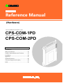
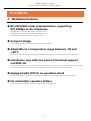
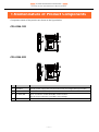
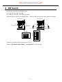
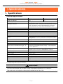
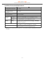
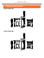
Contec CPS-COM-2PD is an extension COM port that performs RS-422A/485-compliant serial communication with an external device and operates along with the configurable type controller of CONPROSYS series. It has 2 channels of RS-422A/485 communication port, each supporting baud rates from 15 to 921,600bps. The compact design (25.2 (W)×94.7(D)×124.8 (H)) and easy installation with two pieces of terminal support and DIN rail make it suitable for various environments and applications. It also features an LED for operation check, allowing visual confirmation of the communication status.
Contec CPS-COM-2PD is an extension COM port that performs RS-422A/485-compliant serial communication with an external device and operates along with the configurable type controller of CONPROSYS series. It has 2 channels of RS-422A/485 communication port, each supporting baud rates from 15 to 921,600bps. The compact design (25.2 (W)×94.7(D)×124.8 (H)) and easy installation with two pieces of terminal support and DIN rail make it suitable for various environments and applications. It also features an LED for operation check, allowing visual confirmation of the communication status.


-
 1
1
-
 2
2
-
 3
3
-
 4
4
-
 5
5
-
 6
6
-
 7
7
-
 8
8
-
 9
9
-
 10
10
-
 11
11
-
 12
12
-
 13
13
-
 14
14
-
 15
15
-
 16
16
-
 17
17
-
 18
18
-
 19
19
-
 20
20
-
 21
21
-
 22
22
-
 23
23
-
 24
24
-
 25
25
-
 26
26
-
 27
27
-
 28
28
-
 29
29
-
 30
30
-
 31
31
-
 32
32
-
 33
33
-
 34
34
-
 35
35
-
 36
36
-
 37
37
-
 38
38
-
 39
39
-
 40
40
-
 41
41
-
 42
42
-
 43
43
-
 44
44
-
 45
45
-
 46
46
-
 47
47
-
 48
48
-
 49
49
-
 50
50
-
 51
51
-
 52
52


Contec CPS-COM-2PD Reference guide
- Type
- Reference guide
- This manual is also suitable for
Contec CPS-COM-2PD is an extension COM port that performs RS-422A/485-compliant serial communication with an external device and operates along with the configurable type controller of CONPROSYS series. It has 2 channels of RS-422A/485 communication port, each supporting baud rates from 15 to 921,600bps. The compact design (25.2 (W)×94.7(D)×124.8 (H)) and easy installation with two pieces of terminal support and DIN rail make it suitable for various environments and applications. It also features an LED for operation check, allowing visual confirmation of the communication status.
Ask a question and I''ll find the answer in the document
Finding information in a document is now easier with AI
Related papers
-
Contec CPSN-DI-16BCL Owner's manual
-
Contec CPSN-DO-08BL Owner's manual
-
-
-
Contec CPS-SSI-4P Owner's manual
-
-
-
-
-
Other documents
-
Macally HRTABLETORG Owner's manual
-
Shelly Dimmer 2 User guide
-
Digitus DK-113029 Datasheet
-
M-system Current Loop Supply M3LDY Operating instructions
-
 Telenetics DSP 9612 User manual
-
ICP DAS USA I-7514U User manual
-
Mitsubishi Electric MTConnect Data Collector User manual
-
Omega OMB-SER-488A Owner's manual
-
Hatco GRHD, GRCD Series Owner's manual
-
Omron NT631 User manual
