
1
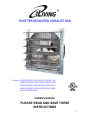
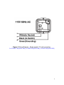
SHUTTER MOUNTED EXHAUST FAN
Models: ILG8SF10V(APB-10A)/ILG8SF12V(APB-12A)
ILG8SF16V(APB-16A)/ILG8SF18V(APB-18A)
ILG8SF18S(APB-18B)/ILG8SF20V(APB-20A)
ILG8SF24V(APB-24A)/ILG8SF30S(APB-30B)
ILG8SF36S(APB-36B)
OWNER'S MANUAL
PLEASE READ AND SAVE THESE
INSTRUCTIONS

PLEASE READ AND SAVE THESE INSTRUCTIONS. READ CAREFULLY BEFORE
ATTEMPTING TO ASSEMBLE, INSTALL, OPERATE
DESCRIBED.
PROTECT YOURSELF AND OTHERS BY OBSERVING ALL SAFETY
INFORMATION. FAILURE TO COMPLY WITH INSTRUCTIONS COULD RESULT IN
PERSONAL INJURY AND/OR PROPERTY DAMAGE! RETAIN INSTRUCTIONS FOR
FUTURE REFERENCE.
BEFORE YOU BEGIN
WARNING!
of parts
are to be performed only by
Electrical Requirements:
• The motor amperage and voltage ratings must be
compatibility to supply voltage prior to final
refer t
o the motor's nameplate label.
Wiring
must conform to local
Tools / Materials Needed:
• Mounting Fasteners (8)
• Sealant or Caulk
• Regular Screwdriver Set
Recommended Accessories:
• Speed control for
ILG8SF10V(
ILG8SF16V(APB-16A),
ILG8SF18V(
ILG8SF24V(APB-24A)
UNPACKING
Contents:
• Shutter Mounted
Exhaust Fan
• Owner’s Manual
Inspect:
• After unpacking
fan, carefully inspect
occurred during transit. Check for loose, missing, or damaged parts.
• Check all bolts, screws, set
occurred during transit.
Tighten as needed
ensure it turns freely.
• See
General Safety Instructions
as shown.
PLEASE READ AND SAVE THESE INSTRUCTIONS. READ CAREFULLY BEFORE
ATTEMPTING TO ASSEMBLE, INSTALL, OPERATE
, OR MAINTAIN THE
PROTECT YOURSELF AND OTHERS BY OBSERVING ALL SAFETY
INFORMATION. FAILURE TO COMPLY WITH INSTRUCTIONS COULD RESULT IN
PERSONAL INJURY AND/OR PROPERTY DAMAGE! RETAIN INSTRUCTIONS FOR
Installation, troubleshooting, and
replacement
are to be performed only by
authorized service technicians
• The motor amperage and voltage ratings must be
checked for
compatibility to supply voltage prior to final
electrical connection. Please
o the motor's nameplate label.
must conform to local
, state, and national codes.
Tools / Materials Needed:
Recommended Accessories:
ILG8SF10V(
APB-10A), ILG8SF12V(APB-
12A
ILG8SF18V(
APB-18A), ILG8SF20V(
APB
Exhaust Fan
fan, carefully inspect
for any damage that may have
occurred during transit. Check for loose, missing, or damaged parts.
• Check all bolts, screws, set
-
screws, etc. for looseness that may have
Tighten as needed
. Rotate propeller by hand to
General Safety Instructions
on page 3, and
Cautions and Warnings
2
PLEASE READ AND SAVE THESE INSTRUCTIONS. READ CAREFULLY BEFORE
PRODUCT
PROTECT YOURSELF AND OTHERS BY OBSERVING ALL SAFETY
INFORMATION. FAILURE TO COMPLY WITH INSTRUCTIONS COULD RESULT IN
PERSONAL INJURY AND/OR PROPERTY DAMAGE! RETAIN INSTRUCTIONS FOR
replacement
authorized service technicians
.
checked for
electrical connection. Please
12A
),
APB
-20A),
for any damage that may have
occurred during transit. Check for loose, missing, or damaged parts.
screws, etc. for looseness that may have
. Rotate propeller by hand to
Cautions and Warnings

3
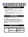
Fans are UL/cUL Listed, Standard 705.
1. Do not depend on any switch as the sole means of disconnecting
power when installing or servicing the fan.
2. Always disconnect, lock-out, and tag-out power source before installing
or servicing. Failure to disconnect power source can result in fire, shock,
or serious injury.
3. Motor will restart without warning after thermal protector trips. Do not
touch operating motor; it may be hot enough to cause injury.
4. Do not place body parts or objects in fan or motor openings while motor
is connected to the power source.
5. All electrical connections should be made by a qualified electrician.
6. These utility exhaust fans are for general purpose exhaust applications
only. Do not use these exhaust fans in an area where corrosive or
explosive materials may be found.
7. Follow all local and state/provincial electrical and safety codes in the
United States and Canada, as well as the National Electrical Code (NEC)
and the Occupational Safety and Health Act (OSHA) in the United States,
and the Canadian Electric Code (CEC) in Canada.
8. Always disconnect power source before working on or near a motor or its
connected load.
9. Protect the power cable from coming in contact with sharp objects.
10. Do not kink or create tight bends in the power cable and never allow the
cable to come in contact with oil, grease, hot surfaces, or chemicals.
11. Make certain that the power source conforms to the requirements of
your specific exhaust fan model. The fan frame and motor must be
electrically grounded to a suitable electrical ground, such as a grounded
water pipe or ground wire system.
12. To reduce the risk of injury to persons, please observe the following:
In the United States, OSHA compliant guards are required when fan is
installed within 7 feet of the floor or working level. In Canada, CSA
compliant guards are required when fan is installed below 2.5 meters
(8.2 feet) above the floor or grade level.
13. Questions? Please contact our service center by calling 1-800-317-
1688.
GENERAL SAFETY INSTRUCTIONS

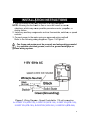
INSTALLATION INSTRUCTION
1. The unit should be securely mounted in a rigid
NOTE:
Allowing the fan frame to flex or move will result in
vibrations, which may cause
shutter failure.
2. Install any auxiliary components such as thermostats, switches, or speed
controls.
3. Conn
ect power to the motor
Refer to the following wiring diagrams
Fan frame and motor must be securely and adequately grounded
to a suitable electrical ground, such as a ground water pipe or
ground wiring system.
Figure 1
:
Wiring Diagram
for ILG8SF10V(APB-10A)
,
ILG8SF18V(APB-18A),
ILG8SF20V(
INSTALL
ATION
INSTALLATION INSTRUCTION
1. The unit should be securely mounted in a rigid
framework.
Allowing the fan frame to flex or move will result in
excess
vibrations, which may cause
possible premature motor, propeller, or
2. Install any auxiliary components such as thermostats, switches, or speed
ect power to the motor
using an approved wiring method.
Refer to the following wiring diagrams
: Figure 1 & Figure 2.
Fan frame and motor must be securely and adequately grounded
to a suitable electrical ground, such as a ground water pipe or
Wiring Diagram
- Speed Controllable. 115-volt
connection.
,
ILG8SF12V(APB-12A),
ILG8SF16V(
ILG8SF20V(
APB-20A
), ILG8SF24V(A
ATION
INSTRUCTIONS
4
excess
possible premature motor, propeller, or
2. Install any auxiliary components such as thermostats, switches, or speed
using an approved wiring method.
Fan frame and motor must be securely and adequately grounded
to a suitable electrical ground, such as a ground water pipe or
connection.
ILG8SF16V(
APB-16A),
), ILG8SF24V(A
PB-24A)
INSTRUCTIONS

5
Figure 2: Wiring Diagram - Single speed. 115-volt connection.
for ILG8SF18S(APB-18B), ILG8SF30S(APB-30B), ILG8SF36S(APB-36B)

6
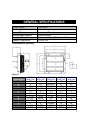
Power source
115V, 60Hz
Mounting Position
Vertical
Frame Material
Galvanized Steel
Shutter Blade Material
Aluminum Alloy
Propeller Material
Aluminum Alloy and Galvanized Steel
Agency Compliance
UL/cUL 705
Dimensions (Inches)
Model
ILG8SF10V
(APB-10A)
ILG8SF12V
(APB-12A)
ILG8SF16V
(APB-16A)
ILG8SF18V
(APB-18A)
ILF8SF18S
(APB-18B)
Prop. Dia
10" 12” 16” 18" 18"
A
13" 15” 18 29/32”
21" 21"
B
13" 15” 18 29/32”
21" 21"
C
4 17/32" 5 3/4” 5 3/4” 5 3/4" 5 3/4"
D
2" 2” 2” 2" 2"
E
5 7/8" 6 5/32” 7 7/8” 8 3/4" 10 13/16"
N
11 21/32"
13 5/8” 17 3/4” 19 11/16"
19 11/16"
G
10 1/8" 12 1/8” 16” 18" 18"
F
10 1/8" 12 1/8” 16” 18" 18"
O
6" 8” 11 29/32” 14" 14"
H
3 17/32” 3 1/2” 3 17/32” 3 17/32” 3 17/32”
J
9/32" 9/32” 9/32” 9/32” 9/32”
GENERAL SPECIFICATIONS
Figure 3

7
I
1/2" 1/2” 1/2” 1/2” 1/2”
Suggested
Wall
Opening(Sq)
10 1/2"
13”
17”
19”
19”
Model ILG8SF20V
(APB-20A)
ILG8SF24V
(APB-24A)
ILG8SF30S
(APB-30B)
ILG8SF36S
(APB-36B)
Prop.Dia
20” 24” 30” 36”
A
23” 27” 33” 39”
B
23” 27” 33” 39”
C
5 3/4” 5 3/4” 5 3/4” 5 3/4”
D
2” 2” 3” 3”
E
11” 11” 13 3/32” 13 11/16”
N
25 21/32” 25 21/32” 31 5/8” 37 21/32”
G
20” 24 1/8” 30 1/8” 36 5/32”
F
20” 24 1/8” 30 1/8” 36 5/32”
O
16” 20 1/32” 26” 32”
H
3 17/32” 3 17/32” 3 17/32” 3 17/32”
J
9/32” 9/32” 9/32” 9/32”
I
1/2” 1/2” 1/2” 1/2”
Suggested
Wall
Opening(Sq)
21”
25”
31”
37”
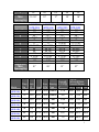
Model
Prop.
Dia
Nom.
HP
Amps
Nom.
RPM
Bearing
Type
Sones@
0.0”SP@
5”
CFM Air
Delivery@Static
Pressure Shown
0.00”
0.125”
0.25”
ILG8SF10V
(APB-10A)
10" 1/25 0.55 1550
Sleeve 6.19 600 354 N/A
ILG8SF12V
(APB-12A)
12” 1/20 0.60 1625
Sleeve 5.9 772 418 N/A
ILG8SF16V
(APB-16A)
16” 1/20 0.85 1550
Ball 6.39 1200
416 180
ILG8SF18V
(APB-18A)
18" 1/15 0.85 1075
Ball 7.4 1736
1108 N/A
ILG8SF18S
(APB-18B)
18" 1/4 3.50 1725
Ball 7.28 3852
2836 2172
ILG8SF20V
(APB-20A)
20" 1/4 2.75 1075
Ball 6.67 3368
2312 1868
ILG8SF24V
(APB-24A)
24” 1/4 2.75 1075
Ball 7.0 4244
2676 2220

ILG8SF30S
(APB-30B)
30” 1/3
3.30
ILG8SF36S
(APB-36B)
36” 1/2
6.00
1. Keep the area free of
objects that could impede air flow on both the
intake and exhaust side of fan.
2. For proper exhaust operation, a window, door, or louver should be
opened for fresh air intake on the opposite
ventilated.
3. Turn the fan ON;
the shutt
turned OFF, the shutter will close.
4. Speed controllable units are designed to operate at a minimum of fifty
percent line voltage.
1. Disconnect power source before servicing.
2. Periodically clean
off accumulated dirt from
and shutter.
Do not depend on any switch as
disconn
ecting power when installing or
disconnect is not visible
,
Failure to do so may result in fatal electrical shock.
Employ proper lock
maintenance.
Symptom
Possible Cause(s)
Dry motor bearings
Loose propeller
OPERATING INSTRUCTIONS
TROUBLESHOOTING
MAINTAINANCE
3.30
825 Ball 7.01 5088
6.00
825 Ball 8.24 6128
objects that could impede air flow on both the
intake and exhaust side of fan.
2. For proper exhaust operation, a window, door, or louver should be
opened for fresh air intake on the opposite
side of the area to be
the shutt
er will open automatically. When the unit is
turned OFF, the shutter will close.
4. Speed controllable units are designed to operate at a minimum of fifty
1. Disconnect power source before servicing.
off accumulated dirt from
the propeller, guard, motor,
Do not depend on any switch as
the sole means of
ecting power when installing or
servicing. If power
,
utilize OSHA Lock out/Tag out procedure.
Failure to do so may result in fatal electrical shock.
Employ proper lock
-out/tag-
out procedures when performing
Possible Cause(s)
Solution
Dry motor bearings
Re-
lubricate motor
bearings as per
instructions
or replace motor.
Loose propeller
Tighten set screws on
propeller hub.
OPERATING INSTRUCTIONS
TROUBLESHOOTING
MAINTAINANCE
8
3432 1552
4380 2620
objects that could impede air flow on both the
2. For proper exhaust operation, a window, door, or louver should be
side of the area to be
er will open automatically. When the unit is
4. Speed controllable units are designed to operate at a minimum of fifty
the propeller, guard, motor,
servicing. If power
utilize OSHA Lock out/Tag out procedure.
out procedures when performing
Solution
lubricate motor
instructions
or replace motor.
Tighten set screws on

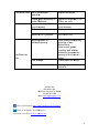
Excessive noise
Bent or damaged
propeller
Loose guard assembly or
motor fasteners.
Fan inoperative
Blown fuse
circuit breaker
Defective motor
Switch in
Insufficient air
flow
Blocked intake or
exhaust opening
Low voltage
Speed control set too low
South San Francisco, CA
Email:
Like us on Facebook:
https://www.facebook.com/ilivingusa/
Follow us on Twitter: @iLIVINGUSA
Check out our website:
www.ilivingusa.com
Bent or damaged
propeller
Replace propeller
Loose guard assembly or
motor fasteners.
Tighten as required to 15
20 lbs. per inch.
Blown fuse
or open
circuit breaker
Replace fuse or reset
circuit breaker
Defective motor
Replace motor
Switch in
OFF position Turn switch ON
Blocked intake or
exhaust opening
Clear intake and exhaust
openings of any
obstructions.
Clean
motor, guard,
propeller, and
shutter
assembly.
Increase the
opening of the fresh air
intake.
Low voltage
Check electrical wiring.
Speed control set too low
Increase speed with
controller
iLIVING USA
239 Harbor Way
South San Francisco, CA
94080
Tel: 800-317-1688
Email:
servic[email protected]
https://www.facebook.com/ilivingusa/
Follow us on Twitter: @iLIVINGUSA
www.ilivingusa.com
9
Replace propeller
Tighten as required to 15
-
Replace fuse or reset
Clear intake and exhaust
motor, guard,
shutter
Increase the
opening of the fresh air
Check electrical wiring.
Increase speed with

10
-
 1
1
-
 2
2
-
 3
3
-
 4
4
-
 5
5
-
 6
6
-
 7
7
-
 8
8
-
 9
9
-
 10
10


iLIVING ILG8SF36S User manual
- Type
- User manual
- This manual is also suitable for
Ask a question and I''ll find the answer in the document
Finding information in a document is now easier with AI
Related papers
-
iLIVING ILG8SF10V Operating instructions
-
iLIVING ILG8SF20V-T User manual
-
-
iLIVING ILG8SF12V-ST User manual
-
-
-
-
-
-
Other documents
-
Cumberland Funnel Flow Stir Fans Owner's manual
-
Hessaire 36SF-H Operating instructions
-
 Strongway Enclosed Single-Speed Shutter Exhaust Fan Owner's manual
-
Johnson Controls LN-PFCUA-1 Installation Instructions Manual
-
COBHAM GR716-BOARD Quick start guide
-
CAME RBM21 Owner's manual
-
-
-
Microchip Technology Microsemi Hello FPGA Libero Design User manual
-
Raymarine RS232 Owner's Handbook Manual
