Page is loading ...

8 byTrademark Global LLC
Trademark Global
LLC.

Page 2
Table of Contents
Safety ......................................................... 2
Specifications ............................................. 3
Operation .................................................... 4
Operation .................................................... 5
Maintenance ............................................... 7
WARNING SYMBOLS AND DEFINITIONS
This is the safety alert symbol. It is used to alert you to potential personal injury hazards.
Obey all safety messages that follow this symbol to avoid possible injury or death.
Indicates a hazardous situation which, if not avoided,
will result in death or serious injury.
Indicates a hazardous situation which, if not avoided,
could result in death or serious injury.
Indicates a hazardous situation which, if not avoided,
could result in minor or moderate injury.
Addresses practices not related to personal injury.
IMPORTANT SAFETY INSTRUCTIONS
INSTRUCTIONS PERTAINING TO A
RISK OF FIRE, ELECTRIC SHOCK,
OR INJURY TO PERSONS
WARNING – When using tools, basic precautions
should always be followed, including the following:
1. Wear ANSI-approved safety goggles during
set up and use of the Battery Tester.
2. Test in a well ventilated area.
Explosive gases may be produced during testing.
Do not smoke, cause sparks, or strike
matches near the battery when testing.
3. Refer to the user manual of the Battery being
tested for testing instructions and precautions
prior to using the Battery Tester.
4. Do not connect in reverse polarity.
5. Do not expose this product to rain or wet conditions.
6. Maintain this product. Check for breakage
of parts and any other condition that may
affect this product’s operation. If damaged,
have the unit repaired before use.
7. Use this product in accordance with these
instructions, taking into account the working
conditions and the work to be performed.
Use of this product for operations different from those
intended could result in a hazardous situation.
8. This product is not a toy.
Keep it out of reach of children.
9. Maintain labels and nameplates on the unit.
These carry important safety information.
10. People with pacemakers should consult their
physician(s) before use. Electromagnetic fields in
close proximity to heart pacemaker could cause
pacemaker interference or pacemaker failure.
Caution is necessary when near coil, spark
plug cables, or distributor of running engine. Engine
should be off during distributor adjustment.
11. Undercharged lead-acid batteries
will freeze during cold weather.
Do not test or charge a froz en battery.
SAFETY OPERATION MAINTENANCESPECIFICATIONS

Page 3
12. When connecting the Battery Cables to the
battery, avoid creating sparks; especially when
the battery is being charged. Explosive gases
are created during charging. Sparking could
also damage the vehicle electrical system.
13. Do not touch the cooling vents on the Battery
Tester during or immediately after testing
the battery. They become very hot.
14. When placing the Battery Tester in the vehicle’s
engine compartment, take special care that
the metal housing of the Tester does not
come in contact with either terminal of the
battery or other electrical connections.
15. Be certain of the test battery polarity before
connecting the test Cable Clamps. The red Cable
Clamp goes to the positive terminal of the battery.
The black Cable Clamp goes to the negative terminal
of the battery. Reversing Battery Tester Cable
Clamps on the battery will damage the tester.
16. Do not drop the Battery Tester as it
may affect proper operation.
17. Do not smoke or have open flames near the battery.
18. Do not connect the Battery Tester to
the battery while the engine is running.
Turn the engine off before connecting.
19. The warnings and precautions discussed in this
manual cannot cover all possible conditions and
situations that may occur. It must be understood
by the operator that common sense and caution
are factors which cannot be built into this
product, but must be supplied by the operator.
SAVE THESE INSTRUCTIONS.
Specifications
Testing
Capability
6 and 12 VDC battery tester
Load Test
Capacity
100 amps;
500 ~ 1000 cold cranking amps
Display Meters Analog, 0 ~ 16 VDC (max.)
Test Cycle
10 seconds per test with
1 minute cool down;
3 tests in 5 minutes
Battery Cable 16-3/4 IN. long including clamps
Clamps Copper plated clamps
SAFETYOPERATIONMAINTENANCE SPECIFICATIONS

Page 4
Operating Instructions
Read the ENTIRE IMPORTANT SAFETY INFORMATION section at the beginning of this
manual including all text under subheadings therein before set up or use of this product.
Testing the Battery
1. To help ensure a good connection, wipe the battery
terminals with a cloth to remove any dirt and grease.
2. Connect the red (positive) Cable Clamp
to the positive terminal (+) on the 6 or
12V lead-acid battery.
3. Connect the black (negative) Cable Clamp to the
negative terminal ( –) on the battery. Turn clamps
slightly to ensure a good connection.
4. With the clamps connected, the tester’s gauge will
show the battery’s current charge.
If it is less than 12V, disconnect the
battery and recharge before testing.
If the recharging will not bring the reading above
12V, the battery is defective. If it shows no reading,
verify that the tester is connected properly. If the
tester is connected properly, the battery is defective.
5. Press (and hold) the Switch for
at least 5 seconds to simulate an actual load
on the battery.
6. View the Meter Display and read
the battery condition. Refer to the
“Battery Condition Analysis” chart on page 5.
7. Release the Switch and remove
the Cable Clamps from the battery.
Testing the Charging System
AVOID CARBON MONOXIDE POISONING. This gas comes from the vehicle’s exhaust and
is colorless and odorless. It can cause SERIOUS INJURY or DEATH if inhaled.
1. Connect the Cable Clamps to the
battery as previously described.
2. Outside, or in a well ventilated area, start the
vehicle engine and run at fast idle speed.
3. View the Meter Display and read the charging
system condition (far right on the gauge). Refer to
the “Battery Condition Analysis” section to the right.
4. Turn vehicle’s engine off, then remove Cable Clamps.
Testing the Starter
NOTE: The engine should be at normal
operating temperature and the battery should
be fully charged before doing this test.
1. Connect the Cable Clamps to the
battery as previously described.
2. Disable the ignition so the engine will not start.
(Refer to your vehicle’s manual.)
3. Have an assistant crank the engine.
Note the voltage reading during cranking.
4. View the Meter Display and read the voltage.
A reading of 9 Volts or less indicates
excessive current draw. This may be
due to a poor connection, a failing starter,
or a battery of insufficient size for the motor.
5. When finished, disconnect the Cable Clamps,
restore ignition and store tool in a clear,
dry location away from children.
SAFETY OPERATION MAINTENANCESPECIFICATIONS

Page 5
Battery Condition Analysis
Meter Display
Load Test / 15 Seconds
(Display Reading)
Battery Condition
OK
(Green Area)
Battery capacity is good. May or may not be fully
charged. Check the charge state by testing the Specific
Gravity (SG) with a Hydrometer (not included).
If SG is less than full charge, check for possible
charging system trouble. Recharge to full level.
Weak
(Yellow Area)
If the Display Meter needle is steady, the battery capacity is not
good. Battery may be defective or partly discharged. Check SG.
If over 1.225, the battery is defective.
If below 1.225, recharge battery and retest.
If there is a difference in SG between cells over 2 points
(0.025), a particular cell may be damaged.
If charging does not bring SG to full charge level, then
battery is either sulfated or has lost its active material.
Bad
(Red Area)
If the Display Meter needle is falling, the battery is defective
or has a bad cell. For a quick check, release the load
Toggle Switch and note Display Meter reaction.
If voltage recovers to its full potential after only a few
seconds, the battery is probably defective.
If the voltage recovers slowly, the battery may only
be run down. Check SG, recharge and retest.
Charging System
(Alt. & Reg Test)
If the Display Meter needle reads OK, charging system is functional.
If it falls on the low red or high red areas, charging
system may be malfunctioning.
SAFETYOPERATIONMAINTENANCE SPECIFICATIONS

Page 6
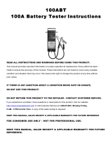
Functions
Black Negative
Cable Clamp
Red Positive
Cable Clamp
Handle
Switch
Meter Display
SAFETY OPERATION MAINTENANCESPECIFICATIONS

Page 7
User-Maintenance Instructions
Procedures not specifically explained in this manual must
be performed only by a qualified technician.
TO PREVENT SERIOUS INJURY FROM ACCIDENTAL OPERATION:
Do not use damaged equipment. If abnormal noise or vibration,
occurs, have the problem corrected before further use.
Inspection, Maintenance, and Cleaning
Note: These procedures are in addition to the regular checks and maintenance
explained as part of the regular operation of the air-operated tool.
1. Periodically check all nuts, bolts, and screws for tightness.
2. Store in a clean, dry location.
3. Clean the outside of the unit with a damp cloth. Never use solvents to clean
any parts of this tool. Allow tool to dry completely before use.
4. Use compressed air to blow out debris from the load vents.
5. After each use, clean the Cable Clamps of any possible battery electrolyte.
Apply a thin coat of silicon grease to prevent corrosion.
SAFETYOPERATIONMAINTENANCE SPECIFICATIONS
/