Page is loading ...

Publication 1794-IN049D-EN-P - January 2009
Installation Instructions
FLEX I/O 2 Input Frequency Module
Cat. No. 1794-IJ2, 1794-IJ2K, and 1794-IJ2XT
(Modules with a K in the last position of the catalog number are
conformally coated to meet noxious gas requirements of ISA/ANSI-71.040
1985 Class G3 Environment.)
European Hazardous Location Approval
The following frequency input modules are European Zone 2 approved:
1794-IJ2, 1794-IJ2K, and 1794-IJ2XT
Important User Information
Solid state equipment has operational characteristics differing from those of electromechanical
equipment. Safety Guidelines for the Application, Installation and Maintenance of Solid State
Controls (Publication SGI-1.1
available from your local Rockwell Automation sales office or
online at http://literature.rockwellautomation.com
) describes some important differences
between solid state equipment and hard-wired electromechanical devices. Because of this
difference, and also because of the wide variety of uses for solid state equipment, all persons
responsible for applying this equipment must satisfy themselves that each intended application
of this equipment is acceptable.
In no event will Rockwell Automation, Inc. be responsible or liable for indirect or consequential
damages resulting from the use or application of this equipment.
The examples and diagrams in this manual are included solely for illustrative purposes. Because
of the many variables and requirements associated with any particular installation, Rockwell
Automation, Inc. cannot assume responsibility or liability for actual use based on the examples
and diagrams.
No patent liability is assumed by Rockwell Automation, Inc. with respect to use of information,
circuits, equipment, or software described in this manual.
Reproduction of the contents of this manual, in whole or in part, without written permission of
Rockwell Automation, Inc. is prohibited.
Throughout this manual we use notes to make you aware of safety considerations.
WARNING
Identifies information about practices or circumstances that can cause an
explosion in a hazardous environment, which may lead to personal injury
or death, property damage, or economic loss.
IMPORTANT
Identifies information that is critical for successful application and
understanding of the product.
ATTENTION
Identifies information about practices or circumstances that can lead to
personal injury or death, property damage, or economic loss. Attentions
help you:
• identify a hazard
• avoid a hazard
• recognize the consequence
ATTENTION
Environment and Enclosure
This equipment is intended for use in a Pollution Degree 2 industrial
environment, in overvoltage Category II applications (as defined in IEC
publication 60664-1), at altitudes up to 2000 meters (6562 ft) without
derating.
This equipment is considered Group 1, Class A industrial equipment according
to IEC/CISPR Publication 11. Without appropriate precautions, there may be
potential difficulties ensuring electromagnetic compatibility in other
environments due to conducted as well as radiated disturbance.
This equipment is supplied as open-type equipment. It must be mounted
within an enclosure that is suitably designed for those specific environmental
conditions that will be present and appropriately designed to prevent
personal injury resulting from accessibility to live parts. The enclosure must
have suitable flame-retardant properties to prevent or minimize the spread of
flame, complying with a flame spread rating of 5VA, V2, V1, V0 (or equivalent)
if non-metallic. The interior of the enclosure must be accessible only by the
use of a tool. Subsequent sections of this publication may contain additional
information regarding specific enclosure type ratings that are required to
comply with certain product safety certifications.
In addition to this publication, see:
• Industrial Automation Wiring and Grounding Guidelines, for additional
installation requirements, Allen-Bradley publication 1770-4.1
.
• NEMA Standards publication 250 and IEC publication 60529, as
applicable, for explanations of the degrees of protection provided by
different types of enclosure.
WARNING
If you insert or remove the module while backplane power is on, an
electrical arc can occur. This could cause an explosion in hazardous location
installations.
Be sure that power is removed or the area is nonhazardous before
proceeding.
WARNING
If you connect or disconnect wiring while the field-side power is on, an
electrical arc can occur. This could cause an explosion in hazardous location
installations. Be sure that power is removed or the area is nonhazardous
before proceeding.
ATTENTION
Personnel responsible for the application of safety-related Programmable
Electronic Systems (PES) shall be aware of the safety requirements in the
application of the system and shall be trained in using the system.
ATTENTION
Do not remove or replace a Terminal Base unit while power is applied.
Interruption of the backplane can result in unintentional operation or machine
motion.
ATTENTION
FLEX I/O is grounded through the DIN rail to chassis ground. Use zinc plated
yellow-chromate steel DIN rail to assure proper grounding. The use of other
DIN rail materials (for example, aluminum or plastic) that can corrode, oxidize,
or are poor conductors, can result in improper or intermittent grounding.
Secure DIN rail to mounting surface approximately every 200 mm (7.8 in.) and
use end-anchors appropriately.
ATTENTION
Preventing Electrostatic Discharge
This equipment is sensitive to electrostatic discharge, which can cause
internal damage and affect normal operation. Follow these guidelines when
you handle this equipment:
• Touch a grounded object to discharge potential static.
• Wear an approved grounding wriststrap.
• Do not touch connectors or pins on component boards.
• Do not touch circuit components inside the equipment.
• Use a static-safe workstation, if available.
• Store the equipment in appropriate static-safe packaging when not in
use.
ATTENTION
To reduce susceptibility to noise, power analog modules and digital modules
from separate power supplies. Do not exceed a total length of 9.8 ft (3m) for
dc power cabling.
European Zone 2 Certification (The following applies when the product bears the Ex
or EEx Marking)
This equipment is intended for use in potentially explosive atmospheres as defined by European
Union Directive 94/9/EC and has been found to comply with the Essential Health and Safety
Requirements relating to the design and construction of Category 3 equipment intended for use
in potentially explosive atmospheres, given in Annex II to this Directive.
Compliance with the Essential Health and Safety Requirements has been assured by compliance
with EN 60079-15 and EN 60079-0.

2
Publication 1794-IN049D-EN-P - January 2009
North American Hazardous Location Approval
The following frequency input modules are North American Hazardous
Location approved: 1794-IJ2, 1794-IJ2K, and 1794-IJ2XT.
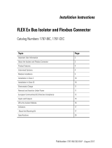
Installing Your Frequency Input Module
The module mounts on a 1794-TB3G or -TB3GS terminal base.
1. Rotate the keyswitch (1) on the terminal base (2) clockwise to
position 1 as required for this type of module.
2. Make certain the flexbus connector (3) is pushed all the way to the
left to connect with the neighboring termbase/adapter. You
cannot install the module unless the connector is fully
extended.
3. Make sure the pins on the bottom of the module are straight so
they will align properly with the connector in the terminal base.
4. Position the module (4) with its alignment bar (5) aligned with the
groove (6) on the terminal base.
5. Press firmly and evenly to seat the module in the terminal base
unit. The module is seated when the latching mechanism (7) is
locked into the module.
Connecting Wiring for the 1794-TB3G, and -TB3GS
Connect wiring as shown here.
Wiring Connections for the Frequency Input Module using the 1794-TB3G
or -TB3GS Terminal Base Unit
WARNING
Observe the following additional Zone 2 certification requirements.
• This equipment is not resistant to sunlight or other sources of UV
radiation.
• This equipment must be installed in an enclosure providing at least IP54
protection when applied in Zone 2 environments.
• This equipment shall be used within its specified ratings defined by
Allen-Bradley.
• Provision shall be made to prevent the rated voltage from being
exceeded by transient disturbances of more than 40% when applied in
Zone 2 environments.
• Secure any external connections that mate to this equipment by using
screws, sliding latches, threaded connectors, or other means provided
with this product.
• Do not disconnect equipment unless power has been removed or the
area is known to be nonhazardous.
ATTENTION
To comply with the CE Low Voltage Directive (LVD), all connections to this
equipment must be powered from a source compliant with the following:
Safety Extra Low Voltage (SELV) or Protected Extra Low Voltage (PELV).
The following information applies when operating this
equipment in hazardous locations:
Informations sur l’utilisation de cet équipement en
environnements dangereux :
Products marked “CL I, DIV 2, GP A, B, C, D” are suitable for
use in Class I Division 2 Groups A, B, C, D, Hazardous
Locations and nonhazardous locations only. Each product is
supplied with markings on the rating nameplate indicating the
hazardous location temperature code. When combining
products within a system, the most adverse temperature code
(lowest “T” number) may be used to help determine the
overall temperature code of the system. Combinations of
equipment in your system are subject to investigation by the
local Authority Having Jurisdiction at the time of installation.
Les produits marqués "CL I, DIV 2, GP A, B, C, D" ne conviennent
qu’à une utilisation en environnements de Classe I Division 2
Groupes A, B, C, D dangereux et non dangereux. Chaque produit
est livré avec des marquages sur sa plaque d’identification qui
indiquent le code de température pour les environnements
dangereux. Lorsque plusieurs produits sont combinés dans un
système, le code de température le plus défavorable (code de
température le plus faible) peut être utilisé pour déterminer le
code de température global du système. Les combinaisons
d’équipements dans le système sont sujettes à inspection par
les autorités locales qualifiées au moment de l’installation.
WARNING
EXPLOSION HAZARD
• Do not disconnect equipment
unless power has been removed or
the area is known to be
nonhazardous.
• Do not disconnect connections to
this equipment unless power has
been removed or the area is known
to be nonhazardous. Secure any
external connections that mate to
this equipment by using screws,
sliding latches, threaded
connectors, or other means
provided with this product.
• Substitution of components may
impair suitability for Class I,
Division 2.
• If this product contains batteries,
they must only be changed in an
area known to be nonhazardous.
AVERTISSEMENT
RISQUE D’EXPLOSION
• Couper le courant ou s’assurer
que l’environnement est classé
non dangereux avant de
débrancher l'équipement.
• Couper le courant ou s'assurer
que l’environnement est classé
non dangereux avant de
débrancher les connecteurs. Fixer
tous les connecteurs externes
reliés à cet équipement à l'aide
de vis, loquets coulissants,
connecteurs filetés ou autres
moyens fournis avec ce produit.
• La substitution de composants
peut rendre cet équipement
inadapté à une utilisation en
environnement de Classe I,
Division 2.
• S’assurer que l’environnement
est classé non dangereux avant
de changer les piles.
ATTENTION
During mounting of all devices, be sure that all debris (metal chips, wire
strands, etc.) is kept from falling into the module. Debris that falls into the
module could cause damage on power up.
1
2
3
4
5
6
7
WARNING
If you remove or insert the module while the backplane power is on, an
electrical arc can occur. This could cause an explosion in hazardous location
installations. Be sure that power is removed or the area is nonhazardous
before proceeding.
ATTENTION
To reduce susceptibility to noise, power analog modules and digital modules
from separate power supplies. Do not exceed a length of 3 m (9.8 ft) for DC
power cabling.
ATTENTION
Do not daisy chain power or ground from this terminal base unit to any AC or
DC digital module terminal base units.
Output Alarm
Connections
Channel 0 Terminals
1
Channel 1 Terminals
1
Sply + Sply
RET
Out + Out
RET
Sply + Sply
RET
Out + Out
RET
Supply C-37 C-39 C-46 C-48
Output B-17 B-18 B-31 B-32
1 Connect cable shields to GND connections.
17 18 19 20 21 22 23 24 25 26 27 28 29 30 31 32 33
0 1 2 3 4 5 6 7 8 9 10 11 12 13 14 15
16
35 36 37 38 39 40 41 42 43 44 45 46 47 48 49 50 51
34
Wiring Connections for the 1794-TB3G and -TB3GS
Chassis
Ground
(1794-TB3G shown)
Chassis
Ground
+V COM
24V dc
Supply In
+V COM
24V dc
Supply Out
Chassis Grounds for Shields
Chassis
Ground
Chassis
Ground
+24V dc = Terminals C-34 and C-50
COM = C-35 and C-51
Chassis Ground = Terminals B-16, B-33, C-38, C-40 thru 45, and C-47
A
B
C
For daisy-chaining: Supply in - C-34 (+) and C-35 (-)
Supply out - C-50 (+) and C-51 (-)
3V 6V 24V
PWR
RET 50
mV
SEL
500/50
mV
SEL
F 24V
PWR
24V
PWR
24V
PWR
3V6VRET50
mV
SEL
500/50
mV
SEL
F
RET 50
mV
SEL
500/50
mV
SEL
G 24V
PWR
24V
PWR
RET50
mV
SEL
500/50
mV
SEL
GOUT 0 OUT 0
RET
OUT 1 OUT 1
RET
Channel 0 Frequency Input
Channel 0 Gate Input
Channel 1 Frequency Input
Channel 1 Gate Input
Sply0 Sply0
RET
Sply1 Sply1
RET
Channel 0 Output Supply
Channel 1 Output Supply
NC
NC
NC = No connection
NC NC

3
Publication 1794-IN049D-EN-P - January 2009
Resolution and Accuracy
+1Hz or +0.1Hz (depending on frequency range bit setting), or + accuracy
specification listed below, whichever is greater.
Input Map
Output Map
Types of Inputs
Channel 0 Terminals
5
Channel 1 Terminals
5
Power Input
RET
6
Power Input
RET
6
GND
5
Frequency
24V DC IEC 1+ Proximity
1,2
A-7 A-6 A-3 A-8 A-9 A-12
24V DC Contact Switch
3
A-7 A-6 A-3 A-8 A-9 A-12
500 mV AC Magnetic Pickup A-7 A-5 A-3 A-8 A-10 A-12
50 mV AC Magnetic Pickup
4
A-7 A-5 A-3 A-8 A-10 A-12
6V AC Vortex A-2 A-1 A-3 A-13 A-14 A-12
3V AC Vortex A-2 A-0 A-3 A-13 A-15 A-12
Gate
24V DC IEC 1+ Proximity
1,2
B-24 B-23 B-20 B-25 B-26 B-29
24V DC Contact Switch
3
B-24 B-23 B-20 B-25 B-26 B-29
500 mV DC Magnetic Pickup B-24 B-22 B-20 B-25 B-27 B-29
50 mV DC Magnetic Pickup
4
B-24 B-22 B-20 B-25 B-27 B-29
1 As defined by standard IEC 1131-2.
2 RET not used on 2-wire devices.
3 Add external resistor from 24V to F (A-6) or G (A-9) for wire-off detection (0.4 mA).
4 Add jumper between 50 mV and RET (frequency - channel 0 = A-4 to A-3; channel 1 = A-11 to
A-12)
(gate - channel 0 = B-21 to B-20; channel 1 = B-28 to B-29).
5 Connect cable shields to GND terminals.
6 All 4 RET terminals (ch0 and 1, Freq. and Gate) are internally connected together.
Accuracy
Min. Freq.
Sample
Time (ms)
Sampling
Accuracy
Time
Base
Accuracy
Worst
Case Total
Accuracy
Deviation in Hz Due
to Total Accuracy
Resolution
1.0-3276.7
Freq.
Range
(in Hz)
1-32767
Freq.
Range
(in Hz)
2+0.02% +0.0225% +0.0425 +0.1-1.4 +1-14 0.01%
4+0.01% +0.0225% +0.0325 +0.1-1.1 +1-11 0.005%
5+0.008% +0.0225% +0.0305 +0.1-1.0 +1-10 0.004%
10 +0.004% +0.0225% +0.0265 +0.1-0.9 +1-9 0.002%
20 +
0.002% +0.0225% +0.0245 +0.1-0.8 +1-8 0.001%
50 +0.0008% +0.0225% +0.0233 +0.1-0.8 +1-8 0.0004%
100 +0.0004% +0.0225% +0.0229 +0.1-0.8 +1-8 0.0002%
200 +0.0002% +0.0225% +0.0227 +0.1-0.7 +1-7 0.0001%
500 +0.00008% +0.0225% +0.02258 +0.1-0.7 +1-7 0.00004%
1000 +0.00004% +0.0225% +0.02254 +0.1-0.7 +1-7 0.00002%
2
minimum frequency sample time
% Resolution =
count frequency X minimum frequency sample time
Accuracy % is defined as:
Resolution % is defined as:
% Accuracy =
count frequency
1
100
minimum frequency
sample time
2
100 1 -
+
Bit
⇒
15 14 13 12 11 10 09 08 07 06 05 04 03 02 01 00
Wor
d⇓
Read
0 Frequency 0…32,767 or 0.0…3,276.7 Channel 0
1
% Full Scale 0.0…3,276.7% Channel 0 or Acceleration -32,768…32,767 Channel 0
2
Frequency 0…32,767 or 0.0…3,276.7 Channel 1
3
% Full Scale 0.0…3,276.7% Channel 1 or Acceleration -32,768…32,767 Channel 1
4 R R Direction
Ch 0
GS
Ch 0
F/A
Ch 0
WO
Ch 0
MPA
Ch 0
R R Directio
n Ch 1
GS
Ch 1
F/A
Ch 1
WO
Ch 1
MPA
Ch 1
5 Reserved Diagnostic Status
Channel 0
Reserved Diagnostic Status
Channel 1
6 Reserved
Where:
GS = Gate state
F/A = Frequency/Accel alarm
WO = Wire-off alarm
MPA = Missing pulse alarm
R = Reserved
Dec
.
15 14 13 12 11 10 9 8 7 6 5 4 3 2 1 0
Oct. 17 16 15 14 13 12 11 10 7 6 5 4 3 2 1 0
0 CF SSM FR
Ch
0
Number of
pulses to
terminate
sampling 0-7
Ch 0
MPM 0-3
Ch 0
RLFFR
Ch
1
Number of
pulses to
terminate
sampling 0-7 Ch
1
MPM
0-3
Ch 1
1 Maximum Frequency 0 - 32.767 or 0.0 - 3,276.7 - or -
Absolute Value of Acceleration - 0 to 32767 Channel 0
2 Frequency Scaling Divisor 0-255 Channel 0 Frequency Scaling Multiplier 0-255
Channel 0
3WOF
G Ch
0
WOF
F Ch
0
IGI
Ch
0
IFI
Ch
0
Minimum Frequency
Sample Time 0-15
Ch 0
Init
St
Up
Ch 0
ACT
0-3
Ch 0
F/AA
S Ch
0
MPDM
0-3 Ch 0
WOFM
0-3 Ch
0
4 Maximum Frequency 0 - 32,767 or 0.0 - 3,276.7 - or -
Absolute Value of Acceleration - 0 to 32,767 Channel 1
5 Frequency Scaling Divisor 0-255 Channel 1 Frequency Scaling Multiplier 0-255
Channel 1
6WOF
G Ch
1
WOF
F Ch
1
IGI
Ch
1
IFI
Ch
1
Minimum Frequency
Sample Time 0-15
Ch 1
Init
St
Up
Ch 1
ACT
0-3
Ch 1
F/AA
S Ch
1
MPDM
0-3 Ch 1
WOFM
0-3 Ch
1
7 Reserved
Where:CF = Communication Fault
SSM = Safe state mode
FR = Frequency range
MPM = Missing pulse multiplier
LF = Local Fault mode
F/AAS = Frequency/Accel alarm select
WOFF = Wire-off fault frequency
WOFG = Wire-off fault gate
WOFM = Wire-off fault mode
IGI = Invert gate input
IFI = Invert frequency input
ACT = Acceleration calculation time
MPDM = Missing pulse delay multiplier
R = Reserved

4
Publication 1794-IN049D-EN-P - January 2009
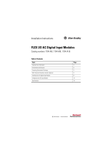
Status Indicators
When an input indicator (yellow) is lighted, it indicates that a valid signal
(active high or active low) is present at one of the Input terminals.
When wire-off detection is enabled, and a wire-off fault is detected (24 V
DC IEC 1+ input terminal only), a fault indicator (red) is blinked/flashed at
a rate of 1Hz to signal a fault condition. A wire-off fault signal will also be
sent to the backplane. A flashing red fault indication means a valid wire-off
condition for a 24 V DC IEC 1+ Input or a 24 V DC contact switch input
with a shunt resistor.
When an output indicator is yellow, the logic is driving an output alarm
On. After detecting a fault, the internal circuitry will set the output data to
the appropriate safe state, as defined by the module data table. Safe state
control may be adapter dependent. The input and output indicators are on
the field side of the isolation path, and display the logic state of the actual
microcontroller input and output.
The status indicator initially powers up as solid green, indicating the power
supply is operating and internal diagnostic tests are being performed. After
a successful power up test, the indicator remains green. The indicator turns
red in about 1.5 s if there is an internal diagnostics error. The module is
operating correctly when the green OK indicator is on.
A red OK indicator shows that the module is in a Faulted condition
(internal error).
Diagnostics
The frequency input module returns diagnostics to the PLC processor in
word 5 of the BTR file. These diagnostics give you information on the
status or condition of the module.
BTR Word 5
Indicator Condition Operating Description
Input (0, 1)
(Freq, or Gate)
Off (Dark) Input Turned Off, Input Not Used, or Wire Disconnected
On (Yellow) Input Turned On (Active High or Active Low if Inverted)
Fault (F)
(Freq, or Gate)
Off (Dark) Wire Connected, Normal Operation or Detection Disabled
On (Red
Flashing)
Wire Disconnected, Fault Condition (for IEC 1+ Proximity switch
or switch contacts with shunt resistor)
Output Alarm
(0, 1)
Off (Dark) Output Alarm Turned Off
On (Yellow) Output Alarm Turned On (Logic Drive On)
Status (OK) Off (Dark) 24V Power Turned Off, or 5V Logic Power Problem
Solid Green Module OK, Normal Operating Mode
Solid Red Module Fault, Outputs Disabled
FREQ GATE
OK
0
FREQUENCY
INPUT 2 CHANNEL
1
1794-IJ2
A
ll
e
n
-
B
r
a
d
l
ey
E
B
F0F
FREQ GATE
1F 1F
OUT
0
OUT
1
C DA
A
=
Input indicator.
B
=
Insertable label for writing individual I/O assignments.
C
=
Wire-Off Fault indicator.
D
=
Output indicator.
E
=
Power/status indicator - indicates power applied to module and status of module.
1794-IJ2 shown
15 14 13 12 11 10 09 08 07 06 05 04 03 02 01 00
word 5
See Table for diagnostics
44760
Input
Word
Bit Definition
Word 5 Bits
00 - 03
Diagnostic Status - indciates the response from the module; a normal or
non-normal operating condition.
Bit 03020100
00000 = Normal Operation (No Failure)
00011 = Calibration Failure
00102 = Configuration Failure
A Minimum Frequency Sample Time value other
than 0-9 was selected.
00113 = Message Failure
01004 = Lead Break Detection Hardware Failure
01015 = Major Hardware Failure
01106 = EEPROM Failure
01117 = RAM Failure
10008 = ROM Failure
10019 = Calculation Failure
The actual Frequency is greater than 32,767 Hz or
3,276.7 Hz (overange). The scaled Frequency is
greater than 32,767 Hz or 3,276.7 Hz (overange).
The % Full Scale calculation (based on Maximum
Frequency) is > 3,276.7%.
1010 - 1111 10 - 15 = Not used
Specifications - Frequency Input Module, Cat. Nos. 1794-IJ2, 1794-IJ2K, and
1794-IJ2XT
Input Specifications
Number of input
channels
2
Number of inputs per
channel
2 - Frequency and Gate (gate used to establish direction)
Input frequency Maximum - 1-32 kHz w/sine wave; 1-32 kHz w/square wave input
Frequency value Maximum 32,767 or 3,276.7 (dependent on range)
Input pulse width 20 μs
Resolution/Accuracy Refer to Resolution/Accuracy table
On-stage voltage, min 10V (24V IEC+1 proximity, encoder input or switch inputs)
On-state voltage, nom
(selected by terminal
base connections)
50 mV AC, 28V AC peak - Extended Magnetic Pickup
500 mV AC, 28V AC peak - Magnetic Pickup
< 3V - Vortex Flowmeter low range
> 6V - Vortex Flowmeter high range
24V DC IEC+1 proximity or encoder input
24V DC Contact Switch input
On-state voltage, max Limited to isolated 24V DC power supply maximum
On-state current
minimum
nominal
maximum
2.0 mA
9.0 mA
10.0 mA
Off-state current, min 1.5 mA into 24V DC IEC+ terminal
Off-state voltage, max 5.0V DC on 24V DC IEC+1 terminal
Wire-off detection 0.4 mA for proximity, encoder or contact switch with 50 kΩ shunt resistor
Frequency input
impedance
>5 KΩ for 50 mV Extended Magnetic Pickup
>5 KΩ for 500 mV Magnetic Pickup
>10 KΩ for 3V Vortex Flowmeter low range
>10 KΩ for 6V Vortex Flowmeter high range
>2.5 KΩ for 24V DC IEC+1 proximity or encoder input
>2.5 KΩ for 24V DC Contact Switch input
Gate input impedance >5 KΩ for 50 mV Extended Magnetic Pickup
>5 KΩ for 500 mV Magnetic Pickup
>2.5 KΩ for 24V DC IEC+1 proximity or encoder input
>2.5 KΩ for 24V DC Contact Switch input
Output Specifications (meets IEC 1A 24V DC output specifications)
Number of outputs 2 isolated
Output voltage source Customer supplied
Output voltage
minimum
nominal
maximum
10V DC
24V DC
31.2V DC
Off-state voltage, max 31.2V DC
On-state current 1 mA per output minimum
1.0 A per channel sourced out of module maximum
Current Limited - All outputs can be on simultaneously without derating
Surge current 2 A for 50 ms, repeatable every 2 s
Off-state leakage Less than 300 μA at 31.2V DC maximum

5
Publication 1794-IN049D-EN-P - January 2009
On-state voltage drop 0.9V DC at 1 A
Output control Outputs individually assignable to: Frequency, % Full Scale or Acceleration
Alarm
Output switching time Triggered by frequency alarm or acceleration alarm
Turn on: Less than 0.5 ms
Turn off: Less than 1 ms
General
Module location Cat. No. 1794-TB3G and -TB3GS Terminal Base Units
External DC power
Voltage range
Supply voltage
Supply current
(Input for +5V logic and 24V DC/DC converters)
19.2…31.2V DC (includes 5% AC ripple)
24V DC nominal
220 mA @ 19.2V DC; 180 mA @ 24V DC; 140 mA @ 31.2V DC
Isolated DC power
Voltage range
Supply voltage
Supply current
Peak AC ripple
(Output to sensors and encoders)
21.6…26.4V DC
24V DC nominal
0-60 mA maximum @ 24V DC (4 devices @ 15 mA = 60 mA)
100 mV maximum
Dimensions (with
module installed in
base)
94H x 94W x 69D mm (3.7H x 3.7W x 2.7D in.)
Isolation voltage 50V (continuous), Basic Insulation Type
Type tested at 1365V AC for 60 s, between field side and system and
individual channels
Processing time <4 ms
Flexbus current 30 mA at 5V DC
Power dissipation 4.6W maximum at 31.2V DC
Thermal dissipation Maximum 15.6 BTU/hr at 31.2V DC
Indicators (field side
driven, logic side
indication)
1 green/red power/status indicator
4 yellow status indicators (Freq 0, 1, Gate 0, 1)
4 red wire-off indicators (Freq 0, 1, Gate 0, 1)
2 yellow status indicators (Out 0, Out 1) - logic side
Keyswitch Position 1
Wire size Determined by installed terminal base
Wiring category
1
2 - on signal ports
3 - on power ports
Wire type Shielded on signal ports
Terminal screw torque Determined by installed terminal base
Enclosure type rating None (open-style)
North American temp
code
T4A
IEC temp code T4
Environmental
Operating temperature IEC 60068-2-1 (Test Ad, Operating Cold),
IEC 60068-2-2 (Test Bd, Operating Dry Heat),
IEC 60068-2-14 (Test Nb, Operating Thermal Shock):
0…55 °C (32…131 °F) (1794-IJ2 and 1794-IJ2K)
-20…70 °C (-4…158 °F) (1794-IJ2XT)
Non-operating
temperature
IEC 60068-2-1 (Test Ab, Unpackaged Non-operating Cold),
IEC 60068-2-2 (Test Bb, Unpackaged Non-operating Dry Heat),
IEC 60068-2-14 (Test Na, Unpackaged Non-operating Thermal Shock):
-40…85 °C (-40…185 °F)
Relative humidity IEC 60068-2-30 (Test Db, Unpackaged Damp Heat):
5…95% noncondensing
Vibration IEC 60068-2-6 (Test Fc, Operating):
5 g @ 10…500 Hz
Operating shock IEC 60068-2-27 (Test Ea, Unpackaged Shock):
30 g
Non-operating shock IEC 60068-2-27 (Test Ea, Unpackaged Shock):
50 g
Emissions CISPR 11:
Group 1, Class A (with appropriate enclosure)
ESD immunity IEC 61000-4-2:
4 kV contact discharges (1794-IJ2 and 1794-IJ2K)
6 kV contact discharges (1794-IJ2XT)
8 kV air discharges
Radiated RF immunity IEC 61000-4-3:
10V/m with 1 kHz sine-wave 80% AM from 80…2000 MHz
10V/m with 200 Hz 50% Pulse 100% AM at 900 MHz
10V/m with 200 Hz 50% Pulse 100% AM at 1890 MHz
3V/m with 1 kHz sine-wave 80% AM from 2000…2700 MHz
EFT/B immunity IEC 61000-4-4:
±2 kV at 5 kHz on power ports
±2 kV at 5 kHz on shielded signal ports
Surge transient
immunity
IEC 61000-4-5:
±2 kV line-earth(CM) on shielded signal ports
Conducted RF
immunity
IEC 61000-4-6:
10V rms with 1 kHz sine-wave 80% AM from 150 kHz…80 MHz on shielded
signal ports
Certifications
Certifications
(when product is
marked)
2
Value
c-UL-us UL Listed Industrial Control Equipment, certified for US and Canada. See UL
File E65584.
UL Listed for Class I, Division 2 Group A,B,C,D Hazardous Locations, certified
for U.S. and Canada. See UL File E194810.
CSA
(1794-IJ2 and
1794-IJ2K)
CSA Certified Process Control Equipment. See CSA File LR54689C.
CSA Certified Process Control Equipment for Class I, Division 2 Group A,B,C,D
Hazardous Locations. See CSA File LR69960C.
CE European Union 2004/108/EC EMC Directive, compliant with:
EN 61326-1; Meas./Control/Lab., Industrial Requirements
EN 61000-6-2; Industrial Immunity
EN 61000-6-4; Industrial Emissions
EN 61131-2; Programmable Controllers (Clause 8, Zone A & B)
C-Tick Australian Radiocommunications Act, compliant with:
AS/NZS CISPR 11; Industrial Emissions
Ex European Union 94/9/EC ATEX Directive, compliant with:
EN 60079-15; Potentially Explosive Atmospheres, Protection "n" (II 3 G Ex nA
IIC T4 X)
EN 60079-0; General Requirements (Zone 2)
TÜV TÜV Certified for Functional Safety:
up to and including SIL 2
1 Use this Conductor Category information for planning conductor routing. Refer to Industrial
Automation Wiring and Grounding Guidelines, publication
1770-4.1.
2 See the Product Certification link at http://www.ab.com for Declaration of Conformity, Certificates,
and other certification details.

Publication 1794-IN049D-EN-P - January 2009 6 PN-38821
Supersedes Publication 1794-IN049C-EN-P - June 2004 Copyright © 2009 Rockwell Automation, Inc. All rights reserved.
/