Page is loading ...

MODEL T31637/T31638
ROUTER LIFT w/TABLE INSERT
OWNER'S MANUAL
(For models manufactured since 01/20)
COPYRIGHT © FEBRUARY, 2020 BY GRIZZLY INDUSTRIAL, INC.
WARNING: NO PORTION OF THIS MANUAL MAY BE REPRODUCED IN ANY SHAPE
OR FORM WITHOUT THE WRITTEN APPROVAL OF GRIZZLY INDUSTRIAL, INC.
#MN20970 PRINTED IN TAIWAN
V1.02.20

This manual provides critical safety instructions on the proper setup,
operation, maintenance, and service of this machine/tool. Save this
document, refer to it often, and use it to instruct other operators.
Failure to read, understand and follow the instructions in this manual
may result in fire or serious personal injury—including amputation,
electrocution, or death.
The owner of this machine/tool is solely responsible for its safe use.
This responsibility includes but is not limited to proper installation in
a safe environment, personnel training and usage authorization,
proper inspection and maintenance, manual availability and compre-
hension, application of safety devices, cutting/sanding/grinding tool
integrity, and the usage of personal protective equipment.
The manufacturer will not be held liable for injury or property damage
from negligence, improper training, machine modifications or misuse.
Some dust created by power sanding, sawing, grinding, drilling, and
other construction activities contains chemicals known to the State
of California to cause cancer, birth defects or other reproductive
harm. Some examples of these chemicals are:
• Lead from lead-based paints.
• Crystalline silica from bricks, cement and other masonry products.
• Arsenic and chromium from chemically-treated lumber.
Your risk from these exposures varies, depending on how often you
do this type of work. To reduce your exposure to these chemicals:
Work in a well ventilated area, and work with approved safety equip-
ment, such as those dust masks that are specially designed to filter
out microscopic particles.

Table of Contents
INTRODUCTION ............................................................................................................................... 2
Contact Info
................................................................................................................................ 2
Manual Accuracy
........................................................................................................................ 2
Identification
............................................................................................................................... 3
Controls & Components
............................................................................................................. 4
T31637 Machine Data Sheet
..................................................................................................... 5
T31638 Machine Data Sheet
..................................................................................................... 6
SECTION 1: SAFETY
....................................................................................................................... 7
Safety Instructions for Machinery
............................................................................................... 7
Additional Safety for Router Tables
........................................................................................... 9
SECTION 2: SETUP
....................................................................................................................... 10
Unpacking
................................................................................................................................ 10
Needed for Setup
..................................................................................................................... 10
Inventory
................................................................................................................................... 10
Installing Router
....................................................................................................................... 11
Installing Router Lift Assembly
................................................................................................. 12
Installing Crank Handle Bracket
............................................................................................... 13
SECTION 3: OPERATIONS
........................................................................................................... 14
Operation Overview.................................................................................................................. 14
Stock Inspection Requirements
............................................................................................... 15
Table T-Slots
............................................................................................................................ 16
Squaring Fence & Table T-Slot
................................................................................................ 16
Adjusting Router Height
........................................................................................................... 17
Using Table Insert
.................................................................................................................... 17
Edge Jointing............................................................................................................................ 18
Profile Routing
.......................................................................................................................... 19
Routing Small Stock
................................................................................................................. 19
Free-Hand Routing
................................................................................................................... 20
SECTION 4: ACCESSORIES
......................................................................................................... 22
SECTION 5: MAINTENANCE......................................................................................................... 24
Schedule
.................................................................................................................................. 24
Cleaning & Protecting
.............................................................................................................. 24
SECTION 6: SERVICE
................................................................................................................... 25
Troubleshooting
........................................................................................................................ 25
Aligning Mounting Plate
........................................................................................................... 26
SECTION 7: PARTS
....................................................................................................................... 27
Main
.......................................................................................................................................... 27
WARRANTY & RETURNS
............................................................................................................. 29

-2-
Model T31637/T31638 (Mfd. Since 01/20)
We stand behind our machines! If you have ques-
tions or need help, contact us with the information
below. Before contacting, make sure you get the
serial number
and manufacture date
from the
machine ID label. This will help us help you faster.
Grizzly Technical Support
1815 W. Battlefield
Springfield, MO 65807
Phone: (570) 546-9663
Email: [email protected]
We want your feedback on this manual. What did
you like about it? Where could it be improved?
Please take a few minutes to give us feedback.
Grizzly Documentation Manager
P.O. Box 2069
Bellingham, WA 98227-2069
Email: [email protected]
Contact Info
We are proud to provide a high-quality owner’s
manual with your new machine!
We
made every effort to be exact with the
instruc-
tions, specifications, drawings, and photographs
in this manual. Sometimes we make mistakes, but
our policy of continuous improvement also means
that
sometimes the machine
you receive is
slightly different than shown in the manual
.
If you find this to be the case, and the difference
between the manual and machine leaves you
confused or unsure about something
,
check our
website for an updated version. W
e post
current
manuals and
manual updates for free
on our web-
site at
www.grizzly.com.
Alternatively, you can call our Technical Support
for help. Before calling, make sure you write down
the
Manufacture Date and Serial Number
from
the machine ID label (see below). This information
is required for us to provide proper tech support,
and it helps us determine if updated documenta-
tion is available for your machine.
Manufacture Date
Serial Number
Manual Accuracy
INTRODUCTION

Model T31637/T31638 (Mfd. Since 01/20)
-3-
Identification
Become familiar with the names and locations of the controls and features shown below to better understand
the instructions in this manual.
For Your Own Safety Read Instruction Manual Before Operating Router Table
a) Wear eye protection.
b) Always keep router bit guard in place and in proper operating condition.
c
) Feed workpiece AGAINST rotation of router bit.
d
) Keep fingers away from revolving bit–use fixtures when necessary.
e
) Do not use awkward hand positions.
Crank
Handle
Carriage
Table
Insert
Index
Ring
Clamp
Plates
Mounting
Plate

-4-
Model T31637/T31638 (Mfd. Since 01/20)
Controls &
Components
To reduce your risk of
serious injury, read this
entire manual BEFORE
using machine.
Refer to the following figures and descriptions to
become familiar with the basic controls and com-
ponents of this machine. Understanding these
items and how they work will help you understand
the rest of the manual and minimize your risk of
injury when operating this machine.
A. Mounting Plate. Attaches router to table.
B. Table Insert. Provides additional workpiece
control and safety near bit during operations.
C. Carriage Lock. Secures carriage position to
prevent movement during operations.
D. Index Ring. Insert crank handle and rotate to
move carriage up and down.
E. Crank Handle. Inserts into index ring to raise
and lower carriage.
F. Router Clamp Plates. Secure router to
carriage.
G. Carriage. Moves up and down the guides as
leadscrew is turned with crank handle.
Figure 1. Mounting plate components.
D
A
B
C
Figure 2. Lift components.
E
F
G

Model T31637/T31638 (Mfd. Since 01/20)
-5-
T31637 Machine Data Sheet
Page 1 of 1 Model T31637
MODEL T31637
ROUTER LIFT WITH 12" X 9" TABLE INSERT
Customer Service #: (570) 546-9663 · To Order Call: (800) 523-4777 · Fax #: (800) 438-5901
Product Dimensions:
Weight ............................................................................................................................................................................. 13 lbs.
Width (side-to-side) x Depth (front-to-back) x Height .....................................................................................12 x 9 x 7-1/2 in.
Shipping Dimensions:
Type ................................................................................................................................................................... Cardboard Box
Content .......................................................................................................................................................................... Machine
Weight .............................................................................................................................................................................. 14 lbs.
Length x Width x Height .....................................................................................................................................15 x 13 x 11 in.
Must Ship Upright .................................................................................................................................................................Yes
Main Specifications:
Suitable Routers for Mounting .................................................................................................................3.200", 3.500", 4.200"
Plate Size ............................................................................................................................................................ 12 x 9
x 3/8 in.
Plate Opening Size ........................................................................................................................................................ 3-3/4
in.
Table Insert Size ............................................................................................................................................................ 3-3/4
in.
Table Insert Opening Size ............................................................................................................................................. 1-1/4
in.
Router Lift Travel ........................................................................................................................................................... 2-3/4
in.
Router Lift Index Ring Increment .................................................................................................................0.05 in. per full turn
Construction:
Router Lift ........................................................................................................................................................ Aluminum, Steel
Plate ............................................................................................................................................................Anodized Aluminum
Table Insert .........................................................................................................................................................Polycarbonate
Other Specifications:
Country of Origin ............................................................................................................................................................. Taiwan
Warranty ........................................................................................................................................................................... 1 Year
ISO 9001 Factory ..................................................................................................................................................................Yes
Features:
Precision-Machined Router Lift
Inch/Millimeter Settings
Index Ring for Fine Lift Adjustment of Router
Accessories:
Table Insert w/1-1/4" Diameter Bit Hole
Table Insert Wrench
Starting Pin
Hex Wrench 3mm

-6-
Model T31637/T31638 (Mfd. Since 01/20)
T31638 Machine Data Sheet
Page 1 of 1 Model T31638
MODEL T31638
ROUTER LIFT WITH 11-3/4" X 9-1/4" TABLE INSERT
Customer Service #: (570) 546-9663 · To Order Call: (800) 523-4777 · Fax #: (800) 438-5901
Product Dimensions:
Weight ............................................................................................................................................................................. 13 lbs.
Width (side-to-side) x Depth (front-to-back) x Height ........................................................................ 11-3/4 x 9-1/4 x 7-1/2 in.
Shipping Dimensions:
Type ................................................................................................................................................................... Cardboard Box
Content .......................................................................................................................................................................... Machine
Weight .............................................................................................................................................................................. 14 lbs.
Length x Width x Height .....................................................................................................................................15 x 13 x 11 in.
Must Ship Upright .................................................................................................................................................................Yes
Main Specifications:
Suitable Routers for Mounting .................................................................................................................3.200", 3.500", 4.200"
Plate Size ............................................................................................................................................... 11-3/4 x 9-1/4 x 3/8 in.
Plate Opening Size ........................................................................................................................................................ 3-3/4
in.
Table Insert Size ............................................................................................................................................................ 3-3/4
in.
Table Insert Opening Size ............................................................................................................................................. 1-1/4
in.
Router Lift Travel ........................................................................................................................................................... 2-3/4
in.
Router Lift Index Ring Increment .................................................................................................................0.05 in. per full turn
Construction:
Router Lift ........................................................................................................................................................ Aluminum, Steel
Plate ............................................................................................................................................................Anodized Aluminum
Table Insert .........................................................................................................................................................Polycarbonate
Other Specifications:
Country of Origin ............................................................................................................................................................. Taiwan
Warranty ........................................................................................................................................................................... 1 Year
ISO 9001 Factory ..................................................................................................................................................................Yes
Features:
Precision-Machined Router Lift
Inch/Millimeter Settings
Index Ring for Fine Lift Adjustment of Router
Accessories:
Table Insert w/1-1/4" Diameter Bit Hole
Table Insert Wrench
Starting Pin
Hex Wrench 3mm

Model T31637/T31638 (Mfd. Since 01/20)
-7-
ELECTRICAL EQUIPMENT INJURY RISKS.
You can be shocked, burned, or killed by touching
live electrical components or improperly grounded
machinery. To reduce this risk, only allow qualified
service personnel to do electrical installation or
repair work, and always disconnect power before
accessing or exposing electrical equipment.
DISCONNECT POWER FIRST.
Always discon-
nect machine from power supply BEFORE mak-
ing adjustments, changing tooling, or servicing
machine. This prevents an injury risk from unin-
tended startup or contact with live electrical com-
ponents.
EYE PROTECTION. Always wear ANSI-approved
safety glasses or a face shield when operating or
observing machinery to reduce the risk of eye
injury or blindness from flying particles. Everyday
eyeglasses are NOT approved safety glasses.
OWNER’S MANUAL. Read and understand this
owner’s manual BEFORE using machine.
TRAINED OPERATORS ONLY. Untrained oper-
ators have a higher risk of being hurt or killed.
Only allow trained/supervised people to use this
machine. When machine is not being used, dis-
connect power, remove switch keys, or lock-out
machine to prevent unauthorized use—especially
around children. Make your workshop kid proof!
DANGEROUS ENVIRONMENTS. Do not use
machinery in areas that are wet, cluttered, or have
poor lighting. Operating machinery in these areas
greatly increases the risk of accidents and injury.
MENTAL ALERTNESS REQUIRED. Full mental
alertness is required for safe operation of machin-
ery. Never operate under the influence of drugs or
alcohol, when tired, or when distracted.
For Your Own Safety, Read Instruction
Manual Before Operating This Machine
The purpose of safety symbols is to attract your attention to possible hazardous conditions.
This manual uses a series of symbols and signal words intended to convey the level of impor-
tance of the safety messages. The progression of symbols is described below. Remember that
safety messages by themselves do not eliminate danger and are not a substitute for proper
accident prevention measures. Always use common sense and good judgment.
Indicates a potentially hazardous situation which, if not avoided,
MAY result in minor or moderate injury. It may also be used to alert
against unsafe practices.
Indicates a potentially hazardous situation which, if not avoided,
COULD result in death or serious injury.
Indicates an imminently hazardous situation which, if not avoided,
WILL result in death or serious injury.
Alerts the user to useful information about proper operation of the
machine to avoid machine damage.
NOTICE
Safety Instructions for Machinery
SECTION 1: SAFETY

-8-
Model T31637/T31638 (Mfd. Since 01/20)
WEARING PROPER APPAREL. Do not wear
clothing, apparel or jewelry that can become
entangled in moving parts. Always tie back or
cover long hair. Wear non-slip footwear to reduce
risk of slipping and losing control or accidentally
contacting cutting tool or moving parts.
HAZARDOUS DUST. Dust created by machinery
operations may cause cancer, birth defects, or
long-term respiratory damage. Be aware of dust
hazards associated with each workpiece mate-
rial. Always wear a NIOSH-approved respirator to
reduce your risk.
HEARING PROTECTION. Always wear hear-
ing protection when operating or observing loud
machinery. Extended exposure to this noise
without hearing protection can cause permanent
hearing loss.
REMOVE ADJUSTING TOOLS. Tools left on
machinery can become dangerous projectiles
upon startup. Never leave chuck keys, wrenches,
or any other tools on machine. Always verify
removal before starting!
USE CORRECT TOOL FOR THE JOB. Only use
this tool for its intended purpose—do not force
it or an attachment to do a job for which it was
not designed. Never make unapproved modifica-
tions—modifying tool or using it differently than
intended may result in malfunction or mechanical
failure that can lead to personal injury or death!
AWKWARD POSITIONS. Keep proper footing
and balance at all times when operating machine.
Do not overreach! Avoid awkward hand positions
that make workpiece control difficult or increase
the risk of accidental injury.
CHILDREN & BYSTANDERS. Keep children and
bystanders at a safe distance from the work area.
Stop using machine if they become a distraction.
GUARDS & COVERS. Guards and covers reduce
accidental contact with moving parts or flying
debris. Make sure they are properly installed,
undamaged, and working correctly BEFORE
operating machine.
FORCING MACHINERY. Do not force machine.
It will do the job safer and better at the rate for
which it was designed.
NEVER STAND ON MACHINE. Serious injury
may occur if machine is tipped or if the cutting
tool is unintentionally contacted.
STABLE MACHINE. Unexpected movement dur-
ing operation greatly increases risk of injury or
loss of control. Before starting, verify machine is
stable and mobile base (if used) is locked.
USE RECOMMENDED ACCESSORIES. Consult
this owner’s manual or the manufacturer for rec-
ommended accessories. Using improper acces-
sories will increase the risk of serious injury.
UNATTENDED OPERATION. To reduce the
risk of accidental injury, turn machine OFF and
ensure all moving parts completely stop before
walking away. Never leave machine running
while unattended.
MAINTAIN WITH CARE. Follow all maintenance
instructions and lubrication schedules to keep
machine in good working condition. A machine
that is improperly maintained could malfunction,
leading to serious personal injury or death.
DAMAGED PARTS. Regularly inspect machine
for damaged, loose, or mis-adjusted parts—or
any condition that could affect safe operation.
Immediately repair/replace BEFORE operating
machine. For your own safety, DO NOT operate
machine with damaged parts!
MAINTAIN POWER CORDS. When disconnect-
ing cord-connected machines from power, grab
and pull the plug—NOT the cord. Pulling the cord
may damage the wires inside. Do not handle
cord/plug with wet hands. Avoid cord damage by
keeping it away from heated surfaces, high traffic
areas, harsh chemicals, and wet/damp locations.
EXPERIENCING DIFFICULTIES. If at any time
you experience difficulties performing the intend-
ed operation, stop using the machine! Contact our
Technical Support at (570) 546-9663.

Model T31637/T31638 (Mfd. Since 01/20)
-9-
Serious cuts, amputation, entanglement, or death can occur from contact with spinning bit.
Improperly secured bits or spindle parts/fasteners can fly off and strike nearby operators
or bystanders with great force. Flying dust or debris from cutting operation can cause eye
injuries or blindness. To minimize risk of getting hurt or killed, anyone operating router MUST
completely heed hazards and warnings below.
CUTTING SUPPORT. NEVER cut workpiece
without using a fence, jig, or miter gauge as a
support guide. Otherwise, workpiece could be
aggressively pulled from your hands, drawing
them into spinning bit.
WORKPIECE SIZING. NEVER use workpiece
shorter than 6" without special fixtures or jigs.
Otherwise, workpiece can become trapped
between fence and router bit, which could draw
your hands into spinning bit.
USING SAFETY GUARDS. To prevent ampu-
tation or other injuries, always use a guard.
Fabricate additional guards or jigs for special
circumstances. Use an overhead guard if fence
is removed.
TRIPPING HAZARD. To prevent tripping over
power cord of router when not in use, always dis-
connect it and safely store it out of way.
APPROPRIATE WORKPIECES. Danger of kick-
back and injury is increased when workpiece
has knots, holes, or foreign objects in it. Warped
stock should be flattened with a jointer before you
shape it with router.
TESTING ROTATION. With router disconnected
from power, rotate router spindle to test any new
setup to ensure proper bit clearance before start-
ing router.
INSTALLING ROUTER BIT. Insert at least
3
⁄4 of
bit shank into collet, and allow
1
⁄8" of clearance
between shank and bottom of collet to ensure bit
is securely installed.
AVOIDING AMPUTATION. To avoid making con-
tact with spinning router bit, never place hands
directly over or in front of bit. As one hand
approaches bit, move it away and over to other
side. Always keep hands at least 6" away from
spinning bit.
SECURING LEVERS AND KNOBS. Never oper-
ate router table without first making sure all lock
levers and knobs are tight, and all fence hardware
and guide rails are secure. Otherwise, workpiece
can slip out of alignment while cutting and cause
injury from kickback.
DO NOT FORCE WORKPIECE. Never force
materials past router. Let router bit do the work.
Excessive force is likely to result in poor cutting
results and will cause kickback conditions that
could cause serious personal injury.
BLIND CUTTING. Keep router bit on underside
of workpiece when making blind cuts. This will
decrease risk of accidental contact with spinning
bit.
ROUTER BIT ROTATION. Always feed work-
piece against rotation direction of bit. Otherwise,
workpiece could be aggressively pulled from your
hands, drawing them into spinning bit.
ROUTER BIT HEIGHT. Keep any unused portion
of bit below the table surface to minimize risk of
your hand contacting spinning bit.
ROUTER BIT SPEED. Do not exceed recom-
mended speed of any router bit. Doing so can
cause bit to fracture or explode and cause injury.
Additional Safety for Router Tables

-10-
Model T31637/T31638 (Mfd. Since 01/20)
SECTION 2: SETUP
This machine was carefully packaged for safe
transport. When unpacking, separate all enclosed
items from packaging materials and inspect them
for shipping damage.
If items are damaged
,
please
call us immediately
at (570) 546-9663.
IMPORTANT:
Save all packaging materials until
you are completely satisfied with the machine and
have resolved any issues between Grizzly or the
shipping agent. You MUST have the original pack-
aging to file a freight claim. It is also extremely
helpful if you need to return your machine later.
Unpacking
Inventory
The following is a list of items shipped with your
machine. Before beginning setup, lay these items
out and inventory them.
If any non-proprietary parts are missing (e.g. a
nut or a washer), we will gladly replace them; or
for the sake of expediency, replacements can be
obtained at your local hardware store.
The following items are needed, but not included,
for the setup/assembly of this machine.
Description Qty
• Straightedge 48" ......................................... 1
• Hex Wrenches 3, 5mm ............................... 1
• 12" 2x4s ...................................................... 2
Needed for Setup
This machine presents
serious injury hazards
to untrained users. Read
through this entire manu-
al to become familiar with
the controls and opera-
tions before starting the
machine!
Wear safety glasses during
the entire setup process!
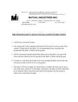
Box 1 Contents (Figure 3) Qty
A. Router Lift Assembly (T31637) ................... 1
Router Lift Assembly (T31638) ................... 1
B. Crank Handle ............................................. 1
C. Table Insert Wrench ................................... 1
D. Flange Bolts
5
⁄16"-18 x
1
⁄2" ........................... 2
E. Crank Handle Storage Bracket................... 1
F. Cap Screws M4-.7 x 16 .............................. 2
G. Starting Pin ................................................. 1
H. Hex Wrench 3mm ....................................... 1
I. Table Insert ................................................. 1
NOTICE
If you cannot find an item on this list, care-
fully check around/inside the machine and
packaging materials. Often, these items get
lost in packaging materials while unpack-
ing or they are pre-installed at the factory.
Figure 3. Inventory.
A
B
C
D
F
E
GHI

Model T31637/T31638 (Mfd. Since 01/20)
-11-
Installing Router
The Model T31637/T31638 router lift is designed
with clamping plates (see Figure 4) that accept
router body diameters of 3.200", 3.500", or 4.200."
Each one of the four clamping plates has two
curved edges—one deep and one shallow.
Through a process of trial and error, determine
which curvature best holds your router in position.
Do not mix and match shallow and deep curves
or the router will not be centered over the hole in
the mounting plate, and you run the risk of hitting
the plate with a bit during operations.
For larger router bodies, remove the clamping
plates completely (see Figure 5) and use the
clamp block and slide block to secure the router
in position.
Figure 4. Location of router clamping plates.
Clamping Plates
Clamping Plates
Figure 5. Clamping plates removed.
Slide Block
Clamp Block
IMPORTANT: When positioning the router in
the clamping plates, take into account access to
router controls, such as variable-speed dial, depth
adjustments, and other locks or levers.
To install router:
1.
Insert crank handle in index ring on mount-
ing plate (see Figure 1 on Page 4) and turn
clockwise until lift just touches the bottom of
the plate.
2. Place lift assembly upside down on two
blocks of wood (see Figure 6) so router collet
will be able to extend through the center hole
in the mounting plate.
3. Loosen (4) cap screws that secure clamp
block to slide block (see Figure 6).
Figure 6. Lift assembly resting on wood blocks.
Slide
Block
Clamp
Block
x 4
Tools Needed: Qty
Hex Wrench 5mm .............................................. 1

-12-
Model T31637/T31638 (Mfd. Since 01/20)
Figure 7. Example of router installed in clamping
plates.
4. Secure router with best configuration of
clamping plates that hold it securely, then
retighten cap screws (see Figure 7).
Note: Router body should just touch the back
of the mounting plate.
5. Install lift assembly in router table (see below).
If router unexpectedly moves or router
bit contacts table insert or fence during
operation, serious personal injury could
result from the router bit or flying debris.
ALWAYS make sure router is firmly secured
in clamping plates before beginning
operations.
Installing Router
Lift Assembly
To ensure a workpiece does not catch on the
mounting plate and cause kickback, the mounting
plate must be aligned evenly with the top of your
router table (not included).
Tools Needed: Qty
Hex Wrench 3mm .............................................. 1
Straightedge 48"
................................................ 1
To install lift assembly:
1.
Position router lift assembly inside table
opening (see Figure 8) so mounting plate is
flush with table top. Then snap table insert
into position.
Straightedge
Mounting
Plate
Table Surface
Figure 9. Pattern for aligning mounting plate.
2.
Lay straightedge across mounting plate, table
insert, and table surfaces in pattern shown in
Figure 9.
3.
Adjust set screws (see Figure 8) in mount-
ing plate so ends of straightedge lay flat
on table surface at all positions of pattern
above.
4.
Once mounting plate is even with table sur-
face, secure position with (2) M4-.7 x 16 cap
screws included with machine (see Figure 8.)
Note: If position of holes in your table does
not match this size and location, it will be nec-
essary to modify your table by drilling and/or
tapping new holes to fit.
Figure 8. Example of router lift assembly
positioned inside table opening.
Cap
Screws
Set Screws
(1 of 8)
Table
Insert

Model T31637/T31638 (Mfd. Since 01/20)
-13-
Installing Crank
Handle Bracket
Figure 10. Example of crank holder installed on
router table leg.
Crank
Holder
x 2
The Model T31637/T31638 comes with a bracket
for storing the crank handle when not in use.
To install crank handle bracket:
1.
Locate position on router table where bracket
is to be installed.
2.
Hold bracket in position and scribe locations
where (2) holes are to be drilled.
3. Drill and tap (2) holes to receive
5
⁄16"-18 x
1
⁄2"
flange bolts that come with machine.
Note: Alternatively, you may also drill (2)
"through holes" and bolt the bracket in place
using your own fasteners.
4. Tighten bolts to secure bracket in place (see
Figure 10).

-14-
Model T31637/T31638 (Mfd. Since 01/20)
SECTION 3: OPERATIONS
To reduce your risk of
serious injury, read this
entire manual BEFORE
using machine.
Eye injuries, respiratory problems, or hear-
ing loss can occur while operating this
tool. Wear personal protective equipment to
reduce your risk from these hazards.
If you are not experienced with this type
of machine, WE STRONGLY RECOMMEND
that you seek additional training outside of
this manual. Read books/magazines or get
formal training before beginning any proj-
ects. Regardless of the content in this sec-
tion, Grizzly Industrial will not be held liable
for accidents caused by lack of training.
Keep hair, clothing, and
jewelry away from mov-
ing parts at all times.
Entanglement can result
in death, amputation, or
severe crushing injuries!
To complete a typical operation, the operator
does the following:
1.
Examines workpiece to make sure it is suit-
able for cutting.
2.
Adjusts fences close to the bit for maximum
workpiece support, then secures fences in
place.
3.
Adjusts bit height for desired cutting
profile.
4. Adjusts fence position to establish depth of
cut and makes sure that it is parallel with the
table T-slot.
5.
Wears safety glasses, respirator, and hearing
protection. Locates push sticks or blocks if
needed.
6.
Starts router.
IMPORTANT: For small or odd-shaped
workpieces, a zero-clearance fence or jig is
used.
7.
Holds workpiece firmly and flatly against table
and fence, then pushes workpiece into bit at
a steady and controlled rate until workpiece
moves completely beyond router bit.
WARNING: Keep workpiece firmly against
table and fence, and keep hands away from
spinning router bit during entire cut.
8.
Stops router once operation is complete.
Operation Overview
No list of safety guidelines can be com-
plete. Every shop environment is different.
Always consider safety first, as it applies
to your individual working conditions. Use
this and other machinery with caution and
respect. Failure to do so could result in
serious personal injury, damage to equip-
ment, or poor work results.

Model T31637/T31638 (Mfd. Since 01/20)
-15-
Stock Inspection
Requirements
End View
Direction of Feed
Outfeed
Fence
Infeed
Fence
Figure 11. Proper grain alignment with the router
bit.
• Only process natural and man-made wood
products. Your router is designed to cut
only natural wood fiber products. It is NOT
designed to cut metal, glass, stone, tile,
products with lead-based paint, or products
that contain asbestos. Cutting these materi-
als with a router may lead to injury.
Always follow these rules when choosing and
routing stock:
•
DO NOT cut
stock that contains large or
loose knots. Injury to the operator or dam-
age to the workpiece can occur if a knot
becomes dislodged during the cutting opera-
tion.
•
DO NOT cut
against the grain direction.
Cutting against the grain increases the like-
lihood of kickback, as well as tearout on the
workpiece.
•
Routing
with the grain produces a better
finish and is safer for the operator.
Cutting
with the grain is described as feeding the
stock on the router table so the grain points
down and toward you as viewed on the edge
of the stock (see Figure below).
Note:
If the grain changes direction along the
edge of the board, decrease the cutting depth
and make additional passes.
• Scrape all glue off the workpiece before
jointing. Glue deposits on the workpiece,
hard or soft, will gum up the router bit, pro-
duce poor results, and increase the risk of
kickback.
• Remove foreign objects from the work-
piece. Make sure that any stock you pro-
cess with the router is clean and free of dirt,
nails, staples, tiny rocks, or any other foreign
objects that could damage the router bit and
be thrown from the machine with significant
speed/force.
Note:
Wood stacked on a concrete or dirt
surface can have small pieces of concrete or
stone pressed into the surface.
• Make sure all stock is sufficiently dried
before routing. Wood with a moisture con-
tent over 20% will cause unnecessary wear
on the router bits, produce poor cutting
results, and increase the risk of kickback.
Excess moisture can also hasten rust and
corrosion.
Like all machinery there is potential danger
when operating this machine. Accidents
are frequently caused by lack of familiarity
or failure to pay attention. Use this machine
with respect and caution to decrease the
risk of operator injury. If normal safety pre-
cautions are overlooked or ignored, seri-
ous personal injury may occur.

-16 -
Model T31637/T31638 (Mfd. Since 01/20)
When using a miter gauge, it is important to make
sure the fence is parallel with the table T-slot. This
will help ensure that the workpiece does not bind
or kick back during operation. If your router table
has a T-slot, use a fine ruler to make the distance
equal between the fence and the T-slot along the
full length of the table (see Figure 13).
Figure 13. Example of adjusting fence parallel
with table T-slot.
Fence
Ruler
To avoid workpiece kickback or binding
when using a miter gauge, ALWAYS make
sure fence is parallel with table T-slot before
beginning routing operations.
Figure 12. Example of T-slots featured on a
router table.
T-slots
Table T-Slots
Many router tables include one or more T-slots
(see Figure 12) for attaching accessories like a
miter gauge, jig, or featherboard.
Squaring Fence
& Table T-Slot

Model T31637/T31638 (Mfd. Since 01/20)
-17-
Adjusting
Router Height
Using Table Insert
The Model T31637/T31638 comes with a 1
1
⁄4"
table insert (see Figure 16) that snaps into the
center of the mounting plate and provides addi-
tional safety and control near the router bit during
router operations.
Figure 16. Location of table insert.
Table Insert
To adjust router height:
1.
DISCONNECT MACHINE FROM POWER!
2. Insert crank handle into index ring (see
Figure 14) in mounting plate.
The Model T31637/T31638 is equipped with a
manually operated router lift that can be adjusted
by rotating the index ring in the face of the mount-
ing plate.
3.
Turn handle clockwise to raise router; turn
handle counterclockwise to lower router.
Note: One full rotation moves lift 0.05".
4.
Secure height setting by turning lock screw
(see Figure 14) clockwise until it engages
rocker arm beneath mounting plate. Ensure
lock screw is snug, but do not overtighten.
5.
Underneath mounting plate, tighten lock
screw jam nut (see Figure 15) against mount-
ing plate to secure position.
Figure 14. Example of lift crank handle installed
in table.
Index
Ring
Lock
Screw
Crank
Handle
Figure 15. Location of lock screw components.
Rocker Arm
Jam Nut
Lock
Screw
Tools Needed: Qty
Hex Wrench 5mm .............................................. 1
Open-End Wrench 11mm
.................................. 1

-18-
Model T31637/T31638 (Mfd. Since 01/20)
Edge Jointing
Jointing the edge of a board requires a straight-
cutting router bit to remove wood from the face of
the board. The result is a perfectly flat and square
edge.
To joint edge of a workpiece:
1.
DISCONNECT MACHINE FROM POWER!
2. Secure straight-cutting bit in router according
to manufacturer's instructions.
3.
Install table insert.
4. Insert spacer (not included) between outfeed
fence and fence base. The width of the
spacer will determine the amount of material
removed with each pass.
IMPORTANT: To reduce the risk of kickback,
DO NOT take more than
1
⁄16" off during any
single pass.
5.
Raise bit just above top of workpiece, then
rotate it by hand until cutting flute is perpen-
dicular to fence.
Straightedge
Spacer
Outfeed
Fence
Straight
Router Bit
(Enlarged)
Infeed
Fence
Top View
Bit
Flute
Figure 17. Example of fence set up for edge
jointing.
6.
Place straightedge against outfeed fence,
then adjust fence base so straightedge is
also against bit flute (see Figure 17).
Top View
Cutting Direction
Spacer
Workpiece
Figure 18. Example of edge jointing operation.
Workpiece
Feed Direction
Bit
Rotation
Always feed workpiece against router bit
rotation direction, as illustrated below.
Otherwise, workpiece could be aggressive-
ly pulled from your hands, drawing them
into spinning router bit.
To reduce risk of hand injury from acciden-
tal contact with spinning router bit, ALWAYS
make sure fence and router bit guard are
properly positioned and secured before
connecting router to power (does not apply
to free-hand routing).
7.
Lock fence base in place, and tighten all
knobs.
8.
Connect router to power, then perform cut
(see Figure 18).
/