
OWNER’S MANUAL
AIR
CONDITIONER
TYPE : WINDOW
EN ENGLISH SP ESPAÑOL
Read this owner's manual thoroughly before operating the
appliance and keep it handy for reference at all times.
MODELS
W121CE SL0
W122CE SL0
*MFL70643102*
MFL70643102
Rev.02_091520
www.lg.com
Copyright © 2018 - 2020 LG Electronics Inc. All Rights Reserved.

2
TABLE OF CONTENTS
TABLE OF CONTENTS
3 SAFETY INSTRUCTIONS
4 IMPORTANT SAFETY INSTRUCTIONS
12 PRODUCT OVERVIEW
12 Exterior Parts
12 Interior Parts
13 INSTALLATION
13 Circuit Breaker Installation
14 Preparation of the Cabinet
14 Drainage (Optional)
15 Installation of the Cabinet
15 Space for Outside Air Flow
16 Installations of the unit into the Cabinet
17 OPERATION
17 Control Panel and Remote Control
18 Wireless Remote Control
19 Ventilation
19 Air Direction
19 Slinger Fan
13 Installation Overview
14 How to Install the Unit
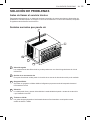
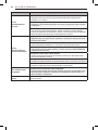
21 TROUBLESHOOTING
21 Before Calling for Service
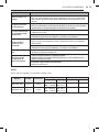
21 Normal Sounds You May Hear
20 MAINTENANCE
20 Air Filter

3
SAFETY INSTRUCTIONS
SAFETY INSTRUCTIONS
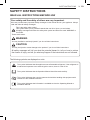
READ ALL INSTRUCTIONS BEFORE USE
Your safety and the safety of others are very important.
We have provided many important safety messages in this manual and on your appliance. Always
read and follow all safety messages.
This is the safety alert symbol.
This symbol alerts you to potential hazards that can kill or injure you and others.
All safety messages will follow the safety alert symbol and either the word WARNING or
CAUTION.
These words mean:
WARNING
You may be killed or seriously injured if you do not follow instructions.
CAUTION
You may be injured or cause damage to the product if you do not follow instructions.
All safety messages will tell you what the potential hazard is, tell you how to reduce
the chance of injury, and tell you what may happen if the instructions are not followed.
EN
The following symbols are displayed on units.
This symbol indicates that this appliance uses a flammable refrigerant. If the refrigerant is
is leaked and exposure to an external ignition source, there is a risk of fire.
This symbol indicates that the Operation Manual should be read carefully.
This symbol indicates that a service personnel should be handling this equipment with
reference to the Installation Manual.
This symbol indicates that information is available such as the Operating Manual or
Installation Manual.

4
SAFETY INSTRUCTIONS
●When the power cord is to be replaced, replacement work shall be performed by authorized
personnel only using only genuine replacement parts.
and authorized personnel only.
●Connect to a properly rated, protected, and sized power circuit to avoid electrical overload.
●Always plug into a grounded outlet.
●Do not under any circumstances, cut or remove the third (ground) prong from the power cord.
●When installing or moving the appliance, be careful not to pinch, crush, or damage the power
cord.
●Plug in the power plug properly.
●Do not modify or extend the power cord.
●Do not start/stop operation by plugging/unplugging the power cord.
●If the supply cord is damaged, it must be replaced by the manufacturer, its service agent or
similarly qualified person in order to avoid a hazard.
●Do not turn on the circuit breaker or power under condition that front grille, cabinet, control box
are removed or opened. Otherwise, it may cause fire, electric shock, explosion or death.
●Use a dedicated circuit.
●Do not disassemble or modify the product.
●Adhere to all industry recommended safety procedures including the use of long-sleeved gloves
and safety glasses.
●Use care when unpacking and installing. The edges of the product may be sharp.
●Disconnect the power cord or circuit breaker before installing or servicing the appliance.
●Keep packaging materials out of the reach of children. These materials can pose a suffocation
risk to children.
●Store and install the product where it will not be exposed to temperatures below freezing or
exposed to outdoor weather conditions.
other appliance.
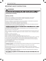
IMPORTANT SAFETY INSTRUCTIONS
WARNING
injury to persons when using this product, follow basic precautions,
including the following:
INSTALLATION
●Before use, the appliance must be properly installed as described in this manual.
●Contact the authorized service technician for repair or maintenance of this unit.
●Contact the installer for installation of this unit.
●The air conditioner is not intended for use by young children or invalids without supervision.
●Keep any required ventilation openings clear of obstruction.
●Compliance with national gas regulations shall be observed

5
SAFETY INSTRUCTIONS
●If water enters the product, turn off the power at the main circuit, then unplug the product and call
for service.
●If the product has been submerged, contact the LG Electronics Customer Information Center for
instructions before resuming use.
●Unplug the product when unused for long periods.
●Unplug the product before cleaning.
●In the event of a gas leak (propane gas, etc.) do not operate this or any other appliance. Open a
window or door to ventilate the area immediately.
●This appliance is not intended for use by persons (including children) with reduced physical,
sensory or mental capabilities, or lack of experience and knowledge, unless they have been
given supervision or instruction concerning the use of the appliance by a person responsible for
their safety. Children should be supervised to ensure that they do not play with the appliance.
●The interior of the product must only be cleaned by a LG Electronics Customer Information
Center or a dealer.
●Do not use solvent-based detergent on the product. Doing so can cause corrosion or damage,
GROUNDING INSTRUCTIONS
●The power cord of this appliance is equipped with a three-prong (grounding) plug. Use this with
a standard three-slot (grounding) wall power outlet to minimize the hazard of electric shock. The
sure the receptacle is properly grounded. DO NOT CUT OR REMOVE THE THIRD (GROUND)
PRONG FROM THE POWER PLUG.
●Attaching the adapter ground terminal to the wall receptacle cover screw does not ground the
appliance unless the cover screw is metal, and not insulated, and the wall receptacle is grounded
to make sure the receptacle is properly grounded.
●Disconnect the power cord from the adapter, using one hand on each. Otherwise, the adapter
ground terminal might break. Do not use the appliance with a broken adapter plug.
- Situations when the appliance will be disconnected often; Do not use an adapter plug in these
situations. Unplugging the power cord frequently can lead to an eventual breakage of the
ground terminal. The wall power outlet should be replaced by a three-slot (grounding) outlet
instead.
ytefas laitnetop fo esuaceB ;yllanoisacco detcennocsid eb lliw ecnailppa eht nehw snoitautiS-
hazards, we strongly discourage the use of an adapter plug.
EN
OPERATION
●Use this appliance only for its intended purpose.
●Never attempt to operate this appliance if it is damaged, malfunctioning, partially disassembled,
or has missing or broken parts, including a damaged cord or plug.
●Repair or immediately replace all power cords that have become frayed or otherwise damaged.
Do not use a cord that shows cracks or abrasion damage along its length or at either end.
●Do not run cord under carpets or mats where it could be stepped on and damaged.
●Keep the cord out from under heavy objects like tables or chairs.
●Do not place the power cord near a heat source.
●Do not use an adaptor or plug the product into a shared outlet.
●Do not tamper with controls.
●If you detect a strange sound, a chemical or burning smell, or smoke coming from the appliance,
unplug it immediately, and contact an LG Electronics Customer Information Center.
straight out from the outlet.
●Do not grasp the power cord or touch the appliance controls with wet hands.

6
SAFETY INSTRUCTIONS
CAUTION
To reduce the risk of minor or moderate injury to persons, malfunction, or
damage to the product or property when using this product, follow basic
precautions, including the following:
INSTALLATION
●Take care when installing the product that exhaust or condensation does not damage nearby
property.
●Follow installation instructions exactly to avoid excessive vibration or water leakage.
OPERATION
●This appliance is not intended for use as a precision refrigeration system. Do not use it for special
purposes such as maintaining pets, food, precision machinery, or art objects.
●When installing or moving the appliance, be careful not to pinch, crush, or damage the power
cord.
●Make sure the air inlet and outlet are free from obstructions.
●Use a soft cloth to clean the appliance. Do not use waxes, thinners, or harsh detergents.
●Do not step on or place heavy objects on top of the appliance.
●Do not drink water drained from the appliance.
are used simultaneously.
●Remove the batteries if the remote control is not to be used for an extended period of time.
●Never mix different types of batteries, or old and new batteries for the remote control.
consult a doctor.
●Do not recharge or disassemble the batteries.
MAINTENANCE
●Never use strong cleaning agents or solvents when cleaning the air conditioner or spray water.
Use a smooth cloth.
●Do not install the appliance in an area where it is directly exposed to sea air (salt spray).
− Saline conditions are a cause of corrosion. (Particularly, corrosion of the condenser and
●Set up windbreak in front of the outdoor unit if installing it in coastal areas.
− Avoid direct exposure to salt winds.
− Install a firm and stiff concrete-wind shield that can withstand salt winds.
evaporator can damage the appliance or impair its performance.)

7
SAFETY INSTRUCTIONS
Prior to beginning work on systems containing flammable refrigerants, safety checks are necessary to ensure
that the risk of ignition is minimised. For repair to the refrigerating system, the following precautions shall be
complied with prior to conducting work on the system.
IMPORTANT SAFETY INSTRUCTIONS
WARNING
Checks to the area
Work shall be undertaken under a controlled procedure so as to minimise the risk of a flammable gas or
vapour being present while the work is being performed.
Work procedure
All maintenance staff and others working in the local area shall be instructed on the nature of work being
carried out. Work in confined spaces shall be avoided. The area around the workspace shall be sectioned off.
Ensure that the conditions within the area have been made safe by control of flammable material.
General work area
The area shall be checked with an appropriate refrigerant detector prior to and during work, to ensure the
technician is aware of potentially flammable atmospheres. Ensure that the leak detection equipment being
used is suitable for use with flammable refrigerants, i.e. non-sparking, adequately sealed or intrinsically safe.
Checking for presence of refrigerant
If any hot work is to be conducted on the refrigeration equipment or any associated parts, appropriate fire
extinguishing equipment shall be available to hand. Have a dry powder or CO2 fire extinguisher adjacent to
the charging area.
Presence of fire extinguisher
No person carrying out work in relation to a refrigeration system which involves exposing any pipe work that
contains or has contained flammable refrigerant shall use any sources of ignition in such a manner that it may
lead to the risk of fire or explosion. All possible ignition sources, including cigarette smoking, should be kept
sufficiently far away from the site of installation, repairing, removing and disposal, during which flammable
refrigerant can possibly be released to the surrounding space. Prior to work taking place, the area around the
equipment is to be surveyed to make sure that there are no flammable hazards or ignition risks.
“No Smoking” signs shall be displayed.
No ignition sources
Ensure that the area is in the open or that it is adequately ventilated before breaking into the system or
conducting any hot work. A degree of ventilation shall continue during the period that the work is carried out.
The ventilation should safely disperse any released refrigerant and preferably expel it externally into the
atmosphere.
Ventilated area
Where electrical components are being changed, they shall be fit for the purpose and to the correct
specification. At all times the manufacturer’s maintenance and service guidelines shall be followed. If in doubt
consult the manufacturer’s technical department for assistance.
The following checks shall be applied to installations using flammable refrigerants:
– The actual refrigerant charge is in accordance with the room size within which the refrigerant containing
parts are installed.
– The ventilation machinery and outlets are operating adequately and are not obstructed.
– If an indirect refrigerating circuit is being used, the secondary circuit shall be checked for the presence
of refrigerant.
– Marking to the equipment continues to be visible and legible. Markings and signs that are illegible shall be
corrected.
– Refrigeration pipe or components are installed in a position where they are unlikely to be exposed to any
substance which may corrode refrigerant containing components, unless the components are constructed of
materials which are inherently resistant to being corroded or are suitably protected against being so corroded.
Checks to the refrigeration equipment
Repair and maintenance to electrical components shall include initial safety checks and component inspection
procedures. If a fault exists that could compromise safety, then no electrical supply shall be connected to the
circuit until it is satisfactorily dealt with. If the fault cannot be corrected immediately but it is necessary to
continue operation, an adequate temporary solution shall be used. This shall be reported to the owner of the
equipment so all parties are advised.
Checks to electrical devices
EN

8
SAFETY INSTRUCTIONS
Initial safety checks shall include:
– Capacitors are discharged: this shall be done in a safe manner to avoid possibility of sparking.
– No live electrical components and wiring are exposed while charging, recovering or purging the system.
– Continuity of earth bonding.
During repairs to sealed components, all electrical supplies shall be disconnected from the equipment being
worked upon prior to any removal of sealed covers, etc.
Particular attention shall be paid to the following to ensure that by working on electrical components, the
casing is not altered in such a way that the level of protection is affected.
This shall include damage to cables, excessive number of connections, terminals not made to original
specification, damage to seals, incorrect fitting of glands, etc.
Ensure that apparatus is mounted securely.
Ensure that seals or sealing materials have not degraded such that they no longer serve the purpose of
preventing the ingress of flammable atmospheres.
Replacement parts shall be in accordance with the manufacturer’s specifications.
If it is absolutely necessary to have an electrical supply to equipment during servicing, then a permanently
operating form of leak detection shall be located at the most critical point to warn of a potentially hazardous
situation.
Repairs to sealed components
When breaking into the refrigerant circuit to make repairs – or for any other purpose – conventional procedures
shall be used. However, it is important that best practice is followed since flammability is a consideration.
The following procedure shall be adhered to:
– Remove refrigerant.
– Purge the circuit with inert gas.
– Evacuate.
– Purge again with inert gas.
– Open the circuit by cutting or brazing.
Do not apply any permanent inductive or capacitance loads to the circuit without ensuring that this will not
exceed the permissible voltage and current permitted for the equipment in use.
Intrinsically safe components are the only types that can be worked on while live in the presence of a flammable
atmosphere.
The test apparatus shall be at the correct rating.
Replace components only with parts specified by the manufacturer.
Other parts may result in the ignition of refrigerant in the atmosphere from a leak.
Repair to intrinsically safe components
Cabling will not be subject to wear, corrosion, excessive pressure, vibration, sharp edges or any other adverse
environmental effects. The check shall also take into account the effects of ageing or continual vibration from
sources such as compressors or fans.
Cabling Check
Under no circumstances shall potential sources of ignition be used in the searching for or detection of
refrigerant leaks. A halide torch (or any other detector using a naked flame) shall not be used.
Detection of flammable refrigerants
The following leak detection methods are deemed acceptable for systems containing flammable refrigerants.
Ensure that the detector is not a potential source of ignition and is suitable for the refrigerant used.
If a leak is suspected, all naked flames shall be removed/extinguished.
Oxygen free nitrogen (OFN) shall then be purged through the system both before and during the brazing process.
If a leakage of refrigerant is found which requires brazing, all of the refrigerant shall be recovered from the
system, or isolated (by means of shut off valves) in a part of the system remote from the leak.
Leak detection fluids are suitable for use with most refrigerants but the use of detergents containing chlorine
shall be avoided as the chlorine may react with the refrigerant and corrode the copper pipe-work.
Leak detection equipment shall be set at a percentage of the LFL of the refrigerant and shall be calibrated to the
refrigerant employed and the appropriate percentage of gas (25 % maximum) is confirmed.
Electronic leak detectors shall be used to detect flammable refrigerants, but the sensitivity may not be adequate,
or may need re-calibration. (Detection equipment shall be calibrated in a refrigerant-free area.)
Leak detection methods
Removal and evacuation

9
SAFETY INSTRUCTIONS
– Ensure that contamination of different refrigerants does not occur when using charging equipment. Hoses or
lines shall be as short as possible to minimise the amount of refrigerant contained in them.
– Cylinders shall be kept upright.
– Ensure that the refrigeration system is earthed prior to charging the system with refrigerant.
– Label the system when charging is complete (if not already).
– Extreme care shall be taken not to overfill the refrigeration system. Prior to recharging the system it shall be
pressure tested with OFN. The system shall be leak tested on completion of charging but prior to
commissioning. A follow up leak test shall be carried out prior to leaving the site.
The refrigerant charge shall be recovered into the correct recovery cylinders. The system shall be “flushed” with
OFN to render the unit safe. This process may need to be repeated several times. Compressed air or oxygen
shall not be used for this task. Flushing shall be achieved by breaking the vacuum in the system with OFN and
continuing to fill until the working pressure is achieved, then venting to atmosphere, and finally pulling down to a
vacuum. This process shall be repeated until no refrigerant is within the system. When the final OFN charge is
used, the system shall be vented down to atmospheric pressure to enable work to take place. This operation is
absolutely vital if brazing operations on the pipe-work are to take place. Ensure that the outlet for the vacuum
pump is not close to any ignition sources and there is ventilation available.
In addition to conventional charging procedures, the following requirements shall be followed.
Charging procedures
Before carrying out this procedure, it is essential that the technician is completely familiar with the equipment
and all its detail.
It is recommended good practice that all refrigerants are recovered safely.
Prior to the task being carried out, an oil and refrigerant sample shall be taken in case analysis is required
prior to re-use of reclaimed refrigerant. It is essential that electrical power is available before the task is
commenced.
a) Become familiar with the equipment and its operation.
b) Isolate system electrically.
d) Pump down refrigerant system, if possible.
f ) Make sure that cylinder is situated on the scales before recovery takes place.
g) Start the recovery machine and operate in accordance with manufacturer's instructions.
h) Do not overfill cylinders. (No more than 80 % volume liquid charge).
i ) Do not exceed the maximum working pressure of the cylinder, even temporarily.
k) Recovered refrigerant shall not be charged into another refrigeration system unless it has been cleaned
and checked.
j ) When the cylinders have been filled correctly and the process completed, make sure that the cylinders
and the equipment are removed from site promptly and all isolation valves on the equipment are closed off.
e) If a vacuum is not possible, make a manifold so that refrigerant can be removed from various parts of
the system.
c) Before attempting the procedure ensure that:
Decommissioning
Equipment shall be labelled stating that it has been de-commissioned and emptied of refrigerant. The
label shall be dated and signed. Ensure that there are labels on the equipment stating the equipment
contains flammable refrigerant.
Labelling
EN

10
SAFETY INSTRUCTIONS
When removing refrigerant from a system, either for servicing or decommissioning, it is recommended
good practice that all refrigerants are removed safely.
When transferring refrigerant into cylinders, ensure that only appropriate refrigerant recovery cylinders are
employed. Ensure that the correct number of cylinders for holding the total system charge are available.
All cylinders to be used are designated for the recovered refrigerant and labelled for that refrigerant
(i.e. special cylinders for the recovery of refrigerant). Cylinders shall be complete with pressure relief valve
and associated shut-off valves in good working order. Empty recovery cylinders are evacuated and, if
possible, cooled before recovery occurs. The recovery equipment shall be in good working order with a set
of instructions concerning the equipment that is at hand and shall be suitable for the recovery of flammable
refrigerants. In addition, a set of calibrated weighing scales shall be available and in good working order.
Hoses shall be complete with leak-free disconnect couplings and in good condition. Before using the
recovery machine, check that it is in satisfactory working order, has been properly maintained and that any
associated electrical components are sealed to prevent ignition in the event of a refrigerant release. Consult
manufacturer if in doubt. The recovered refrigerant shall be returned to the refrigerant supplier in the correct
recovery cylinder, and the relevant Waste Transfer Note arranged. Do not mix refrigerants in recovery units
and especially not in cylinders. If compressors or compressor oils are to be removed, ensure that they have
been evacuated to an acceptable level to make certain that flammable refrigerant does not remain within the
lubricant. The evacuation process shall be carried out prior to returning the compressor to the suppliers.
Only electric heating to the compressor body shall be employed to accelerate this process. When oil is
drained from a system, it shall be carried out safely.
Recovery

11
SAFETY INSTRUCTIONS
REFRIGERANT (FOR R32 ONLY)
WARNING
●Do not use means to accelerate the defrosting process or to clean, other than those
recommended by the manufacturer.
●The appliance shall be stored in a room without continuously operating open flames (for example
●Servicing shall only be performed as recommended by the equipment manufacturer.
●The appliance shall be stored so as to prevent mechanical damage from occurring.
an operating gas appliance) and ignition sources (for example an operating electric heater).
●The appliance shall be stored in a well-ventilated area where the room size corresponds to the
room area as specified for operation.
current valid certificate from an industry-accredited assessment authority, which authorises their
Technical Safety
●Any person who is involved with working on or breaking into a refrigerant circuit should hold a
competence to handle refrigerants safely in accordance with an industry recognised assessment
specification.
Maintenance and repair requiring the assistance of other skilled personnel shall be carried out
under the supervision of the person competent in the use of flammable refrigerants.
EN

12
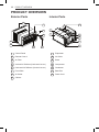
PRODUCT OVERVIEW
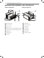
PRODUCT OVERVIEW
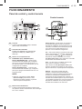
Exterior Parts Interior Parts
8
6
2
3
1
4
5
7
3
4
5
6
7
1
2
1
Evaporator
2
Air Guide
3
4
Brace
5
Compressor
6
Condenser
Vertical Air Deflector (Horizontal Louver)
Horizontal Air Deflector (Vertical Louver)
7
Base Pan
Power Cord
1
Control Panel
2
Remote Control
3
Air Filter
4
5
6
Front Grille
7
8
Cabinet
Air Outlet

13
INSTALLATION
EN
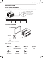
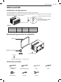
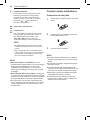
Circuit Breaker Installation
Installation Overview
Drain pan
Screw
(For Front Grille, L: 10 mm, 2 EA)
( )
Foam
(L: 30 mm, 5 EA )
Tools Needed
Phillips-head
screwdriver
Flat-blade screwdriver LevelPencil
Tape measure Cutting knife Scissors
Main Power source
Circuit Breaker
Use a circuit breaker
or time delay fuse.
Read thoroughly and follow all directions provided.
A circuit breaker must be installed between the power source and the unit if the plug is not used
(see illustration below).
NOTE
INSTALLATION
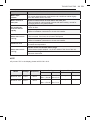
Model Voltage Frequency
W121CE SL0 115 V~ 60 Hz 20 A
W122CE SL0 220 V~ 60 Hz 15 A
Circuit Breaker

14
INSTALLATION
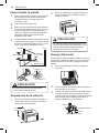
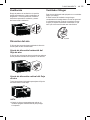
How to Install the Unit
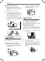
Preparation of the Cabinet
1
Remove 4 screws which fasten the cabinet
at both sides and at the back. (Keep the
screws for later use.)
1
Measure the space for installation to assure
a good fit. The air conditioner must be
2
Avoid exposure to direct sunlight.
installed firmly into place to prevent vibration
and noise.
1
Remove the rubber cap from the hole under
the base-pan.
cabinet with 2-4 screws.
2
Install the drain pan over the corner of the
on the bottom of the drain pan. (You can
3
Connect the drain hose to the outlet located
satisfy your particular needs. Drain hose is not
supplied)
purchase the drain hose or tubing locally to
There must be at least 50 cm (20 in.) of
cleared space around the rear of the unit.
Obstacles restricting the airflow may reduce
the cooling efficiency of the unit.
3
Remove all obstacles from the rear of the unit.
towards the outside to allow condensed water
to drain. (About 10~15 mm or 1/4 bubble with
Level)
4
The unit should be installed with a slight tilt
Shipping
Fence
Awning
Heat
radiation
Cooled air
Screws
2
Slide the unit from the cabinet by gripping
the base pan handle and pulling forward
while bracing the cabinet.
CAUTION
●The unit is heavy. To prevent injury, use
proper lifting techniques when pulling unit
forward from cabinet. Obtain assistance
from another person if possible.
CAUTION
●The external grille must be exposed outside
for air discharge.
10~15 mm
Over 50 cm
Foam
70-150 cm
Level
1/4 Bubble
Drainage (Optional)
To drain the excess water, remove the drain cap
The base-pan may overflow due to high humidity.
from the base pan of the unit and secure the Drain
Pan.
Cabinet
Drain Hose
Screw
Drain Pan

15
INSTALLATION
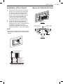
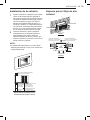
Installation of the Cabinet Space for Outside Air Flow
NOTE
bottom of the cabinet is well supported,
the top has minimum clearace and the
air inlet louveres have clearance as
shown. Holes from the outside through
to the cavity should be sealed. The
cabinet should slope down towards
the rear by about 10~15 mm to allow
water formed during operation to drain.
1
Prepare the hole in the wall so that the
secure. Ensure the foam seals are not
damaged. Flash, seal or fill gaps around
the inside and outside to provide
satisfactory appearance and protection
against the weather, insects and rodents.
2
Install the cabinet into the wall and
●Unit may be supported by a solid frame from
below or by a hanger from a solid overhead
support.
FLASH OR SEAL AROUND EXTERNAL
WALL FRAME OR ARCHITRAVE
STURDY TIMBER
FRAME ALL ROUND
UNIT
DRAIN CHUTE
EXTERNAL SUPPORT
FRAME AT BALANCE
POINT OF RAC
Preferred method of installation into
a timber framed wall, partition or window.
ALTERNATIVELY, BRACKETS
AS ILLUSTRATED BELOW
MAY BE USED.
TIMBER FRAMED
WALL OR PARTITION
100 mm minimum
AIR IN
AIR IN
AIR OUT
OPTION A
100 mm
100 mm
LOUVRE
FRONT
45° BRICK CUT AWAY
TO CLEAR LOUVRES
45° BRICK CUT AWAY
TO CLEAR LOUVRES
BRICK
WALL
AIR INAIR IN
BRICK
WALL
AIR OUT
TOP
VIEW
OPTION B
EN

16
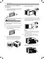
INSTALLATION
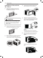
1
Slide the air conditioner into the case.
Reinstall the 2 screws removed earlier
on each side of the case.
2
Stuff the foam around the unit to prevent air
and insects from getting into the room.
3
Before installing the front grille, pull out the
vent control lever located above the unit
control knobs, as shown. (for some models)
CAUTION
●The unit is heavy. Use an assistant to help
lift the unit and set it in place. Lifting and
maneuvering the unit by yourself could
result in injury.
Screw
Screw
The Foam
4
Connect the wire harness from the front
grille assembly to the air conditioner.
5
Attach the front grille assembly to the
cabinet by inserting the grille tabs into the
slots on the front of the cabinet. Push the
grille in until it snaps into place.
NOTE
●Carefully guide the vent control lever
through the grille as you push the grille in.
6
Remove air filter from the front grille by
pulling the filter forward and then up
slightly.
Insert 2 type A screws through the front
grille.
Installations of the unit into
the Cabinet

17
OPERATION
OPERATION
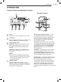
Control Panel and Remote Control
EN
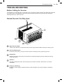
Remote Control
1
Power
Press to turn the air conditioner ON or OFF.
2
Fan Speed
Press to set the fan speed to Low (Bajo) (F1),
Medium (Medio) (F2) or High (Alto) (F3).
3
Delay ON/OFF Timer
Delay ON - When the air conditioner is off,
set it to automatically turn on from 1 to 24
hours later, at its previous mode and fan
settings.
Delay OFF - When the air conditioner is on,
set it to automatically turn off from 1 to 24
hours later.
NOTE
●Each press of the Timer (Control Tiempo
)
,
button advances the timer by 1 hour. After
the last press the display returns to the
temperature setting.
4
Operation Mode
Press the Mode (Modo) button to cycle
between 4 types of air conditioner operation:
Energy Saver (Ahorro Energía) / Cool (Frío) /
Fan (Vent.) / Dry (Deshum).
Cool (Frío)
Fan (Vent.) - In this mode the fan circulates
air but the compressor does not run. Use
the Fan Speed (Nivel Vent.) button to set
speed to High, Medium or Low. In this mode,
you cannot adjust the set temperature.
Dry (Deshum) - This mode is ideal for rainy
and damp days to dehumidify the room rather
than cooling it significantly. Humidity is
removed from the room by the combination
of compressor operation and the fan speed
fixed at Low. The compressor and fan turn
off once the set temperature is reached.
Fan speed cannot be adjusted in Dry (Deshum)
mode.
1
4
2
5
3
- This mode is ideal on hot days
to cool and dehumidify the room quickly. Use
the Temp
buttons to set the desired
room temperature and use the Fan Speed
(Nivel Vent.)
button to set the desired fan
circulation speed.
Energy Saver (Ahorro Energía) - In this
the compressor and fan turn off when the
set temperature is achieved. Approximately
every 3 minutes the fan turns on to allow
the unit sensor to accurately determine if
more cooling is needed.
7
1234
5
6

18
OPERATION
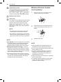
Wireless Remote Control
Inserting Battery
1
Push out the cover on the back of the
remote control with your thumb.
2
With the plus and minus poles facing as
marked, and insert one new AAA 1.5 V
battery.
3
Reattach the cover.
NOTE
●One new battery are supplied with the air
conditioner for use in the remote control.
●Do not use a rechargeable battery. Make sure
that the battery is new.
●In order to prevent discharge, remove the
battery from the remote control if the air
conditioner is not going to be used for an
extended period of time.
●Keep the remote control away from extremely
hot or humid places.
●To maintain optimal operation of the remote
control, the remote sensor should not be
exposed to direct sunlight.
5
Temperature Control
The thermostat monitors room temperature
to maintain the desired temperature. The
thermostat can be set between 16 °C–30 °C
(60 °F–86 °F). Press
or
arrows to
increase or decrease temperature setting.
6
Remote Control Sensor
Clean Filter
The Clean Filter (Limpieza Filtro) LED lights
up to notify you that the filter needs to be
cleaned. After cleaning the filter, press
Temp
and together on the control
panel to turn off the Clean Filter (Limpieza
Filtro) light.
NOTE
control panel, not the remote control.
●
●
This feature is a reminder to clean the air
light turns on after 250 hours of operation.
filter for more efficient operation. The LED
The filter reset must be done using the
7
NOTE
●Auto Restart: If the air conditioner turns off due
to a power outage, it will restart automatically
once the power is restored, with the same
settings as were set before the unit turned off.
●Energy Saver (Ahorro Energía) : The unit
defaults to the Energy Saver (Ahorro Energía)
mode each time the unit is switched on except
in Fan (Vent.) mode or when power is restored
after an electrical power outage.
●The remote control will not function properly if
the AC infrared sensor is exposed to direct light
or if there are obstacles between the remote
controller and the air conditioner.
.

19
OPERATION
EN
Close Open
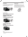
Air Direction
Ventilation
Push the ventilation lever in to the closed position
to maintain the best cooling performance. Pull
the ventilation lever out to open the vent and
draw fresh air into the room.
of the air conditioner’s louvers.
Direction
levers of the vertical louvers to the left or right.
Direction
up or down.
NOTE
●When the weather is extremely hot, the unit
may turn off automatically to protect the
compressor.
Slinger Fan
This air conditioner is equipped with a slinger
fan. (See drawing.)
The fan’s outer ring picks up the condensed
water from the base pan if the water level gets
high enough. The water is then picked up by the
fan and expelled through the condenser, making
the air conditioner more efficient.
Ring

20
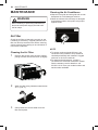
MAINTENANCE
MAINTENANCE
WARNING
Before cleaning or performing maintenance,
disconnect the power supply and wait until
the fan stops.
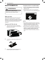
Air Filter
Check the air filter at least twice a month to see
if cleaning is necessary. Trapped particles in the
filter can build up and block the airflow, reducing
cooling capacity and causing an accumulation of
frost on the evaporator.
Cleaning the Air Filter
Cleaning the Air Conditioner
●Wipe the front grille and inlet grille with a cloth
dampened in a mild detergent solution.
●Wash the cabinet with mild soap or detergent
and lukewarm water, then polish using liquid
appliance wax.
NOTE
●
condenser coils (outside of unit) should be
To ensure continued peak efficiency, the
checked periodically and cleaned if clogged
with soot or dirt from outside air.
●For repair and maintenance, contact a
LG Electronics Customer Information Center.
See the warranty card for details or call
55-5321-1919. Have your model number and
serial number available.
2
Wash the filter using lukewarm water below
40 °C (104 °F).
Remove the air filter from the front grille by
pulling the filter forward and then up slightly.
3
Gently shake the excess water from the
filter and replace.
1
Page is loading ...
Page is loading ...
Page is loading ...
Page is loading ...
Page is loading ...
Page is loading ...
Page is loading ...
Page is loading ...
Page is loading ...
Page is loading ...
Page is loading ...
Page is loading ...
Page is loading ...
Page is loading ...
Page is loading ...
Page is loading ...
Page is loading ...
Page is loading ...
Page is loading ...
Page is loading ...
Page is loading ...
Page is loading ...
Page is loading ...
Page is loading ...
Page is loading ...
Page is loading ...
Page is loading ...
Page is loading ...
-
 1
1
-
 2
2
-
 3
3
-
 4
4
-
 5
5
-
 6
6
-
 7
7
-
 8
8
-
 9
9
-
 10
10
-
 11
11
-
 12
12
-
 13
13
-
 14
14
-
 15
15
-
 16
16
-
 17
17
-
 18
18
-
 19
19
-
 20
20
-
 21
21
-
 22
22
-
 23
23
-
 24
24
-
 25
25
-
 26
26
-
 27
27
-
 28
28
-
 29
29
-
 30
30
-
 31
31
-
 32
32
-
 33
33
-
 34
34
-
 35
35
-
 36
36
-
 37
37
-
 38
38
-
 39
39
-
 40
40
-
 41
41
-
 42
42
-
 43
43
-
 44
44
-
 45
45
-
 46
46
-
 47
47
-
 48
48


LG W122CE Owner's manual
- Type
- Owner's manual
- This manual is also suitable for
Ask a question and I''ll find the answer in the document
Finding information in a document is now easier with AI
in other languages
- español: LG W122CE El manual del propietario
Related papers
Other documents
-
Taurus Alpatec DH 1201 Owner's manual
-
-
Taurus HOME AC 2600 Owner's manual
-
mundoclima Series MUPO-C9/H9 Installation guide
-
-
-
EAS ELECTRIC EHD20DA User manual
-
Dimplex DPRC20ECO-A Portable Air Conditioner User manual
-
Svan SVAN2009 Owner's manual
-
Rowenta RWAC9000C User manual