Page is loading ...

Table of Contents
Cover photo may show optional equipment not supplied
with standard unit.
Read the Operator’s Manual entirely. When you see this symbol,
the subsequent instructions and warnings are serious - follow
without exception. Your life and the lives of others depend on it!
!
Water Spray Kit
For CP30 Series Cold Planers and SW30 Series Road Saws
350-454MK
Operator’s Manual
Printed 06/17/20
73108

Introduction
6/17/20Water Spray Kit For CP30 Series Cold Planers and SW30 Series Road Saws Water Spray Kit 350-454MK
I
Table of Contents
Introduction
To the Purchaser
All products are designed to give safe, dependable
service if they are operated and maintained according to
instructions. Read and understand this manual before
operation, and keep it in your files for further reference.
This manual has been prepared to assist the owner and
operators in the safe operation and suitable maintenance
of the equipment. The information is applicable to
products at the time of manufacture and does not include
modifications made afterwards.
Read and understand this Operator’s Manual before
attempting to put equipment into service. Familiarize
yourself with the operating instructions and all the safety
recommendations contained in this manual and those
labeled on the equipment and on the power machine.
Follow the safety recommendations and make sure that
those with whom you work follow them. Not following
them could result in serious personal injury or equipment
damage. If you have any questions consult your dealer.
Product Identification
To assist your dealer in handling your needs, please
record hereafter the model number of your equipment. It
is also advisable to supply them to your insurance
company. It will be helpful in the event that the equipment
or power machine is lost or stolen.
To the Dealer
Give this manual to the owner upon delivery of the
equipment.
To the Purchaser and Dealer
Illustrations
The illustrations may not necessarily reproduce the full
detail and the exact shape of the parts or depict the
actual models, but are for reference only.
Direction Reference
All references to right and left, front, or back are from the
operator seat while facing the direction the machine will
operate.
Directional Arrows Used in Illustrations
U = up, D = down, L = left,
R = right, F = front, and B = back
U
D
R
L
F
B
Dealer Contact Information
Model Number:
Serial Number:
Date of Purchase:
Dealer Name:
Street:
City/State:
Telephone:
Email:

Introduction
Water Spray Kit For CP30 Series Cold Planers and SW30 Series Road Saws Water Spray Kit 350-454MK6/17/20
II
Table of Contents
Legal Disclaimer
Kubota Tractor Corporation notes that specifications and technical information are subject to change without notice and
Kubota Tractor does not represent or warrant that the information in this publication is completely accurate or current;
however, Kubota Tractor used reasonable efforts to set forth and include accurate and up to date information in this
publication. Kubota Tractor disclaims all representations and warranties, whether express or implied, including, but not
limited to, warranties of merchantability and fitness for a particular purpose and Kubota Tractor shall not be liable for any
damages, whether compensatory, direct, indirect, incidental, special, or consequential, arising out of or in connection
with the use of this publication, or in the information therein.
The Product(s) described in this Publication are designed and manufactured only for the country in which they are
initially wholesaled by Kubota Tractor. Kubota Tractor does not provide parts, warranty or service for any Product which
is re-sold or retailed in any country other than the country for which the Product(s) were designed or manufactured.
Safety First
This symbol, the industry’s “Safety Alert Symbol”, is used throughout this manual and on labels on the machine
itself to warn of the possibility of personal injury. Read these instructions carefully. It is essential that you read
the instructions and safety regulations before you attempt to assemble or use this unit.
DANGER:
!
WARNING:
CAUTION:
!
!
Indicates an imminently hazardous situation which, if not avoided, will result in death or
serious injury.
Indicates a potentially hazardous situation which, if not avoided, could result in death or
serious injury.
Indicates a potentially hazardous situation which, if not avoided, may result in minor or
moderate injury.
Indicates that equipment or property damage could result if instructions are not followed.
Gives helpful information.
IMPORTANT:
NOTE:
!
WARNING: Cancer and reproductive harm - www.P65Warnings.ca.gov
!
California Proposition 65

Table of Contents
Water Spray Kit For CP30 Series Cold Planers and SW30 Series Road Saws 350-454MK6/17/20
III
Table of Contents
Introduction . . . . . . . . . . . . . . . . . . . . . . . . . . . .I
To the Purchaser . . . . . . . . . . . . . . . . . . . . . . . . . . .I
Product Identification . . . . . . . . . . . . . . . . . . . . . . .I
Dealer Contact Information . . . . . . . . . . . . . . . . . .I
To the Dealer . . . . . . . . . . . . . . . . . . . . . . . . . . . . . .I
To the Purchaser and Dealer . . . . . . . . . . . . . . . . . .I
Illustrations . . . . . . . . . . . . . . . . . . . . . . . . . . . . . .I
Direction Reference . . . . . . . . . . . . . . . . . . . . . . . .I
Section 1: Installation . . . . . . . . . . . . . . . . . . . 1
Before You Start . . . . . . . . . . . . . . . . . . . . . . . . . . . 1
Parts List . . . . . . . . . . . . . . . . . . . . . . . . . . . . . . . . . 1
Torque Requirements . . . . . . . . . . . . . . . . . . . . . . . 1
Further Assistance . . . . . . . . . . . . . . . . . . . . . . . . . 1
Pre-Installation Safety . . . . . . . . . . . . . . . . . . . . . . . 1
Installation Instructions . . . . . . . . . . . . . . . . . . . . . . 2
Water Tank Installation . . . . . . . . . . . . . . . . . . . . . . 2
Cold Planer Spray Bar Installation . . . . . . . . . . . . . 3
Road Saw Spray Bar Installation . . . . . . . . . . . . . . . 4
Zip Ties . . . . . . . . . . . . . . . . . . . . . . . . . . . . . . . . . . 5
Section 2: Parts List . . . . . . . . . . . . . . . . . . . . 6
Water Tank Kit, CP30 #350-378A . . . . . . . . . . . . . . 6
Cold Planer Spray Bar Kit . . . . . . . . . . . . . . . . . . . . 7
Road Saw Spray Bar Kit . . . . . . . . . . . . . . . . . . . . . 8
Section 3: Torque Values Chart . . . . . . . . . . . 9

Section 1: Installation
Water Spray Kit For CP30 Series Cold Planers and SW30 Series Road Saws 350-454MK6/17/20
1
Table of Contents
Before You Start
Kubota welcomes you to the growing family of new
product owners. Your Water Tank & Spray Bar Kit is
exclusively designed for the Kubota CP30 Series Cold
Planers and SW30 Series Road Saws.
The Water Spray Kit is a high quality product built by
skilled workers using quality materials. Proper assembly,
maintenance, and safe operating practices will help you
get years of satisfactory use from this product.
The instructions contained within this manual provide
information required to assemble, operate, and maintain
the Water Spray Kit. It is important to follow the
installation steps closely. Not following the instructions
completely will adversely affect the durability of the Water
Tank Spray Kit and skid steer.
Refer to the skid steer Operator’s Manual for additional
information relating to safety concerns. Also included in
the Operator’s Manual is important information on
operation, adjustment, troubleshooting, and
maintenance of the skid steer and attachments.
To order a new Operator’s or Parts Manual, contact your
authorized dealer. Manuals can also be downloaded,
free-of-charge, from our website at www.landpride.com.
Have model and serial numbers handy when placing an
order.
Manual Part Numbers:
• Road Saw Operator’s Manual . . . . . . . 350-386MK
• Cold Planer Operator’s Manual . . . . . . 350-376MK
• Road Saw Parts Manual . . . . . . . . . . . 350-386PK
• Cold Planer Parts Manual . . . . . . . . . . .350-376PK
These assembly instructions apply to the following Water
Tank & Spray Bar Kit Accessories listed below:
350-378A WATER TANK KIT, CP30
350-379A SPRAY BAR KIT, CP3012LF
350-380A SPRAY BAR KIT, CP3016LF
350-381A SPRAY BAR KIT, CP3018
350-382A SPRAY BAR KIT, CP3024
350-383A SPRAY BAR KIT, CP3030
350-384A SPRAY BAR KIT, CP3040
350-385A SPRAY BAR KIT, CP3048
350-390A SPRAY BAR KIT, AP-SW30
Parts List
The Parts List on pages 6-8 provides a detailed listing of
parts. Use this list as a checklist to inventory parts
received. Please contact your local Kubota dealer for any
missing hardware.
When you see this symbol, the subsequent
instructions and warnings are serious - follow
without exception. Your life and the lives of
others depend on it!
!
For easy cross-referencing, the balloons with numbers in
the illustrations match item numbers in the Parts List.
Balloons with letters represent components other than
the Water Spray Kit.
Torque Requirements
Refer to “Torque Values Chart” on page 9 to determine
correct torque values for common bolts.
Further Assistance
Your Kubota dealer wants you to be satisfied with your
new Water Tank & Spray Bar Kit. If for any reason you do
not understand any part of this manual or are not
satisfied with the service received, the following actions
are suggested:
1. Discuss any problems you have with your accessory
with your dealership service personnel so they can
address the problem.
2. If you are still not satisfied, seek out the owner or
general manager of the dealership, explain the
question/problem, and request assistance.
3. For further assistance write to:
Kubota by Land Pride
Service Department
1525 East North Street
P.O. Box 5060
Salina, Ks. 67402-5060
E-mail address
lpservicedep[email protected]
Pre-Installation Safety
All installation procedures listed within this manual
are generally representative of the machine models
for which the manual is written. Your machine may be
configured differently, but the outline for the procedure
should still be followed. For further support of any issues
not covered within the pages of this manual, please
contact your local Kubota dealer.
1. Never allow unqualified personnel to install or
operate the Water Spray Kit.
2. Park the skid steer on a clean, flat, and dry surface
before performing any work on the skid steer or
Water Spray Kit.
3. Shut off the skid steer engine and remove its switch
key before installing the kit. Refer to your skid steer
Operator’s Manual for proper shutdown procedures.
4. Read and understand all applicable installation
manuals, owner's manuals, and warnings specific to
the equipment being used and/or worked on.
5. Wear proper safety equipment such as safety
goggles, protective gloves, safety boots, hardhat,
etc., as appropriate or required.
Section 1: Installation

Section 1: Installation
Water Spray Kit For CP30 Series Cold Planers and SW30 Series Road Saws 350-454MK 6/17/20
2
Table of Contents
Water Tank Kit Installation
Figure 1
72652
U
D
R
L
F
B
L
e
ft
R
ig
h
t
Installation Instructions
Refer to Figure 1:
WARNING
!
To avoid serious injury or death: The tank assembly is heavy
and difficult for one person to locate on top of the cab. Use a
hoist or additional people to help place the tank assembly on
top of the skid steer cab.
IMPORTANT: Route Hose and shut off valve to clear
loader arms leaving enough slack to allow for the tilt,
depth and side shift functions of the Cold Planer or
Road Saw.
NOTES:
• Teflon tape should be used on the threaded
connections.
• Tank supports (#12) are used with narrow cabs and
supports (#14) with wide cabs.
• 1/2” ID Vinyl tubing (#1) is furnished in one coiled
length and must be cut to various lengths to suit.
Water Tank Installation
Refer to Figure 1:
1. Install the two side tank supports (#12 or #14) to tank
support (#11) with 1/2" bolts (#17), flat washers (#19)
and hex nuts (#18).
2. Place the assembled tank cradle on top of the loader
cab. If applicable, make sure bolts (#17) do not hit the
roof window).
3. Place tank (#7) in the tank cradle and secure with
bungee cords (#16) as shown.
4. Install two ratchet straps (#15) from front to back as
shown. Draw straps up tight.
5. If not installed, install 3/4” pipe threaded bulkhead
fitting (#9) to tank (#7) and 3/4” male plastic fitting
with 1/2" barb (#2) to bulkhead fitting (#9) as shown.
Draw bulkhead and barb fittings up tight.
6. Attach one end of vinyl tubing (#1) to plastic
fitting (#2) with hose clamp (#8).
7. Run vinyl tube (#1) along the front left corner of the
cab to a length ideal for mounting shut-off
ball valve
(#13). Cut vinyl tubing to length.

Section 1: Installation
Water Spray Kit For CP30 Series Cold Planers and SW30 Series Road Saws 350-454MK6/17/20
3
Table of Contents
8. Attach ball valve (#13) to vinyl tube (#1) with hose
clamp (#8).
9. Attach brass fitting (#3) to shut off valve (#13).
10. Cut a short length of vinyl tube (#1) and attach one
end to the brass pipe fitting (#3) and opposite end to
the female coupler (#6) as shown. Secure hoses at
both ends with hose clamps (#8).
11. Attach vinyl tube (#1) to male coupler (#5) with hose
clamp (#8).
12. Couple male coupler (#5) to female coupler (#6).
13. If installing spray bar assembly (#1 in Figure 2) to the
cold planer, continue with “Cold Planer Spray Bar
Installation” below. Otherwise, skip to “Road Saw
Spray Bar Installation” on page 4.
Cold Planer Spray Bar Installation
Refer to Figure 3:
1. Remove bolt-on cover bar (A). Store removed
components for safe keeping should you have need
to remove the spray bar Kit.
Refer to Figure 2:
2. Attach spray bar (#1) to the top of the cold planer with
hardware (#9, #10, #11, & #12). Spray nozzles (#2)
should project through the 3/4" diameter holes that
were under the cover bar. Elbow fitting (#5) should
terminate on the left side with cap (#6) on the right
side.
NOTE: Planer spray bar assembled length varies
based on planer width. Make sure the spray bar
assembly matches the planer model number. Refer
to item #1 in bill of materials on page 7.
CP30 Series OF High-Flow Cold Planner Shown
Figure 3
3. Make sure vinyl tube (#1) in Figure 1 on page 2 is
long enough to attach to barb fitting (#7) with
allowance for the planner to be tilted, raised, and
lowered. Cut vinyl tube to a length that allows for all
movements.
4. Attach vinyl tube (#1) to barb fitting (#7) with hose
clamp (#8 in Figure 1 on page 2).
5. Continue with “Zip Ties” on page 5.
72083
A
L
e
ft
R
ig
h
t
Spray Bar Kit Installation
Figure 2
73059
L
e
ft
R
ig
h
t

Section 1: Installation
Water Spray Kit For CP30 Series Cold Planers and SW30 Series Road Saws 350-454MK 6/17/20
4
Table of Contents
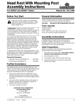
Road Saw Spray Bar Installation
Refer to Figure 5 or Figure 6:
1. Holes will need to drilled in the top of the Road Saw
hood.
a. In the center of the road saw upper panel, (See
Arrow), drill one 3/4" diameter hole in the center of
the top panel.
b. Locate spray bar tube (#9) with nozzle (#2)
projecting through the 3/4" drilled hole, elbow
fitting (#4) and barb fitting (#6) at the back, and
cap (#5) at the front as shown.
c. Locate spray bar mounts (#7) under spray bar
tube (#9) and use as a template. Mark location of
mounting holes to be drilled.
d. Drill four 9/32" diameter mounting holes in the top
panel.
2. Attach spray bar mounts (#7) to the top panel with 1/
4"-20 bolts (#10), narrow flat washers (#14), and
nylock nuts (#13).
3. Align spray bar mounts (#7) with spray bar tube (#9)
and tighten nylock nuts (#13) to the correct torque.
4. Pull latch assemblies (#8) over spray bar tube (#9)
and catch on machine screws (#11).
5. Make sure vinyl tube (#1) is long enough to attach to
barb fitting (#6) with allowance for the Road Saw to
be tilted, raised, and lowered. Cut vinyl tube to a
length that allows for all movements.
6. Attach vinyl tube to barb fitting (#6) with a hose
clamp. See vinyl tube (#1) and hose clamp (#8) in
Figure 1 on page 2.
7. Continue with “Zip Ties” on page 5.
SW3010 Series Road Saws
Figure 5
SW3018 Series Road Saws
Figure 6
72183
B
a
c
k
F
r
o
n
t
72139
B
a
c
k
F
r
o
n
t
Spray Bar Kit Installation
Figure 4
73697
B
a
c
k
F
r
o
n
t

Section 1: Installation
Water Spray Kit For CP30 Series Cold Planers and SW30 Series Road Saws 350-454MK6/17/20
5
Table of Contents
Shut Off Valve Zip tie Locations
Figure 7
Zip Ties
Refer to Figure 7:
1. Add one zip tie (#A) above ball valve (#13) and one
below as shown.
2. Refer to Figure 1 & Figure 2:
Add additional zip ties as needed to secure the vinyl
tube and to keep it from becoming pinched,
stretched, and/or damaged.
73096
A
A
13
8
8
3
3
NOTE: Zip ties (A) are customer supplied.

Section 2: Parts List
Water Spray Kit For CP30 Series Cold Planers and SW30 Series Road Saws 350-454MK 6/17/20
6
Table of Contents
Section 2: Parts List
Water Tank Kit, CP30 #350-378A
1 106-1011 1/2" ID VINYL TUBE . . . . . . . . . . . . . . . . . . . . . . . . . . 240 inches (Cut to length)
2 106-1013 FITTING, 3/4 MP-1/2 BARB ST . . . . . . . . . . . . . . . . . . . . . . . . . . . . . . . . . . . . . .1
3 106-1017 FITTING, BRASS 1/2" MP-1/2"ST . . . . . . . . . . . . . . . . . . . . . . . . . . . . . . . . . . . .2
4 106-1018 PLASTIC 1/2 MP-1/2 BARB ST . . . . . . . . . . . . . . . . . . . . . . . . . . . . . . . . . . . . . .2
5 106-1019 CPLR, MALE 1/2 BODY 3/4 PIPE . . . . . . . . . . . . . . . . . . . . . . . . . . . . . . . . . . . .1
6 106-1020 CPLR, FML 1/2 BODY-3/4 PIPE . . . . . . . . . . . . . . . . . . . . . . . . . . . . . . . . . . . . .1
7 106-1981 40 GAL WATER TANK LOPRO . . . . . . . . . . . . . . . . . . . . . . . . . . . . . . . . . . . . . .1
8 106-2144 HOSE CLAMP. . . . . . . . . . . . . . . . . . . . . . . . . . . . . . . . . . . . . . . . . . . . . . . . . . .6
9 106-2181 3/4" PIPE BLKHD FITTING . . . . . . . . . . . . . . . . . . . . . . . . . . . . . . . . . . . . . . . . .1
10 106-2182 8" LID VENTED W/RING . . . . . . . . . . . . . . . . . . . . . . . . . . . . . . . . . . . . . . . . . . .1
11 106-2200 WLDMNT, TANK SUPPORT . . . . . . . . . . . . . . . . . . . . . . . . . . . . . . . . . . . . . . . .1
12 106-2203 SIDE PLT, TANK SUPPORT NARROW . . . . . . . . . . . . . . . . . . . . . . . . . . . . . . . .2
13 106-2496 1/2" PIPE FEMALE BALL VALVE . . . . . . . . . . . . . . . . . . . . . . . . . . . . . . . . . . . .1
14 106-3948 SIDE PLT, TANK SUPPORT WIDE . . . . . . . . . . . . . . . . . . . . . . . . . . . . . . . . . . .2
15 106-5546 10' RATCHET STRAP . . . . . . . . . . . . . . . . . . . . . . . . . . . . . . . . . . . . . . . . . . . . .2
16 106-6503 31" BUNGEE CORD . . . . . . . . . . . . . . . . . . . . . . . . . . . . . . . . . . . . . . . . . . . . . .2
17 802-258C HHCS 1/2-13X1 GR5 . . . . . . . . . . . . . . . . . . . . . . . . . . . . . . . . . . . . . . . . . . . . .8
18 803-020C NUT HEX 1/2-13 PLT . . . . . . . . . . . . . . . . . . . . . . . . . . . . . . . . . . . . . . . . . . . . .8
19 804-016C WASHER FLAT 1/2 SAE PLT. . . . . . . . . . . . . . . . . . . . . . . . . . . . . . . . . . . . . . .16
Item Part No. Part Description Qty.

Section 2: Parts List
Water Spray Kit For CP30 Series Cold Planers and SW30 Series Road Saws 350-454MK6/17/20
7
Table of Contents
Cold Planer Spray Bar Kit
1 350-379A SPRAY BAR KIT, CP3012LF . . . . . . . . . . . . . . . . . . . . . . . . . . . . . With 3 Nozzles
1 350-380A SPRAY BAR KIT, CP3016LF . . . . . . . . . . . . . . . . . . . . . . . . . . . . . With 3 Nozzles
1 350-381A SPRAY BAR KIT, CP3018 . . . . . . . . . . . . . . . . . . . . . . . . . . . . . . . With 3 Nozzles
1 350-382A SPRAY BAR KIT, CP3024 . . . . . . . . . . . . . . . . . . . . . . . . . . . . . . . With 3 Nozzles
1 350-383A SPRAY BAR KIT, CP3030 . . . . . . . . . . . . . . . . . . . . . . . . . . . . . . . With 4 Nozzles
1 350-384A SPRAY BAR KIT, CP3040 . . . . . . . . . . . . . . . . . . . . . . . . . . . . . . . With 4 Nozzles
1 350-385A SPRAY BAR KIT, CP3048 . . . . . . . . . . . . . . . . . . . . . . . . . . . . . . . With 4 Nozzles
2 106-0925 NOZZLE, WATER KIT (CP & RS) . . . . . . . . . . . . . . . . . . . . . Coincide with Item 8
3 106-0926 NOZZLE SADDLE ASSEMBLY . . . . . . . . . . . . . . . . . . . . . . . Coincide with Item 8
4 106-0966 WATER KIT CLAMP ASSY . . . . . . . . . . . . . . . . . . . . . . . . . . . . . . . . . . . . . . . . . 2
5 106-1000 FITTING, 1/2" PIPE-F ELBOW . . . . . . . . . . . . . . . . . . . . . . . . . . . . . . . . . . . . . . 1
6 106-1016 FITTING, 1/2" PIPE-F CAP . . . . . . . . . . . . . . . . . . . . . . . . . . . . . . . . . . . . . . . . . 1
7 106-1017 FITTING, BRASS 1/2" MP-1/2"ST . . . . . . . . . . . . . . . . . . . . . . . . . . . . . . . . . . . . 1
8 106-5825 SPRAY BAR TUBE CP3012 . . . . . . . . . . . . . . . . . . . . . . . . . . . . . . . . . . . . . . . . 1
8 106-5826 SPRAY BAR TUBE CP3016 . . . . . . . . . . . . . . . . . . . . . . . . . . . . . . . . . . . . . . . . 1
8 106-5827 SPRAY BAR TUBE CP3018 . . . . . . . . . . . . . . . . . . . . . . . . . . . . . . . . . . . . . . . . 1
8 106-5828 SPRAY BAR TUBE CP3024 . . . . . . . . . . . . . . . . . . . . . . . . . . . . . . . . . . . . . . . . 1
8 106-5829 SPRAY BAR TUBE CP3030 . . . . . . . . . . . . . . . . . . . . . . . . . . . . . . . . . . . . . . . . 1
8 106-5830 SPRAY BAR TUBE CP3040 . . . . . . . . . . . . . . . . . . . . . . . . . . . . . . . . . . . . . . . . 1
8 106-5831 SPRAY BAR TUBE CP3048 . . . . . . . . . . . . . . . . . . . . . . . . . . . . . . . . . . . . . . . . 1
9 106-6501 CLAMP SPACER. . . . . . . . . . . . . . . . . . . . . . . . . . . . . . . . . . . . . . . . . . . . . . . . . 4
10 802-274C HHCS 1/4-20X3 GR5 . . . . . . . . . . . . . . . . . . . . . . . . . . . . . . . . . . . . . . . . . . . . . 4
11 803-255C NUT HEX NYLOCK 1/4-20 . . . . . . . . . . . . . . . . . . . . . . . . . . . . . . . . . . . . . . . . . 4
12 804-007C WASHER FLAT 1/4 SAE PLT . . . . . . . . . . . . . . . . . . . . . . . . . . . . . . . . . . . . . . . 8
73059
Item Part No. Part Description Qty.

Section 2: Parts List
Water Spray Kit For CP30 Series Cold Planers and SW30 Series Road Saws 350-454MK 6/17/20
8
Table of Contents
Road Saw Spray Bar Kit
1 350-390A SPRAY BAR KIT, AP-SW30 . . . . . . . . . . . . . . . . . . . . . . . . . . . . . . .With 1 Nozzle
2 106-0925 NOZZLE, WATER KIT . . . . . . . . . . . . . . . . . . . . . . . . . . . . . . . . . . . . . . . . . . . . .1
3 106-0926 NOZZLE SADDLE ASSEMBLY . . . . . . . . . . . . . . . . . . . . . . . . . . . . . . . . . . . . . .1
4 106-1000 FITTING, 1/2" PIPE-F ELBOW . . . . . . . . . . . . . . . . . . . . . . . . . . . . . . . . . . . . . .1
5 106-1016 FITTING, 1/2" PIPE-F CAP . . . . . . . . . . . . . . . . . . . . . . . . . . . . . . . . . . . . . . . . .1
6 106-1017 FITTING, BRASS 1/2" MP-1/2"ST . . . . . . . . . . . . . . . . . . . . . . . . . . . . . . . . . . . .1
7 106-5789 WLDMNT, SPRAY BAR MOUNT . . . . . . . . . . . . . . . . . . . . . . . . . . . . . . . . . . . . .2
8 106-5824 LATCH ASSEMBLY . . . . . . . . . . . . . . . . . . . . . . . . . . . . . . . . . . . . . . . . . . . . . . .2
9 106-6462 SPRAY BAR TUBE . . . . . . . . . . . . . . . . . . . . . . . . . . . . . . . . . . . . . . . . . . . . . . .1
10 802-005C HHCS 1/4-20X1 GR5 . . . . . . . . . . . . . . . . . . . . . . . . . . . . . . . . . . . . . . . . . . . . .4
11 801-135C SRHMS 10-24 X 1 1/4 . . . . . . . . . . . . . . . . . . . . . . . . . . . . . . . . . . . . . . . . . . . . .6
12 803-268C NUT HEX NYLOCK 10-24 PLT . . . . . . . . . . . . . . . . . . . . . . . . . . . . . . . . . . . . . .6
13 803-255C NUT HEX NYLOCK 1/4-20 . . . . . . . . . . . . . . . . . . . . . . . . . . . . . . . . . . . . . . . . .4
14 804-007C WASHER FLAT 1/4 SAE PLT. . . . . . . . . . . . . . . . . . . . . . . . . . . . . . . . . . . . . . . .8
15 804-046C WASHER FLAT #10 SAE PLT . . . . . . . . . . . . . . . . . . . . . . . . . . . . . . . . . . . . . . .6
73697
Item Part No. Part Description Qty.

Section 3: Torque Values Chart
Water Spray Kit For CP30 Series Cold Planers and SW30 Series Road Saws 350-454MK6/17/20
9
Table of Contents
Section 3: Torque Values Chart
Torque Values Chart for Common Bolt Sizes
Bolt Head Identification Bolt Head Identification
Bolt Size
(inches) Grade 2 Grade 5 Grade 8
Bolt Size
(Metric) Class 5.8 Class 8.8 Class 10.9
in-tpi
1
N · m
2
ft-lb
3
N · m ft-lb N · m ft-lb mm x pitch
4
N · m ft-lb N · m ft-lb N · m ft-lb
1/4" - 20 7.4 5.6 11 8 16 12 M 5 X 0.8 4 3 6 5 9 7
1/4" - 28 8.5 6 13 10 18 14 M 6 X 1 7 5 11 8 15 11
5/16" - 18 15 11 24 17 33 25 M 8 X 1.25 17 12 26 19 36 27
5/16" - 24 17 13 26 19 37 27 M 8 X 1 18 13 28 21 39 29
3/8" - 16 27 20 42 31 59 44 M10 X 1.5 33 24 52 39 72 53
3/8" - 24 31 22 47 35 67 49 M10 X 0.75 39 29 61 45 85 62
7/16" - 14 43 32 67 49 95 70 M12 X 1.75 58 42 91 67 125 93
7/16" - 20 49 36 75 55 105 78 M12 X 1.5 60 44 95 70 130 97
1/2" - 13 66 49 105 76 145 105 M12 X 1 90 66 105 77 145 105
1/2" - 20 75 55 115 85 165 120 M14 X 2 92 68 145 105 200 150
9/16" - 12 95 70 150 110 210 155 M14 X 1.5 99 73 155 115 215 160
9/16" - 18 105 79 165 120 235 170 M16 X 2 145 105 225 165 315 230
5/8" - 11 130 97 205 150 285 210 M16 X 1.5 155 115 240 180 335 245
5/8" - 18 150 110 230 170 325 240 M18 X 2.5 195 145 310 230 405 300
3/4" - 10 235 170 360 265 510 375
M18 X 1.5 220 165 350 260 485 355
3/4" - 16 260 190 405 295 570 420 M20 X 2.5 280 205 440 325 610 450
7/8" - 9 225 165 585 430 820 605
M20 X 1.5 310 230 650 480 900 665
7/8" - 14 250 185 640 475 905 670 M24 X 3 480 355 760 560 1050 780
1" - 8 340 250 875 645 1230 910 M24 X 2 525 390 830 610 1150 845
1" - 12 370 275 955 705 1350 995 M30 X 3.5 960 705 1510 1120 2100 1550
1-1/8" - 7 480 355 1080 795 1750 1290 M30 X 2 1060 785 1680 1240 2320 1710
1-1/8" - 12 540 395 1210 890 1960 1440 M36 X 3.5 1730 1270 2650 1950 3660 2700
1-1/4" - 7 680 500 1520 1120 2460 1820 M36 X 2 1880 1380 2960 2190 4100 3220
1-1/4" - 12 750 555 1680 1240 2730 2010
1
in-tpi = nominal thread diameter in inches-threads per inch
1-3/8" - 6 890 655 1990 1470 3230 2380
2
N· m = newton-meters
1-3/8" - 12 1010 745 2270 1670 3680 2710
3
ft-lb= foot pounds
1-1/2" - 6 1180 870 2640 1950 4290 3160
4
mm x pitch = nominal thread diameter in millimeters x thread
pitch
1-1/2" - 12 1330 980 2970 2190 4820 3560
Torque tolerance + 0%, -15% of torquing values. Unless otherwise specified use torque values listed above.
5.8
8.8 10.9

KUBOTA TRACTOR CORPORATION
1000 Kubota Drive, Grapevine, TX 76051
Telephone: (817) 756-1171
Western Division:
Telephone:
1175 S. Guild Ave., Lodi, CA 95240
(209) 334-9910
Midwest Division:
Telephone:
31700 W. 207th ST., Edgerton, KS 66021
(913) 215-5915
Central Division:
Telephone:
14855 FAA Blvd., Fort Worth, TX 76155
(817) 571-0900
Northern Division:
Telephone:
6300 at One Kubota Way, Groveport, OH 43125
(614) 835-1100
Southeast Division:
Telephone:
1025 Northbrook Parkway, Suwanee, GA 30024
(770) 995-8855
/