Tripp Lite B022-U08-IP & B022-U16-IP Owner's manual
- Category
- Rack consoles
- Type
- Owner's manual

1
Owner’s Manual
NetDirector
®
1U Rack-Mount
KVM Switches with IP Access
Models: B022-U08-IP, B022-U16-IP
1111 W. 35th Street, Chicago, IL 60609 USA • www.tripplite.com/support
Copyright © 2019 Tripp Lite. All rights reserved. All trademarks are the property of their respective owners.
WARRANTY REGISTRATION
Register your product today and be
automatically entered to win an ISOBAR
surge protector in our monthly drawing!
www.tripplite.com/warranty

2
1. FCC Information 3
2. User Notice 3
3. Package Contents 3
4. Introduction 3
4.1 Features 3
4.2 System Requirements 4
4.2.1 External Console 4
4.2.2 Computers 4
4.2.3 Remote Console 4
4.2.4 Supported Browsers 4
4.2.5 Custom KVM Cable Kits 4
4.2.6 Operating Systems 4
4.3 Components 5
4.3.1 Front View 5
4.3.2 Rear View 5
5. Installation 6
5.1 General Safety Instructions 6
5.2 Rack Mounting Instructions 7
5.3 Grounding 7
5.4 Installation 7
5.5 Network Setup-IP Address Configuration 8
5.5.1 Local Console 8
5.5.2 IP Installer 8
5.5.3 Browser/Non-Browser Client 9
5.5.4 Changing the Super Administrator Login 10
6. KVM Operation 11
6.1 Sharing USB Peripheral Devices 11
6.2 Powering Off and Restarting 11
6.3 Local Console Login 11
6.4 Local Console Port Access 12
6.4.1 Local Console OSD Invocation Sequence 12
6.4.2 Local Console OSD Navigation 12
6.4.3 Local Console OSD Main Screen Headings 12
6.4.4 Local Console OSD F1 GOTO Function 12
6.4.5 Local Console OSD F5 Skip Function 12
6.4.6 Local Console OSD F6 Broadcast Mode (BRC) 13
6.4.7 Local Console OSD F7 Auto Scan Function 13
6.4.8 Local Console OSD F8 Logout Function 13
6.4.9 Local Console Pushbuttons 13
6.4.10 Local Console Hotkey Commands 13
6.5 Logging Into the KVM over IP 15
6.5.1 Browser Login 15
6.5.2 AP Windows Client Login 16
6.5.3 AP Java Client Login 17
6.6 Remote Session Operation 18
6.6.1 Control Panel 18
6.6.2 The OSD Toolbar 27
6.6.3 Auto Scanning 29
7. Administration 30
7.1 Local Console OSD 31
7.1.1 Local Console OSD F2 LIST Function 31
7.1.2 Local Console OSD F3 Settings (SET) Page 31
7.1.3 Local Console OSD F4 Administration (ADM) 32
Page
7.1.4 Local Console Firmware Upgrade 34
7.2 OSD Operation 35
7.2.1 OSD Main Page 35
7.2.2 OSD Tab Bar 36
7.2.3 Port Access 36
7.2.4 Connections 37
7.2.5 Favorites 40
7.2.6 User Preferences 41
7.2.7 Sessions 41
7.2.8 Access 42
7.2.9 Port Configuration 43
7.2.10 User Management 44
7.2.11 Device Management 47
7.2.12 Device Information 47
7.2.13 Operating Mode 47
7.2.14 Network 48
7.2.15 Advanced Network Management Settings 49
7.2.16 Security 55
7.2.17 Date/Time 57
7.2.18 Log 60
7.2.19 Maintenance 60
7.2.20 Download 61
7.3 Log Server 62
8. Specifications 64
8.1 OSD Default Settings 64
8.2 Keyboard Emulation 66
9. Warranty & Product Registration 67
Table of Contents

3
1. FCC Information
2. User Notice
3. Package Contents
This is an FCC Class A product. In a domestic environment this product may cause radio interference in which case the user may be required
to take adequate measures.
This equipment has been tested and found to comply with the limits for a Class A digital device, pursuant to Part 15 of the FCC Rules.
These limits are designed to provide reasonable protection against harmful interference when the equipment is operated in a commercial
environment. This equipment generates, uses and can radiate radio frequency energy and, if not installed and used in accordance with the
instruction manual, may cause harmful interference to radio communications. Operation of this equipment in a residential area is likely to
cause harmful interference in which case the user will be required to correct the interference at his own expense.
All information, documentation and specifications contained in this manual are subject to change without prior notification by the
manufacturer. The manufacturer makes no representations or warranties, either expressed or implied, with respect to the contents hereof
and specifically disclaims any warranties as to merchantability or fitness for any particular purpose. Any of the manufacturer’s software
described in this manual is sold or licensed “as is.” Should the programs prove defective following their purchase, the buyer (and not the
manufacturer, its distributor or its dealer), assumes the entire cost of all necessary servicing, repair and any incidental or consequential
damages resulting from any defect in the software.
The manufacturer of this system is not responsible for any radio and/or TV interference caused by unauthorized modifications to this device.
It is the responsibility of the user to correct such interference.
The manufacturer is not responsible for any damage incurred in the operation of this system if the correct operational voltage setting was not
selected prior to operation. PLEASE VERIFY THAT THE VOLTAGE SETTING IS CORRECT BEFORE USE.
This package consists of:
• B022-U08-IP or B022-U16-IP
KVM Switch
• 6 ft. USB/PS2 Combo KVM
Cable Kits (x2)
• USB/PS2 Combo Console Cable Kit
• RJ11 to DB9 Firmware Upgrade Cable
• Rack-Mount Hardware
• External Power Supply
• Rubber Feet
• CD with Owner’s Manual, Quick Start
Guide and Device Files
• Quick Start Guide
4. Introduction
4.1 Features
• 1U Rack-Mount KVM Switch with built-in IP access.
• Connect either USB or PS/2 computers using P778-Series USB/PS2 Combo KVM Cable Kits – no need for separate cable kits.
• Control up to 8 (B022-U08-IP) or 16 (B022-U16-IP) computers on a single KVM switch.
• Remotely access computers via LAN, WAN or Internet via the Windows™ or Java browser clients.
• AP Windows and Java clients allow the KVM to be remotely accessed via the network without going through a browser.
• External USB 1.1 port allows USB peripheral devices to be shared amongst connected computers.
• Grayscale feature allows you to view remote sessions in black and white, reducing the amount of data traveling over the network and
improving keyboard/mouse response time over IP.
• Web management interface, OSD and toolbars provide convenient, user-friendly operation.
• 3-level security (Admin, User and Select) – up to 64 accounts can be created.
• Panel Array Mode – remotely monitor multiple ports at the same time.
• Message board feature allows users who are logged in at the same time to communicate with each other and manage port access.
• CD includes a Windows-based log server that records events on the installation and writes them to a searchable database.
• Supports RADIUS and LDAP/S authentication.
• Flash firmware upgradable via network and included firmware upgrade cable.
• Supports both IPv4 and IPv6.
• Supports Link Local IPv6 Address and IPv6 Stateless Auto configuration protocol.
• Web Management Interface, Remote OSD and Local OSD can be displayed in English, Spanish, French, German and Japanese.
• Advanced encryption technologies: 128-bit SSL, 128-bit RC4, 1024-bit RSA, 56-bit DES, 256-bit AES, 168-bit 3DES.
• Video resolutions up to 1920 x 1080, DDC2B are supported at the local console. Video resolutions up to 1920 x 1080 @ 60Hz,
24-bit color depth are supported at the remote console.
Check to make sure that all of the components are present and in good order. If anything is missing, or was damaged in shipping, contact
your dealer.
Read this manual thoroughly and follow the installation and operation procedures carefully to prevent any damage to the switch or to any
other devices in the installation.

4
4.2.1 External Console
• A VGA, SVGA or MultiSync monitor capable of displaying the
highest resolution provided by any computer in the installation.
• PS/2 or USB keyboard and mouse.
4.2.2 Computers
The following equipment must be installed on each computer:
• A VGA, SVGA or MultiSync video graphics card with an HD15
port.
Either:
• PS/2 mouse and keyboard ports (6-pin Mini-DIN).
• USB port.
4.2.3 Remote Console
• For best results, computers that remotely access the KVM switch
should have at least a Pentium III 1 GHz processor.
• Users who want to access the KVM switch with the Windows
client must have DirectX 8.0 or higher installed. DirectX
is available for free download from Microsoft’s Website:
http://www.microsoft.com/downloads.
• Users who want to access the KVM switch with the Java
client must have Sun’s Java 6 (update 3 or higher) runtime
environment installed. Java is available for free download from
the Sun Java Website: http://java.com.
• For best results, a network transfer speed of at least 128 Kbps is
recommended.
• Browsers must support 128-bit data encryption.
• To run the Log Server, you must have the Microsoft Jet 0LED8
4.0 (or higher) driver installed.
4. Introduction
(
continued
)
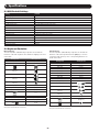
4.2.4 Supported Browsers
Browser Versions Supported
Internet Explorer 6 and higher
Firefox 1.5 and higher
Mozilla 1.7 and higher
Safari 4.0 and higher
Opera 9.0 and higher
Netscape 8.1 and higher
4.2.5 Custom KVM Cable Kits
The KVM switch uses custom P778-Series USB/PS2 Combo KVM Cable Kits, which can be used to connect to a computer with either USB
or PS/2 connectors. One cable kit is required for each connected computer.
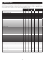
4.2.6 Operating Systems
Supported operating systems are shown in the table, below:
Operating System Versions Supported
Windows 2000 and higher
Linux RedHat 7.1 and higher
Linux Fedora Core 5 and higher
Linux SuSE 9.0 and higher
Linux Mandriva (Mandrake) 9.0 and higher
UNIX AIX 3.51 and higher
Operating System Versions Supported
UNIX Free BSD 3.51 and higher
UNIX Sun Solaris 8 and higher
Novell Netware 5.0 and higher
Mac OS 9 and higher
DOS 6.2 and higher
4.2 System Requirements

5
4. Introduction
(
continued
)
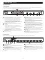
1
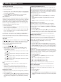
Port Selection Pushbuttons: These buttons toggle between
the computers attached to the corresponding KVM ports.
• Simultaneously pressing and holding buttons 1 and 2 for
three seconds will perform a keyboard / mouse reset.
• Simultaneously pressing and holding buttons 7 and 8
(for B022-U08-IP) or 15 and 16 (for B022-U16-IP) for three
seconds will initiate an Auto Scan.
2
Port LEDs: The Port LEDs are built into the Port Selection
Pushbuttons.
• An Online LED on the left side of the pushbutton will
illuminate Orange to indicate that a powered-on computer is
connected to the corresponding port.
• A Selected LED on the right side of the pushbutton will
illuminate Green to indicate that the corresponding port has
the focus of the KVM.
3
Reset Button: Press this recessed button with a thin object to
perform a system reset.
4
USB Peripheral Port: A USB 1.1 port is provided for the
sharing of USB peripherals among connected computers (e.g.
flash drive, CD-ROM drive, etc.).
Note: USB peripherals can only be shared among computers that are
connected to the KVM switch via the USB connectors on the P778-
Series USB/PS2 Combo KVM Cable Kit.
5
Firmware Upgrade Switch: During a firmware upgrade, as
well as normal operation, this switch should be in the NORMAL
position. If a firmware upgrade does not perform successfully,
this switch is flipped to the RECOVER position during the
firmware upgrade recovery process (See the Firmware Upgrade
section of this manual for details).
6
Firmware Upgrade Port: The RJ11 connector on the included
firmware upgrade cable connects to the KVM switch here.
7
Power LED: The Power LED illuminates blue to indicate the unit
is receiving power.
8
Station ID LED: The Station ID LED will display the number of
the station that currently has the console’s focus.
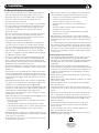
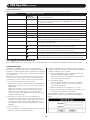
1
Daisy-chain-Out Port
2
KVM Ports: The custom wired KVM cable kits that connect to
the computers plug in here.
3
Grounding Terminal: The wire (user provided) used to ground
the unit connects to the KVM here.
4
Cable Tie Slot: A cable tie can be routed through this slot in
order to tie the connected cables together for organizational
purposes.
5
Power Jack: The included power supply connects to the KVM
here.
6
LAN Port: The cable that connects the KVM switch to a LAN,
WAN or Internet plugs in here.
7
Console Port: The included USB/PS2 Combo Console Cable Kit
connects to the KVM switch here, allowing you to attach a VGA
monitor and USB or PS/2 keyboard/mouse.
4.3 Components
4.3.1 Front View
Note: The diagram below shows the B022-U08-IP. The B022-U16-IP will be the same, except for the number of KVM ports and KVM pushbuttons. Also,
an Auto Scan can be initiated on the B022-U16-IP by pressing pushbuttons 15 and 16 instead of 7 and 8.
4.3.2 Rear View
Note: The diagram below shows the B022-U08-IP. The B022-U16-IP will be the same, except for the number of KVM ports.
2
23 4 5 6 7
3
1
4 5 6 7 8
1

6
5. Installation
• Read all of these instructions. Save them for future reference.
• Follow all warnings and instructions marked on the device.
• Do not place the device on any unstable surface (cart, stand,
table, etc.). If the device falls, serious damage will result.
• Do not use the device near water.
• Do not place the device near, or over, radiators or heat registers.
• The device cabinet is provided with slots and openings to allow
for adequate ventilation. To ensure reliable operation, and to
protect against overheating, these openings must never be
blocked or covered.
• The device should never be placed on a soft surface (bed, sofa,
rug, etc.) as this will block its ventilation openings. Likewise,
the device should not be placed in a built-in enclosure unless
adequate ventilation has been provided.
• Never spill liquid of any kind on the device.
• Unplug the device from the wall outlet before cleaning. Do not
use liquid or aerosol cleaners. Use a damp cloth for cleaning.
• The device should be operated from the type of power source
indicated on the marking label. If you are not sure of the type of
power available, consult your dealer or local power company.
• This device is designed for IT power distribution systems with up
to 230V phase-to-phase voltage.
• The device is equipped with a 3-wire grounding type plug. This
is a safety feature. If you are unable to insert the plug into the
outlet, contact your electrician to replace your obsolete outlet.
Do not attempt to defeat the purpose of the grounding-type plug.
Always follow your local/national wiring codes.
• Do not allow anything to rest on the power cord or cables. Route
the power cord and cables so that they cannot be stepped on or
tripped over.
• If an extension cord is used with this device make sure that the
total of the ampere ratings of all products used on this cord does
not exceed the extension cord ampere rating. Make sure that the
total of all products plugged into the wall outlet does not exceed
15 amperes.
• Consideration should be given to the connection of equipment to
the supply circuit, and what effect overloading the supply circuit
might have on overcurrent protection and supply wiring.
• To help protect your system from sudden, transient increases and
decreases in electrical power, use a Tripp Lite Surge Suppressor,
Line Conditioner or Uninterruptible Power Supply (UPS).
• Position system cables and power cables carefully; be sure that
nothing rests on any cables.
• When connecting or disconnecting power to hot-pluggable power
supplies, observe the following guidelines:
• Install the power supply before connecting the power cable to
the power supply.
• Unplug the power cable before removing the power supply.
• If the system has multiple sources of power, disconnect power
from the system by unplugging all power cables from the
power supplies.
• Never push objects of any kind into or through cabinet slots. They
may touch dangerous voltage points or short out parts resulting in
a risk of fire or electrical shock.
• Do not attempt to service the device yourself. Refer all servicing
to qualified service personnel.
• If the following conditions occur, unplug the device from the wall
outlet and bring it to qualified service personnel for repair:
• The power cord or plug has become damaged or frayed.
• Liquid has been spilled into the device.
• The device has been exposed to rain or water.
• The device has been dropped, or the cabinet has been
damaged.
• The device exhibits a distinct change in performance,
indicating a need for service.
• The device does not operate normally when the operating
instructions are followed.
• Only adjust those controls that are covered in the operating
instructions. Improper adjustment of other controls may result in
damage that will require extensive work by a qualified technician
to repair.
• Use of this equipment in life support applications where failure of
this equipment can reasonably be expected to cause the failure
of the life support equipment or to significantly affect its safety or
effectiveness is not recommended. Do not use this equipment in
the presence of a flammable anesthetic mixture with air, oxygen
or nitrous oxide.
Rack Mounting Safety Instructions
• The ambient operating temperature in the rack may be an issue
and is dependent upon the rack load and ventilation. When
installing in a closed or multi-unit rack assembly, make sure that
the temperature will not exceed the maximum rated ambient
temperature.
• Before working on the rack, make sure that the stabilizers are
secured to the rack, extended to the floor, and that the full weight
of the rack rests on the floor. Install front and side stabilizers on
a single rack or front stabilizers for joined multiple racks before
working on the rack.
• Always load the rack from the bottom up, and load the heaviest
item in the rack first.
• Always load the rack so that a hazardous condition is not created
due to uneven loading.
• Make sure that the rack is level and stable before extending a
device from the rack.
• Use caution when pressing the device rail release latches and
sliding a device into or out of a rack; the slide rails can pinch your
fingers.
• After a device is inserted into the rack, carefully extend the rail
into a locking position, and then slide the device into the rack.
• Do not overload the AC supply branch circuit that provides power
to the rack. The total rack load should not exceed 80% of the
branch circuit rating.
• Ensure that proper airflow is provided to devices in the rack.
• Do not step on or stand on any device when servicing other
devices in a rack.
• Do not connect the RJ11 connector marked “Upgrade” to a
public telecommunication network.
• Caution! Slide/Rail (LCD KVM) mounted equipment is not to be
used as a shelf or a work space.
5.1 General Safety Instructions
CAUTION!
Slide/rail-mounted
equipment is not to be
used as a shelf
or a workspace.

3
2
6 5
4
7
5. Installation
(
continued
)
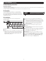
To prevent damage to your installation, it is important that all
devices are properly grounded. Using a user-supplied grounding
wire, ground the KVM switch by connecting one end of the wire to
the grounding terminal on the unit, and the other end of the wire to
a suitably grounded object.
To install your KVM switch, refer to the following steps and
installation diagram.
1
Power OFF all computers that are being connected to the KVM
switch.
2
Add an external console to the KVM by connecting the included
USB/PS2 console cable kit to the console port on the back
of the unit, and then connecting an external monitor (HD15),
keyboard (USB or PS/2) and mouse (USB or PS/2) to the
connectors on the cable kit.
3
Connect a P778-Series USB/PS2 Combo KVM Cable Kit
between an available KVM port on the back of the unit and a
computer/server. P778-Series Cable Kits allow you to connect
to a computer with either USB or PS/2* keyboard/mouse ports,
without the need for separate cables. Note: The distance
between the KVM and the connected computer must not
exceed 33 ft. (10 m).
4
Repeat step 3 for each additional computer you wish to
connect.
5
Connect the LAN port on the back of the unit to the network
using Cat5e/6 cabling.
6
Connect the included external power supply to the KVM switch,
and then plug it into a Tripp Lite Surge Suppressor, PDU or
Uninterruptible Power Supply (UPS).
7
After the KVM switch powers up, power ON the connected
computers.
*When connecting to computers using the PS/2 connectors of a P778-
Series Cable Kit, the Mouse Sync Mode setting must be set to Manual
in order to access the computer over IP. If Mouse Sync Mode is set to
Automatic, you will not have mouse functionality when accessing that
computer over IP. This setting is set to Manual by default.
5.2 Rack Mounting Instructions
Standard Rack Mounting
1. Depending on whether you want to mount the KVM switch to the front or back of the rack, attach the included rack-mount brackets to the
front or rear sides of the KVM switch.
2. Using user-supplied screws, mount the rack-mount brackets of the KVM switch to the rack.
5.3 Grounding
5.4 Installation

8
Note: The local console OSD only allows you to configure IPv4 network
settings. For IPv6, access the Web Management Interface or Remote
Session OSD.
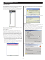
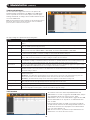
1. When accessing the KVM switch for the first time, a prompt
will appear asking for a Username and Password. The default
Username is administrator, and the default Password is
password. For security purposes, it is strongly recommended
that you change the username and password on this account
to something unique. When you have entered your username
and password, the OSD will appear with the following page
displayed.
2. Press the [F4] key to bring up the OSD Admin page.
3. In the OSD Admin page, highlight SET IP ADDRESS and press the [Enter] key.
4. DHCP – The first field allows you to enable or disable DHCP. When enabled, the KVM is assigned an IP address by the DHCP server. This
setting is enabled by default. To disable the DHCP setting and set up a fixed IP address, press the [Spacebar] key. Once the DHCP is
disabled, you will be allowed to edit the remaining fields in the SET IP ADDRESS screen.
5. In the remaining fields, enter in the IP address, subnet mask and default gateway you want to assign to the KVM switch.
6. Press the [Esc] key to exit the SET IP ADDRESS screen, and to pull up a prompt asking if you wish to save the settings you just entered.
If you do not wish to save the settings, press the [N] key. If you do wish to save the settings, press the [Y] key. Upon pressing the [Y] key,
the settings will be saved and the KVM will be reset.
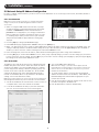
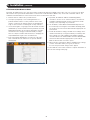
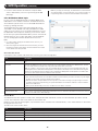
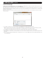
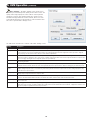
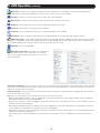
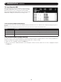
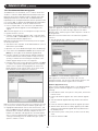
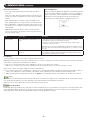
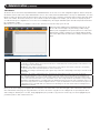
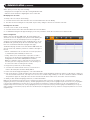
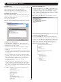
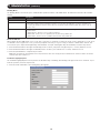
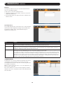
5.5.2 IP Installer
The CD that comes with the product includes a Windows-based IP
Installer utility that can be used to obtain and edit the IP address
assigned to the KVM. To use the IP Installer utility, the computer
you are using must be running a Windows operating system, and
must be on the same network as the KVM. Also, the IP Installer
setting in the Network page of the Web Management Interface
must be set to Enabled, which it is by default (see the Network
settings section in this manual for details).
Note: The IP Installer settings can only be accessed via the browser-based
Web Management Interface. They are not accessible in the Remote OSD.
1. Save the IP Installer.exe file from the CD to a desired location on
a computer that is on the same network as the KVM.
2. Locate the IP Installer.exe file that you just saved and double-
click on it. A screen similar to the one below will appear:
3. Select your KVM from the Device List.
Note: If the list is empty, or your device doesn’t appear, click the
Enumerate button to refresh the Device List. If there is more than one
device in the list, use the MAC address on the bottom of your unit to
determine the desired device.
4. To assign a fixed IP address, check the Use the following IP
address checkbox and fill in the IP Address, Subnet Mask, and
Default Gateway fields with information appropriate for your
network (IPv4 or IPv6).
5. Click the Set IP button to apply the changes to the unit. The new
IP address will appear in the Device List.
6. Click the Exit button to exit the IP Installer utility.
5. Installation
(
continued
)
5.5 Network Setup-IP Address Configuration
In order to configure a fixed IP address, you will need to access the KVM switch in one of four ways; Local Console, IP Installer, Browser or
Non-Browser Clients.
5.5.1 Local Console

9
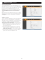
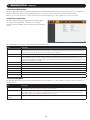
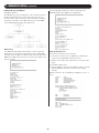
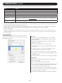
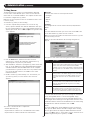
5.5.3 Browser/Non-Browser Client
By default, the KVM switch is set to have an IP address assigned automatically via DHCP server. If this is the case, you will need to obtain
the IP address from your network administrator. If connected to a network without a DHCP server, it boots with a default IP address. The
default IPv4 and IPv6 addresses can be found on the sticker on the bottom of the unit.
1. Enter the unit’s IP address into your web browser.
2. You may be prompted by a screen stating that there is a
problem with this website’s security certificate. Click on the
option to continue to the website anyway. (See Web Browser
Login section for details on installing the security certificate)
3. You will be brought to a login page. Enter the default Username
(administrator), and the default Password (password). The Web
Management Interface will open upon entering the Username
and Password. It is strongly recommended that you change
these to a unique Username and Password (see Changing the
Super Administrator Login section for instructions).
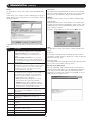
4. Click on the Device Managment icon at the top of the page,
then click Network in the subsections to open the Network
settings page.
5. By default, the Obtain IP address automatically [DHCP]
checkbox is checked. To set a fixed IP address, check the Set
IP address manually [Fixed IP] check box in the IPv4 or IPv6
settings section, depending on your network.
6. The IP Address, Subnet Mask and Default Gateway fields will
be activated upon checking the Set IP address manually [Fixed
IP] checkbox. Fill in these fields with information appropriate for
your network.
7. As with the IP Address settings, the DNS Server settings can be
obtained automatically or assigned manually. To manually enter
these settings, check the Set DNS server address manually
checkbox and fill in the Preferred DNS server and Alternate DNS
server fields with information appropriate for your network.
Note: The Alternate DNS server field is optional.
8. When you have entered the IP Address and DNS Server settings,
click the Save button. When you log out, the unit will
be reset and your network changes will be applied.
See the Network section in this manual for complete information on
the rest of the settings in this page.
5. Installation
(
continued
)

10
5. Installation
(
continued
)
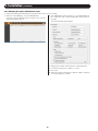
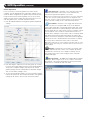
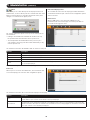
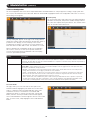
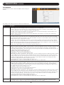
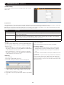
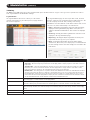
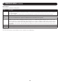
5.5.4 Changing the Super Administrator Login
To change the default Super Administrator Username and Password, do the following:
1. At the top of the OSD page, click User Management.
Since this is the first time the page is being accessed, only the
Super Administrator appears:
2. Click Administrator in the left panel; or, select Administrator in
the central panel and click the Modify button at the bottom of
the page.
The User Information page appears:
3. Change the Username and Password to something unique.
4. Re-enter the password to confirm it is correct.
5. Click Save.
6. When the dialog box informing you that the change completed
successfully appears, click OK.

11
6. KVM Operation
Computers connected to the KVM can be accessed via the local console or over IP. This chapter discusses the basic operation of the KVM
switch, both locally and remotely.
6.1 Sharing USB Peripheral Devices
The USB 1.1 port on the front panel of the KVM switch can be used to share USB peripherals between connected computers. Simply
connect a USB device to this port, and any connected computer you switch to will have access to the device. The USB peripheral sharing
functionality works the same whether you are accessing the connected computers via the local console or over IP.
Note: The following limitations apply to the USB peripheral port:
1. This port serves as a 1-port USB 1.1 hub; USB 2.0 devices can be connected but will not function at USB 2.0 speeds.
2. USB peripherals can only be shared among computers that are connected to the KVM switch via the USB connectors on the P778-Series USB/PS2
Combo KVM Cable Kit.
3. USB peripherals can only be shared among computers that are connected to the KVM switch that the USB peripheral is plugged into. If a USB peripheral
is plugged into the USB 1.1 port of the third KVM switch in a daisy-chain installation, only computers connected to that KVM can access the USB
peripheral; computers connected to any other KVM in the installation will not be able to access the USB peripheral.
4. When accessing a USB peripheral on a connected computer, it is recommended that you properly eject the device before switching to another computer.
When switching computers, the device is automatically disconnected from the previous computer and connected to the next, as if it was manually
unplugged from a USB port on one computer and then plugged into the USB port of another computer.
6.2 Powering Off and Restarting
If it becomes necessary to power off the KVM switch, follow this procedure:
1. Shut down all computers connected to the KVM switch. If you are powering off multiple computers in a daisy-chain installation, shut
down all computers connected to each KVM switch you are powering off.
Note: It is necessary to unplug any computers that have the Keyboard Power On function. If left on, the KVM switch will continue to receive power via
these computers.
2. Starting with the first KVM in the installation, unplug the KVM switch from its power source. Power OFF and unplug each additional KVM
switch in succession.
3. Wait 10 seconds and then plug the KVM switch, starting with the first station, back into its power source.
4. Once the first station KVM switch has ascertained its position in the daisy-chain, power ON and plug in the next KVM switch in the
installation. Follow this procedure for each additional KVM switch in the installation.
5. Once all KVM switches in the installation have been powered back ON, turn on the power to all connected computers.
6.3 Local Console Login
When accessing the console KVM switch for the first time, a prompt
will appear asking for a username and password. The default
username is administrator, and the default password is password.
For security purposes, it is strongly recommended that you change
the username and password on this account to something unique.
Once the KVM has been set up and user accounts have been
created, the login prompt will only appear when a user logs out of
the KVM. When you have entered your username and password,
the OSD will appear with the following page displayed.
Notes:
1. The screenshot depicts the Administrator’s Main Screen. The User Main Screen does not have the F4 and F6 functions, since they can’t be accessed by
ordinary Users and are reserved for the Administrator.
2. OSD always starts in List view, with the highlight bar at the same position it was when the OSD was last closed.
3. Only the ports that have been set accessible by the Administrator for the currently logged in User are visible.
4. If the port list is collapsed into stations, simply click on the plus sign next to the desired station number, or highlight the desired station number and hit
the [Enter] key.

12
6.4 Local Console Port Access
Once logged into the KVM, you can access connected computers via the local console using the Local Console OSD, Local Console
Pushbuttons or Hotkey Commands. The following sections describe all of the ways in which you can access connected computers via the
local console.
6.4.1 Local Console OSD Invocation Sequence
Once logged into the KVM switch and accessing a connected computer, you will need to use one of two sequences to re-open the OSD Main
Menu; [Scroll Lock, Scroll Lock] or [Ctrl, Ctrl]. The default OSD invocation sequence is [Scroll Lock, Scroll Lock].
6.4.2 Local Console OSD Navigation
When in the Local Console OSD, you can use your keyboard and mouse to access its features.
• To close out of the Local Console OSD, click the [X] at the upper right corner of the OSD or press the [Esc] key.
• To logout, press the [F8] key, click the F8 at the top of the OSD, or click the zZz symbol in the upper right hand corner of the OSD.
• To move through the OSD list one line at a time, click the up and down triangle symbols ( , ) or use the [ ] and [ ] keyboard keys. If
there are more entries than appear on the screen, the screen will scroll.
• To move up or down one screen at a time, click the Up and Down Arrow symbols (
,
), or use the [Pg Up] and [Pg Dn] keyboard keys. If
there are more entries than appear on the screen, the screen will scroll.
• To activate a port, double-click it, or highlight it and press the [Enter] key. Once a port is accessed, the OSD will close and the screen of
the computer connected to the port will be displayed.
6.4.3 Local Console OSD Main Screen Headings
SN The Station Number of each KVM in the installation will be displayed in this column. The Station Number of each KVM switch will be displayed as
an expandable folder, which can be expanded to show all of the KVM ports in the corresponding station, or collapsed to hide them.
PN The port numbers of each KVM in the installation are displayed in this column. If the individual stations are collapsed, their port numbers will not
be displayed.
QV An arrow in this column indicates that the corresponding port is selected for Quick View scanning.
A sun symbol in this column indicates that a computer is both connected to the corresponding port and powered ON.
NAME If a port has been given a name, its name appears in this column.
6.4.4 Local Console OSD F1 GOTO Function
Click F1 at the top of the OSD or press the [F1] key to activate the GOTO function. GOTO allows you to search the ports on the installation
by keying in a Name or Port ID. As you type in a Name or Port ID, the OSD list will automatically display all ports in the installation that
match your search terms. To access a port from the list, simply double-click on it or highlight it and press the [Enter] key. To exit GOTO
mode and return to the OSD main page, press the [Esc] key.
• To search by Name, type [1] into the field that appears when the GOTO function is activated; a Name field will appear. Type in a name to
display all accessible ports in the installation that match your entry.
• To search by Port ID, type [2] into the field that appears when the GOTO function is activated; a Port ID field will appear. Type in a port ID
to display all accessible ports in the installation that match your entry.
6.4.5 Local Console OSD F5 Skip Function
Skip Mode allows connected computers to be accessed using the [ ], [ ], [ ] and [ ] keys on the keyboard. To invoke Skip Mode via
the local console OSD, click F5 at the top of the OSD or press the [F5] key. When invoked, the KVM displays the screen of the last selected
port, with a left/right triangle symbol next to the port’s port ID to signify it is being accessed in Skip Mode. The ports accessed in Skip Mode
are determined by the Scan Select setting in the F3 Set page of the local console OSD. During Skip Mode, normal keyboard and mouse
functionality is suspended. Keyboard functionality is limited to those keys mentioned in the table below. Mouse functionality is suspended
altogether.
Key Description
[ ]
Skips from the currently selected port to the next accessible port prior to it.
[ ]
Skips from the currently selected port to the next accessible port after it.
[ ]
Skips from the currently selected port to the last accessible port on the previous station.
[ ]
Skips from the currently selected port to the first accessible port on the next station.
[Esc] Exits Skip Mode at the currently selected port.
[Spacebar] Exits Skip Mode at the currently selected port.
6. KVM Operation
(
continued
)

13
6.4.6 Local Console OSD F6 Broadcast Mode (BRC)
Broadcast Mode is an Administrator-ONLY function. Clicking the F6 at the top of the OSD or pressing the [F6] key invokes Broadcast Mode.
When this function is in effect, commands sent from the console are broadcast to all available computers on the installation. This function
is particularly useful for operations that need to be performed on multiple computers, such as performing a system-wide shutdown, installing
or upgrading software, etc. Broadcast Mode works in conjunction with the F2 LIST function. The F2 LIST function lets you select which ports
will be displayed on the OSD main screen. When a command is broadcast, it is done only to the ports currently displayed on the OSD main
screen.
• A speaker symbol appears before the Port ID Display to indicate Broadcast Mode is in effect.
• The mouse will not function while Broadcast Mode is in effect. You must exit Broadcast Mode in order to regain control of the mouse.
• To exit Broadcast Mode, invoke the OSD (with the OSD hotkey), and then click F6 at the top of the OSD or press the [F6] key.
6.4.7 Local Console OSD F7 Auto Scan Function
Auto Scan Mode allows connected computers to be accessed automatically at set time intervals. To invoke Auto Scan Mode via the local
console OSD, click F7 at the top of the OSD or press the [F7] key. When invoked, the KVM begins scanning according to the Scan Select
and Scan Duration settings in the F3 Set page of the local console OSD. During an auto scan, normal keyboard and mouse functionality
is suspended. Keyboard functionality is limited to the [Spacebar] key (exits auto scan at the currently selected port), [Esc] key (exits auto
scan at the currently selected port) and the [P] key (pauses auto scan at the currently selected port). Mouse functionality is suspended
altogether.
6.4.8 Local Console OSD F8 Logout Function
To logout of the KVM switch, click on the F8 at the top of the page or press the [F8] key. You will be prompted to confirm that you wish to
logout. Press the [Y] key if yes, or the [N] key if no. When logged out, the username and password screen will appear, requiring a username
and password to be entered to access the KVM.
6.4.9 Local Console Pushbuttons
In addition to using the local console OSD to access connected computers, you can access them using the KVM’s pushbuttons. The KVM
switch front panel includes pushbuttons for its ports only. Press a pushbutton to bring the KVM’s focus to the corresponding port.
6.4.10 Local Console Hotkey Commands
When accessing a connected computer via the local console, you
can use hotkey commands to operate the KVM switch instead
of going back into the OSD. This chapter discusses the available
hotkeys and their functions. Below is a list of the various hotkeys,
broken up into those for port control and those that perform other
functions.
Port Control Hotkeys
• Selecting the active port
• Auto Scan Mode port switching
• Skip Mode port switching
Other Hotkeys
• Computer keyboard and mouse reset
• Setting the Beeper
• Setting the Mode Invocation Sequence Hotkey
• Setting the OSD Hotkey
• Setting the Port Operating System
• Restoring the OSD default values
Invoking the Hotkey Mode
All hotkey operations begin by invoking Hotkey Mode. In order for
Hotkey Mode to work, it must be activated in the KVM’s OSD. By
default, Hotkey Mode is enabled. There are two sequences that can
be used to invoke Hotkey Mode, both of which are explained below.
You can toggle between these two sequences using the OSD. The
[Num Lock] and [-] Minus keys are the default invocation keys.
Num Lock and Minus (-) keys
1. Press and hold down the [Num Lock] key.
2. While the [Num Lock] key is held down, press and release the
[-] Minus key.
3. After releasing the [-] Minus key, release the [Num Lock] key.
Control and F12 keys
1. Press and hold down the [Ctrl] key.
2. While the [Ctrl] key is held down, press and release the [F12]
key.
3. After releasing the [F12] key, release the [Ctrl] key.
When Hotkey Mode has been invoked:
• The monitor goes blank and the hotkey command line is
displayed. This is where you will enter in the hotkey commands
described in this chapter.
• The [Caps Lock] and [Scroll Lock] keyboard LEDs will blink in
succession.
• Ordinary keystrokes will be suspended until Hotkey Mode is
exited. Hotkey Mode is exited once a hotkey command is
performed, or by pressing the [Esc] or [Spacebar] keys.
Port ID Numbering
• Each CPU port in an installation is assigned a unique Port ID. The
Port ID is made up of two parts, a Station Number and a Port
Number.
• The Station Number is a two-digit number that identifies the
switch’s position in the daisy chain installation. This corresponds
to the number displayed on the Station ID LED.
• The Port Number is a two-digit number which identifies the port
number of the KVM switch that the computer is connected to.
• The Station Number precedes the Port Number.
• Station and Port numbers are always 2 digits, so 1 - 9 becomes
01 - 09. For example, a computer attached to Port 7 of Station
15 has a Port ID of 15-07.
6. KVM Operation
(
continued
)

14
Selecting the Active Port
You can directly access a port by doing the following:
1. Invoke Hotkey Mode.
2. Enter the Port ID. The Port ID numbers appear on the command
line as they are entered. To correct a mistake, use [Backspace]
to erase the wrong number.
3. Press the [Enter] key; the KVM switches to the designated
computer and you automatically exit Hotkey Mode.
Auto Scan Mode
When invoked, Auto Scan Mode monitors the connected computers
automatically at regular intervals so that you don’t have to manually
switch between them. When in Auto Scan Mode, the KVM switch
monitors the connected computers per the Scan Select and Scan
Duration settings in the F3 Set page of the local console OSD. To
invoke Auto Scan Mode, follow these steps:
1. Invoke Hotkey Mode.
2. Key in [A] and hit the [Enter] key. You automatically exit Hotkey
Mode and enter Auto Scan Mode.
3. Auto Scan Mode can be paused at any time by pressing the [P]
key or left-clicking the mouse. To resume scanning, press any
key or left-click the mouse.
4. To exit Auto Scan Mode, press the [Esc] key or [Spacebar] key.
Note: While Auto Scan Mode is in effect, ordinary keyboard and mouse
functions are suspended; only Auto Scan Mode compliant keystrokes and
mouse clicks can be input. You must exit Auto Scan Mode in order to regain
normal control of the console.
Skip Mode
Skip Mode allows connected computers to be accessed using the [
], [ ], [ ] and [ ] keys on the keyboard. This manual version of
Auto Scan Mode lets you dwell on a particular port for as long as
you like. To invoke Skip Mode, follow these steps:.
1. Invoke Hotkey Mode.
2. Press the [ ], [ ], [ ] or [ ] key.
3. After pressing one of the arrow keys, you automatically exit
Hotkey Mode and enter Skip Mode. When in Skip Mode, you
can switch ports as follows:
• The [ ] key skips from the current port to the first accessible
port prior to it.
• The [ ] key skips from the current port to the first accessible
port after it.
• The [ ] key skips from the current port to the last accessible
port of the previous station.
• The [ ] key skips from the current port to the first accessible
port of the next station.
4. To exit Skip Mode, press the [Esc] key.
Note:
1. While Skip Mode is in effect, you can keep on skipping through ports
until you exit.
2. During Skip Mode, ordinary keyboard and mouse functions are
suspended—only Skip Mode compliant keystrokes can be input. You
must exit Skip Mode in order to regain normal control of the console.
Hotkey Beeper Control
To toggle the Beeper on and off, key in the following hotkey combination:
1. Invoke Hotkey Mode.
2. Key in [B]. After you press [B], the Beeper toggles On or Off. The
command line displays Beeper On or Beeper Off for one second;
then the message disappears and you automatically exit Hotkey
Mode.
Computer Keyboard/Mouse Reset
If the keyboard or mouse ceases to function for a particular port,
you can perform a keyboard/mouse reset via the hotkey command
below. This performs the same function as unplugging/re-plugging
the keyboard and mouse on the connected computer. To perform a
keyboard/mouse reset, do the following:
1. Invoke Hotkey Mode.
2. Press the [F5] key. After pressing the [F5] key, you exit Hotkey
Mode
and the KVM switch performs a keyboard/mouse reset for the
currently
selected computer. (This may take a few seconds to take
affect.)
Hotkey Mode Invocation Sequence
The hotkey sequence to invoke Hotkey Mode can be toggled via
hotkey command as well as the local console OSD. To toggle the
invocation sequence between [Num Lock, (-) Minus] and [Ctrl, F12],
do the following:
1. Invoke Hotkey Mode.
2. Press the [H] key. After pressing the [H] key, the hotkey mode
invocation sequence is changed and the text HOTKEY HAS BEEN
CHANGED briefly appears on the monitor. Hotkey Mode is then
exited and you regain normal operation of the KVM switch.
OSD Invocation Sequence
The hotkey sequence to invoke the OSD can be toggled via hotkey
command as well as the local console OSD. This hotkey sets the
invocation sequence for both the Local Console OSD and the
Remote OSD. To toggle the invocation sequence between [Scroll
Lock, Scroll Lock] and [Ctrl, Ctrl], do the following:
1. Invoke Hotkey Mode.
2. Press the [T] key. After pressing the [T] key, the local console
OSD invocation sequence is changed and the text HOTKEY HAS
BEEN CHANGED briefly appears on the monitor. Hotkey Mode is
then exited and you regain normal operation of the KVM switch.
Port OS Control
In addition to choosing the operating system for a connected port
via the local console OSD, administrators can set the port operating
system via hotkey command. To change a port’s operating system
via hotkey, do the following:
1. Invoke Hotkey Mode.
2. Key in [Function], where [Function] represents one of the
following:
a) [F1] – Sets the Operating System to Windows.
b) [F2] – Sets the Operating System to Mac.
c) [F3] – Sets the Operating System to Sun.
After pressing one of these keys, the operating system will be
changed for the selected port and you will exit Hotkey Mode.
Restore Default Values
This Administrator-ONLY hotkey restores the KVM switch to its
default values. To restore the default values via hotkey, do the
following:
1. Invoke Hotkey Mode.
2. Press the [R] key.
3. Hit the [Enter] key. After hitting the [Enter] key, the text RESET
TO DEFAULT SETTING is briefly displayed, and then Hotkey Mode
is exited.
6. KVM Operation
(
continued
)

15
Hotkey Summary Table
Note: All of the hotkey commands in this table require Hotkey Mode to be invoked prior to implementing the hotkey command.
Hotkey Operation Hotkey Command Description
Selecting the active port
[Station ID],
[Port ID], [Enter]
Switches the KVM focus to the Station and Port entered in this command. (See page 14 for
details on Port ID numbering.)
Auto Scan Mode
[A], [Enter] Invokes Auto Scan Mode. Press the [P] key at any time during an auto scan to pause on the
currently selected computer. Press the [Esc] key or [Spacebar] key to exit Auto Scan Mode at
the currently selected computer.
Hotkey beeper control
[B]
Toggles the beeper sound ON/OFF.
Port OS (Windows)
[F1]
(Administrator-only hotkey) Sets the OS of the currently selected port as Windows.
Port OS (Mac)
[F2]
(Administrator-only hotkey) Sets the OS of the currently selected port as Mac.
Port OS (Sun)
[F3]
(Administrator-only hotkey) Sets the OS of the currently selected port as Sun.
Computer keyboard/mouse reset
[F5]
Performs a keyboard/mouse reset for the currently selected computer.
Hotkey mode invocation sequence
[H] Toggles the sequence to invoke Hotkey Mode between [Num Lock, (-) Minus] and [Ctrl, F12].
OSD invocation sequence
[T] Toggles the sequence to invoke the OSD between [Scroll Lock, Scroll Lock] and [Ctrl, Ctrl].
Sets the invocation sequence for both the Local Console OSD and the Remote OSD.
Restore default values
[R], [Enter]
(Administrator-only hotkey) Restores the OSD to its default values. Restores both the Local
Console OSD and the Remote OSD.
Skip Mode/Previous port
[ ]
When typed into the hotkey command line, this key invokes Skip Mode. When in Skip Mode,
this key switches KVM focus to the port prior to the currently selected port.
Skip Mode/Next port
[ ]
When typed into the hotkey command line, this key invokes Skip Mode. When in Skip Mode,
this key switches KVM focus to the port after the currently selected port.
Skip Mode/Previous station
[ ]
When typed into the hotkey command line, this key invokes Skip Mode. When in Skip Mode,
this key switches KVM focus to the last port on the station prior to the currently selected port.
Skip Mode/ Next station
[ ]
When typed into the hotkey command line, this key invokes Skip Mode. When in Skip Mode,
this key switches KVM focus to the first port on the station after the currently selected port.
6.5 Logging Into the KVM over IP
There are three methods that can be used to connect to the KVM switch over IP; Web Browser, AP Windows Client and AP Java Client.
6.5.1 Browser Login
The B022-Series KVM Switches can be accessed via Internet
browser from any platform that has the Java Runtime Environment
6, Update 3, or higher installed. If you do not have the required JRE
already installed, it is available for free download from the Java web
site: www.java.com
Note: Windows 7 users must run Internet Explorer as an administrator for
the Active X control to work properly. If you do not run Internet Explorer as
an administrator, you will not be able to access the connected computers.
To access the switch via browser, do the following:
1. Open the browser and specify the IP address of the B022-Series
KVM Switch you want to access, as given to you by your system
administrator.
Note: For security purposes, a login string may have been set by the
administrator. If so, you must include a forward slash and the login
string along with the IP address when you log in. (For example, a
computer with a login string of B022-U08-IP would have a URL such as
192.168.0.100/ B022-U08-IP.)
2. When you try to log into the device from your browser, a
Security Alert message appears to inform you that the device’s
certificate is not trusted, and asks if you want to proceed. The
certificate can be trusted, but the alert is triggered because
the certificate’s name is not found on Microsoft’s list of Trusted
Authorities.
You have two options:
• If you are working on a computer other than your own, accept the
certificate for just this session by clicking Yes.
• If you are working at your own computer, install the certificate.
After the certificate is installed, it will be recognized as trusted. To
install the certificate, do the following:
a) In the Security Alert dialog box, click View Certificate. The
Certificate Information dialog box appears.
Note: You may need to run Internet Explorer as an Administrator in
order to view and install the certificate.
b) Click Install Certificate.
c) Follow the Installation Wizard to complete the installation.
Unless you have a specific reason to choose otherwise,
accept the default options.
d) When the Wizard presents a caution screen, click Yes.
e) Click Finish to complete the installation and click OK to close
the dialog box. The certificate is now trusted.
Upon installing the certificate or accepting the unrecognized
certificate for the current session, the browser login dialog box
appears.
6. KVM Operation
(
continued
)

16
6. KVM Operation
(
continued
)
3. Provide a valid Username and Password (set by the KVM
switch’s administrator), and click Login to bring up the OSD
Main Page.
Note: If you supply an invalid login, the authentication routine will return
an Invalid Username or Password message. If you see this message, log
in again being careful to enter the correct Username and Password.
6.5.2 AP Windows Client Login
In some cases, the Administrator may not want the B022-Series
KVM Switches to be available via browser. The Windows AP Client
allows Windows systems users access to the KVM switch without
having to go through a browser.
The AP Windows Client can be found in the Download Section
of the OSD or on the CD that came with your B022-Series KVM
Switch. If you do not have access to the CD, and browser access to
the KVM switch has already been disabled, you will need to obtain
the file from your system administrator. Once you have saved the AP
Windows Client, go to its location and double-click the WinClient.
exe icon to bring up the Windows Client Connection Screen.
Note:
1. If you have trouble opening the AP Windows Client, save it to your
desktop and try again.
2. When accessing the AP Windows Client for the first time, you will be
prompted to provide a serial number. This serial number can be found
on the CD that came with your KVM.
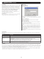
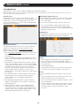
The Connection Screen
A description of the contents of the Connection Screen is given in the following table:
Item Description
Menu Bar The Menu Bar contains two menus; File and Help. The File Menu allows the operator to Create, Save, and Open Work
files.
Server List Each time the WinClient.exe file is run, it searches the User’s LAN segment for B022-Series KVM Switches, and lists
the ones it finds in this box. Double-click on any of the units in this list to connect to it.
Note: For a switch to show up in the Server List, the Enable Device List check box in the Operating Mode page (see
Operating Mode section under Device Management in OSD Operation for details) must be checked and the Program
service port in the Network page (see Network section under Device Management in OSD Operation for details) must
be set to the same number as in the AP Windows Client Port field.
Server This area is used when you want to connect to a B022-Series KVM Switch at a remote location.
• Click on the IP drop-down and select an address from the list. If the address you want is not listed, key in the target
IP address in the IP field, and its port number in the Port field.
• When the IP address and port number have been specified, click Connect to bring up a login dialog box. Provide a
Username and Password as provided by your system administrator and click OK to establish a connection with the
B022-Series KVM Switch.
• When you have finished with your session, click Disconnect to end the connection.
Message List Lists status messages regarding the connection to the B022-Series KVM Switch.
Switch to Remote View Once a remote connection with a B022-Series KVM Switch has been established, this button becomes active. Click it
to switch to the KVM Switch’s Main OSD Page.
The File Menu
The File Menu allows the operator to Create, Save, and Open Work Files. A Work File consists of all the information specified in a Client
session. This includes the items in the Server List and Server IP List.
Whenever a user runs the Client program, it opens with the values contained in the current Work File, i.e. the values that were in effect when
the program was last closed.
The File menu consists of three items:
Item Description
New Allows the user to create a named work file so that its values will not be lost and will be available for future use
Open Allows the user to open a previously saved work file and use the values contained in it
Save Allows the user to save the values presently in effect as the current work file
Exit Exits the AP Windows Client

17
6. KVM Operation
(
continued
)
6.5.3 AP Java Client Login
In those cases in which the Administrator does not want the B022-Series KVM Switch to be available via browser and the remote user is not
running Windows, the AP Java Client provides access to the KVM switch.
After downloading the AP Java Client, go to the location on your hard disk where you downloaded the program and double-click on it to bring
up the connection screen. The AP Java Client connection screen is the same as the Windows version, except that it does not contain a menu
bar with File and Help menus.
Note: When accessing the AP Java Client for the first time, you will be prompted to provide a serial number. This serial number can be found on the CD that
came with your KVM.
1. If your KVM is displayed in the Server List, connect to it by highlighting it and clicking on the Connect button.
Note: For a switch to show up in the Server List, the Enable Device List checkbox in the Operating Mode page (see 7.2.13 Operating Mode for details)
must be checked and the Program server port must match what is set in the Network page (see 7.2.14 Network for details)
2. If your KVM does not display in the Server List, enter in its IP address in the IP server field and click the Connect button.
3. Upon clicking the connect button, you will be prompted to enter your username and password. Enter in your username and password and
press OK.
4. When connected, the Remote View button will be activated. Click on it to access the KVM remotely. Click on the Disconnect button to log
out of the KVM switch.

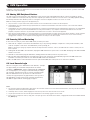
18
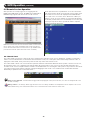
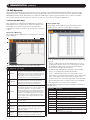
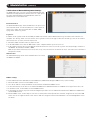
After you have successfully logged in (see Logging Into the
B022-Series KVM Switch section), the B022-Series KVM Switch
OSD Main Page appears with the Port Access tab selected:
All the ports that a user is permitted to access are listed in the
Port Selection panel at the left of the page. Ports to which users
do not have access will not be displayed in their OSD. Double-
click a port icon to access the device attached to it. Once you
switch to a port, its screen displays on your monitor. Depending
on whether you have Full Access or View Only access to the port,
you may or may not be able to operate the remote computer
using your keyboard and mouse.
Note: The AP Client and Local Console versions feature a Control Panel in
the top center of the screen that appears when scrolled over with the
mouse. The web browser version’s Control Panel is only available when a
port has been accessed. (See Control Panel section for details.)
6. KVM Operation
(
continued
)
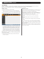
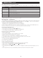
6.6 Remote Session Operation
The Control Panel is provided as a way for the user to optimize and control the remote session. Regardless of whether you initiated a
remote session via the Windows or Java browser and non-browser clients, the control panel and its functionality remain the same. To
display the Control Panel, hover your mouse pointer over the top-center of the remote screen.
The Control Panel consists of an icon bar at the top and two text bars at the bottom. When the mouse pointer is hovered over an icon,
the description of the icon is displayed in the text bar. When the mouse pointer is not over an icon, the text bars display the video
resolution of the selected computer and the IP address of the KVM switch. You can drag the control panel to any location on the remote
screen by hovering over the text bar, and then clicking-and-dragging it. Each of the icons contained in the Control Panel and their
functionality is explained in the sections that follow.
Always on Top / Auto Hide – Click this button to toggle between displaying the control panel all the time, or to allow it to disappear after a few
seconds of inactivity.
Hotkeys / Macros – The Hotkeys / Macros page allows the user to use Hotkeys and Macros to manipulate the remote computers. The user can
enable/disable hotkeys, and create/edit User Macros. The sections that follow describe how these features work.
1024x768@60
192.168.0.60 C1
6.6.1 Control Panel

19
6. KVM Operation
(
continued
)
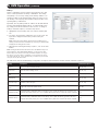
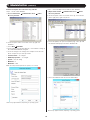
Hotkeys
Various configuration actions related to the keyboard, video and
mouse can be performed via hotkey combinations. The Hotkey
setup utility is accessed by clicking on the Hotkey / Macros icon
and then clicking on the Hotkeys button at the top of the screen.
The Hotkeys screen displays the available hotkeys and their corre-
sponding hotkey combinations.
By default, the only hotkeys that are enabled are the Exit Remote
Location and Substitute Alt Key hotkeys. To enable/disable a hot-
key, simply check/uncheck the box to the left of it. To change a
hotkeys command sequence, follow the steps below.
1. Highlight the desired hotkey and click on the Set Hotkey but-
ton.
2. Key in the desired hotkey combination, one key at a time. The
keys will be displayed in the hotkey column as they are
entered.
Note: Clicking the Cancel button will cancel the recording process.
Clicking on the Clear button will delete any keys that you entered while
keeping the recording process active.
3. When finished entering the hotkey sequence, click on the Save
button.
Note: Clicking the Reset button will restore all of the default hotkey com-
mand sequences, and enable/disable defaults. You can use the same
function keys for more than one hotkey command sequence, as long as
the first key is not the same. For example, you can use [F1, F2, F3] for
one action and [F2, F1, F3] for another, but you cannot use [F1, F3, F2]
once [F1, F2, F3] has been used.
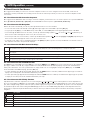
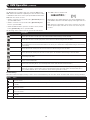
The table below lists the default hotkeys, along with a description of their functions and their default command sequences.
Hotkey Description Command Sequence
Exit Remote
Location
Closes you out of a remote session. [F2, F3, F4]
Adjust Video Opens the Video Settings screen. [F5, F6, F7]
Toggle Control
Panel
Toggles the Control Panel off and on. When off, you will not be able to access the control panel. [F3, F4, F5]
Adjust Mouse
When the local and remote mouse pointers go out of sync, this command brings them back together
again.
[F8, F7, F6]
Video Auto-Sync Performs a video auto-sync. [F6, F7, F8]
Show/Hide Local
Cursor
Toggles the local mouse pointer on/off. [F4, F5]
Substitute Ctrl Key
By default, hotkey combinations that use the Ctrl key, such as [Ctrl, Alt, Delete], get sent to the local
computer. This hotkey allows you to set a substitute Ctrl key that can be used for the remote computer.
F11
Substitute Alt Key
By default, hotkey combinations that use the Alt key, such as [Ctrl, Alt, Delete], get sent to the local
computer. This hotkey allows you to set a substitute Alt key that can be used for the remote computer.
F12

20
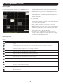
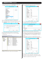
User Macros
The User Macros page allows you to add macros to the KVM
switch that can be performed on any of the connected computers
using the Macro List feature of the control panel. (See Macro List
section under Control Panel in Remote Session Operation for
details.) By default, the User Macros page is displayed when the
Hotkeys / Macros icon is clicked on. To display the page when it
isn’t selected, click on the User Macros button at the top of the
Hotkeys / Macros screen.
6. KVM Operation
(
continued
)
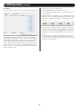
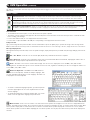
To create a macro, follow the steps below.
1. Click the Add button on the right side of the screen.
2. In the name field that appears, key in a name for the macro
you are adding.
3. With the new macro highlighted, click the Record button on the
right side of the screen. Recording will begin and the following
panel will be displayed in the upper-left corner of the remote
screen.
4. Enter in the macro hotkey sequence and then click the Done
button. You will be returned to the User Macros screen, with
your macro name and hotkey combination added to the list.
Repeat this procedure for any additional macros you wish to
create.
Note: Clicking the Pause button will pause/unpause the recording of
the hotkey sequence. Clicking the Cancel button will cancel the
recording of the hotkey sequence. Clicking the Show button will display
the hotkeys as they are entered.
Page is loading ...
Page is loading ...
Page is loading ...
Page is loading ...
Page is loading ...
Page is loading ...
Page is loading ...
Page is loading ...
Page is loading ...
Page is loading ...
Page is loading ...
Page is loading ...
Page is loading ...
Page is loading ...
Page is loading ...
Page is loading ...
Page is loading ...
Page is loading ...
Page is loading ...
Page is loading ...
Page is loading ...
Page is loading ...
Page is loading ...
Page is loading ...
Page is loading ...
Page is loading ...
Page is loading ...
Page is loading ...
Page is loading ...
Page is loading ...
Page is loading ...
Page is loading ...
Page is loading ...
Page is loading ...
Page is loading ...
Page is loading ...
Page is loading ...
Page is loading ...
Page is loading ...
Page is loading ...
Page is loading ...
Page is loading ...
Page is loading ...
Page is loading ...
Page is loading ...
Page is loading ...
Page is loading ...
Page is loading ...
-
 1
1
-
 2
2
-
 3
3
-
 4
4
-
 5
5
-
 6
6
-
 7
7
-
 8
8
-
 9
9
-
 10
10
-
 11
11
-
 12
12
-
 13
13
-
 14
14
-
 15
15
-
 16
16
-
 17
17
-
 18
18
-
 19
19
-
 20
20
-
 21
21
-
 22
22
-
 23
23
-
 24
24
-
 25
25
-
 26
26
-
 27
27
-
 28
28
-
 29
29
-
 30
30
-
 31
31
-
 32
32
-
 33
33
-
 34
34
-
 35
35
-
 36
36
-
 37
37
-
 38
38
-
 39
39
-
 40
40
-
 41
41
-
 42
42
-
 43
43
-
 44
44
-
 45
45
-
 46
46
-
 47
47
-
 48
48
-
 49
49
-
 50
50
-
 51
51
-
 52
52
-
 53
53
-
 54
54
-
 55
55
-
 56
56
-
 57
57
-
 58
58
-
 59
59
-
 60
60
-
 61
61
-
 62
62
-
 63
63
-
 64
64
-
 65
65
-
 66
66
-
 67
67
-
 68
68


Tripp Lite B022-U08-IP & B022-U16-IP Owner's manual
- Category
- Rack consoles
- Type
- Owner's manual
Ask a question and I''ll find the answer in the document
Finding information in a document is now easier with AI
Related papers
-
Tripp Lite B022-U08-IP & B022-U16-IP Owner's manual
-
-
-
Tripp Lite B022-U08-IP User manual
-
-
-
-
Tripp Lite B020-U08-19-IP User manual
-
Tripp Lite B020-U08-19KTAA User manual
-
Other documents
-
Digitus DS-23300-1 Datasheet
-
iogear GCS1816i User manual
-
 deXlan IP-KVM User manual
-
Avocent Single port KVM over IP switch User manual
-
MicroNet SP1200 User manual
-
Lindy 39405 User manual
-
-
Lanier MP C407SPFG Operating instructions
-
-
