Smeg 91477A540-A User guide
- Category
- Kitchen & houseware accessories
- Type
- User guide
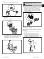
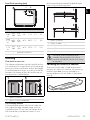
The Smeg 91477A540-A hob is a built-in, class 3 gas hob with a variety of features to make cooking easier and safer. It has automatic ignition, flame failure safety devices, and cast iron pan supports for stability. The hob also features a variety of burner sizes to accommodate different types of cookware, and it is easy to clean with a smooth glass surface.
The Smeg 91477A540-A hob is a built-in, class 3 gas hob with a variety of features to make cooking easier and safer. It has automatic ignition, flame failure safety devices, and cast iron pan supports for stability. The hob also features a variety of burner sizes to accommodate different types of cookware, and it is easy to clean with a smooth glass surface.


-
 1
1
-
 2
2
-
 3
3
-
 4
4
-
 5
5
-
 6
6
-
 7
7
-
 8
8
-
 9
9
-
 10
10
-
 11
11
-
 12
12
-
 13
13
-
 14
14
-
 15
15
-
 16
16
-
 17
17
-
 18
18


Smeg 91477A540-A User guide
- Category
- Kitchen & houseware accessories
- Type
- User guide
The Smeg 91477A540-A hob is a built-in, class 3 gas hob with a variety of features to make cooking easier and safer. It has automatic ignition, flame failure safety devices, and cast iron pan supports for stability. The hob also features a variety of burner sizes to accommodate different types of cookware, and it is easy to clean with a smooth glass surface.
Ask a question and I''ll find the answer in the document
Finding information in a document is now easier with AI
Related papers
-
Smeg 91477A686 User guide
-
Smeg Classic PS9062 User manual
-
Smeg COLONIALE SRV864POGH GASSTOPP User manual
-
-
-
-
-
-
-
