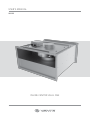
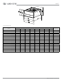
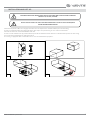
Vents VKP EC is an inline centrifugal fan designed for supply and exhaust ventilation systems in commercial, office, and industrial premises. It features a synchronous electronically commutated motor for energy efficiency, low noise operation, and continuous operation capability. The fan can be mounted in any position with respect to the airflow direction and requires no special fixing in case of direct connection to air ducts.
Vents VKP EC is an inline centrifugal fan designed for supply and exhaust ventilation systems in commercial, office, and industrial premises. It features a synchronous electronically commutated motor for energy efficiency, low noise operation, and continuous operation capability. The fan can be mounted in any position with respect to the airflow direction and requires no special fixing in case of direct connection to air ducts.


-
 1
1
-
 2
2
-
 3
3
-
 4
4
-
 5
5
-
 6
6
-
 7
7
-
 8
8
-
 9
9
-
 10
10
-
 11
11
-
 12
12
-
 13
13
-
 14
14
-
 15
15
-
 16
16


Vents VKP EC is an inline centrifugal fan designed for supply and exhaust ventilation systems in commercial, office, and industrial premises. It features a synchronous electronically commutated motor for energy efficiency, low noise operation, and continuous operation capability. The fan can be mounted in any position with respect to the airflow direction and requires no special fixing in case of direct connection to air ducts.
Ask a question and I''ll find the answer in the document
Finding information in a document is now easier with AI
Related papers
-
Vents VKP, VKPI, VKPF, VKPFI, VKP EC, VKPI EC User manual
-
Vents VKPFI Centrifugal Rectangular Duct Fan User manual
-
-
Vents VKPI EC User manual
-
-
-
-
-
Vents VKPD User manual
-