Lowrance GlobalMap 1000 User manual
- Category
- Navigators
- Type
- User manual


WARNING!
USE THIS
MAPPING UNIT ONLY AS AN AID TO NAVIGATION.
A
CAREFUL
NAVIGATOR NEVER RELIES ON ONLY ONE METHOD
TO
OBTAIN POSITION
INFORMATION.
The
background maps
built
into this unit are not intended for
navigation.
The
accuracy
of these
maps
has not been verified. The
maps
are derived
from U.S. Government
sources which
rely
on
ground
and aerial
surveys
and satellite data.
Since there can be inaccuracies in the data used to
create the
map
and the
maps
resolution,
and
position
inaccuracies in
the
navigation
system, you
should use caution when
using
this
product.
CAUTION
When
showing navigation
data to a
position (waypoint),
this unit will show
the
shortest,
most direct
path
to the
waypoint regardless
of obstacles.
Therefore,
the
prudent navigator
will not
only
take
advantage
of all
available
navigation
tools when
travelling
to a
waypoint,
but will also
visually
check to make certain a
clear,
safe
path
to the
waypoint
is
always
available.
NOTICE!
As of this
writing,
the
Department
of
Defense
(DOD)
has not declared the
GPS
navigation system operational.
The
system
is still in a
testing phase.
Satellites
can be
turned off or
accuracy
can be
degraded
at will
by
the
system operators.
Remember
this
if
you
use a GPS receiver as the
position input
to the
GlobalMap
1000.
C-MAFI
CMAPTM
The CMAPTM database
is not intended as a
replacement
of official
nautical charts which are
required
for safe
navigation.
Copyright®
1993 Lowrance
Electronics,
Inc.
All
rights
reserved.
All features and
specifications subject
to
change
without notice.
All screens in this manual
are simulated.
NOTES:
PDF compression, OCR, web-optimization with CVISION's PdfCompressor

NOTES:
TABLE OF CONTENTS
INTRODUCTION
MOUNTING
BRACKET MOUNT
IN-DASH MOUNT 2
POWER CONNECTIONS 3
DATA INPUT AND OUTPUT CONNECTIONS 4
DGPS BEACON RECEIVER 7
MAPLINKIM 10
LOWRANCE GPS MODULE INSTALLATION II
KEYBOARD 14
GE1TING STARTED INITIALIZATION 15
DGPSSETUP 16
LOWRANCELGC-1 GPS MODULE 17
COLD START 19
LGC-1 GPS MODULE TEST 19
MAPPING/NAVIGATION/STEERING DISPLAYS
20
MAP SCREEN 21
MAPPING OPTIONS 23
CARTRIDGE
SWITCH
25
C-MAP SETUP 25
CURSOR 26
TRAIL PLOTTER 27
EVENT MARKER 29
NAVIGATION SCREEN 31
STEERING SCREEN 32
CDI.
RANGE
33
SATELLITEJDGPS INFORMATION SCREEN 33
CUSTOMIZE SCREENS 35
WAYPOINT NAVIGATION 37
HOW TO SAVE A WAYPOINT 37
QUICK SAVE METHOD 37
VIEW AND SAVE METHOD 37
EDITING A WAYPOINT 38
WAYPOINT SYMBOLS 39
GOTOAWAYPOINT 40
CANCEL NAVIGATION 40
ERASE A WAYPOINT 41
WAYPOINT DISPLAY 41
ROUTES 42
CREATING A ROUTE 42
NAMEA ROUTE 42
WAYPOINT
SELECTION 43
REMOVEAWAYPOINT 46
EDIT WAYPOINT 46
ERASEAROUTE 46
FOLLOWING A ROUTE 47
GPS ALARMS 49
ARRIVAL ALARM 49
XTE
(CROSS
TRACK
ERROR)
ALARM 50
ANCHOR ALARM 50
PERPENDICULAR ALARM SI
NMEA OUTPUT SI
UNITS OF MEASURE 52
CONTRAST,
VOLUME,
AND LIGHT ADJUSTMENT 53
MAN OVERBOARD 53
DATIJMS 55
PCF
(Position
Correcllon
Factor)
56
POSITION FILTER 58
PRESET
58
GPS SIMULATOR 58
LAST-MINUTE CHANGES
59
PDF compression, OCR, web-optimization with CVISION's PdfCompressor


6. TRAIL PLOT
If
you
turn the
plot
trail
recording
off,
(using
the Trail
Recording
function
on the
"Mapping
Setup" menu)
then the
GlobalMap
1000 will
stop
plotting your
trail.
However,
it will show
your
trail on the
map up
to the
point
that
you
turned it off.
7. TRAIL PLOT
There is a maximum of 2000 dots available to
plot
a
trail.
8. EVENT MARKER
Pressing
the EVENT
MARKER
key
twice
puts
the last used marker at
your
present
position
or at
the cursor
position
if it's
displayed.
9. EVENT
MARKER
You can't erase event
markersfrom the
displaywhen
it's in the "course-
up"
mode.
10.The
storage temperature
for
your
unit is from -4
degrees
to +167
degrees
Fahrenheit
(-20
to ÷75
degrees Celcius).
Extended
storage
temperatures higher
or lowerthan
specified
will cause the
liquid crystal
display
to fail. Neither this
type
of failure nor its
consequences
are
covered
by
the
warranty.
For more
information,
consult the
factory
customer service
department.
INTRODUCTION
The
GlobalMap
1000 is a
high
quality,
wide screen
mapping
unit with
performance
that is second to
none
in its class.
Using
menu features and
"soft-key" operation,
the
GlobalMap
1000 is also one of the easiest-to-use
products
that Lowrance has ever built. It sets
new standards in
mapping
versatility
and
performance
by combining
a built-in reference
map (back-
ground map)
with the
ability
to read
mapping cartridges (requires optional
MapLinkTM
cartridge reader.)
The
displayand keyboard
are also
lighted
for
night operation.
The
GlobalMap
1000's built-in
background map
includes
virtually
the
whole
world, however, over7o%
of the
map's
detail is in
the
48-contiguous
states, HawaD,
and southern Canada. If
you
install the
MapLink cartridge
reader,
the
GlobalMap
1000 can
display highly
detailed charts available on
C-Map cartridges, covering
most coastal areas around the world. In the
future,
Lowrancewill also have
cartridges
availablethatcover
many
inland
areas.
MOUNTING
-
Bracket
Mount
Install the
GlobalMap
1000 in
any
convenient
location,
provided
there is
clearance behind
the unit when it is tilted forthe best
viewing angle.
Holes
in the bracket base allow wood screw or
through-bolt mounting.
You
may
need to
place
a
piece
of
plywood
on the back of thin
fiberglass panels
to
secure
the
mounting
hardware. Make certain there is
enough
room behind
the unit to attach the
power
and
MapLink
cables
(if
used).
The smallest hole that will
pass
the
power plug
is one inch. After the hole
is
drilled,
pass
the
MapLink
connector
up through
the hole first
(if used),
then
pass
the
power
cable
down
through
it.
60
After the cables have been
routed,
fill the hole with a
good
marine
sealing
compound.
Offset the bracket to cover the
hole. Route the
power
and
MapLink
cables
through
the slot in
the back of the bracket.
SLOT
PDF compression, OCR, web-optimization with CVISION's PdfCompressor

IN-DASH MOUNTING
To turn the simulator
on, press
the MENU
key
two
times. Now
press
the
The
GlobalMap
1000 can be installed in the dash with the
supplied
hardware if the dash is 1/2" thick or less.
Determining
the dash thickness
can be
difficult,
however,
if
you
remove a
gauge
from the
dash, you
can
easily
measure thethickness.
Trythis
in an areathat's closeto the location
that
you
wish to install the
unit
since the thickness can
vary significantly
in some boats. Make certain there is clearance behind the dash forthe unit
and there is
enough
room to
tighten
the bolts on both sides of the unit.
.400" radius
(4 places)
7,625'
T
"
DASH CUTOUT
'—
Once
you've
determined the location forthe
unit,
cut the hole
according
to
the
drawing
shown above. Measure
carefully
before
cuttingl
After
cutting
the
dash,
place
the
gasket supplied
with the
GlobalMap
1000 around the
unit and
place
the unit in the hole.
Supplied
with the
GlobalMap
1000 are rubber
pads, bolts, washers,
and
cam
clamps
to attach it to the dash. Peel the adhesive
backing
off the
rubber
pads
and
place
one on each side of the unit
in
the
location where
the cam
clamp
will touch the back side of the dash.
Usingthe
hardware
supplied
with the
unit,
attach the unitto the dash.
Looking
atthe back of the
unit,
make certain that the cam
clamp
on the left side of the unit
is
pointing
down and the cam
clamp
on the
right
side of the unit is
pointing up
before
you
start
tightening
the bolts.
[ LOWRANCJ
GO
1
key
next to the "Simulator" label. The screen clears
and the simulator
begins operation.
To turn the simulator
off,
either
repeat
the above
steps
or turn the unit off.
1.
C-MAP
LAST MINUTE CHANGES & ERRATA
The
GlobalMap
1000 won't
operate
in the course
up
mode when the C-
MapTM
background map
is in use.
2. C-MAP
Buoys
and other
naviga-
tional
aids have additional
information available
when
using
a C-MAP
cartridge.
To view this
data,
move the
cursor on
top
of the desired
symbol,
as
shown at
right.
Now
pressthe
ENT
key.
The
screen shown below
ap-
pears.
An information
box
shows on the
screen, giving
information
about the se-
lected
symbol.
To erasethis
message
box,
press
the CLR
Iiuforriat ion
3. ROUTES and WAYPOINTS
If an asterisk
*
appears
next
to a
waypoint
in the list of
waypoints
used in a
route,
then that
waypoint
has
changed
since it was added
to a route. For
example,
if
you
use
waypoint
number
one in a route and later
change
the
waypoint's
location,
then the
GlobalMap
1000 will
place
an asterisk
next to the
waypoint's
number in
the route list. This alerts
you
to
any
change
made to
any waypoint
used
in a
route,
including
name,
symbol,
and
position.
4. CURSOR
The cursor is not
available when the
map
is in the "course
up"
mode.
2 59
'a
15.5
H 25°46.42?'
LI
8OU4.UE'l4.1O
key.
BOLT
RUBBER PAD
CAM CLAMP
(TURNED
DOWN)
RUBBER
PAD
BOLT
CAM CLAMP
(TURNED UP)
CLR to
Benouc
5:Ofl22p
PDF compression, OCR, web-optimization with CVISION's PdfCompressor

POSITION FILTER
No matter
what kind of
__________________
radionavigation
input
you're
using
with the
GlobalMap 1000, ___________________
"jitter"
orsmall
position
changes
______________ ______
will show on the
display
even
when
you're
not
moving.
For
______________________________
example,
the GPS module or
_____
____
antenna is mounted
high
above
the
deck, position changes
will
______________________________
occur
as the boat rolls in the
____________________________
waves.
The
position
filter will
average
the
jitter, showing
a smoother
position
and
navigation display.
(The jitter
affects not
only
the
position,
but all other
displays including
course over
ground
and
speed
over
ground.)
There arethree
settings:
off,
low,
and
high.
When the
GlobalMap
1000 is firstturned on or is
preset,
the
filter is turned
off. To set the
filter,
press
the MENU
key
twice. The screen
shown above
appears.
Now
press
the
key
next to the "Filter" label until the
check mark is on the desired
setting.
Press
the CLR
key
to exit this screen
and
put your change
into
effect.
PRESET
The
preset
feature returns all of the
GlobalMap's
settings
to their
original
factorysettings.
This resetsthe units of
measure, speakervolume, display
contrast,
and more.
However,
this doesn't
erase
any
event
markers,
waypoints
or routes.
To
preset
the
unit, press
the MENU
key
two times. The screen shown
above
appears.
Now
press
the
key
next to the °PresetUnit to
Factory
Settings"
label. A
message appears, warning you
that this will
preset
the
unit. Press the ENT to
preset
the unit or the CLR
key
to exit without
presetting.
If
you
press
the ENT
key,
the menu screen
disappears
and the
GlobalMap
1000 returns to the
mapping
screen. All units will be returned
to their
factory settings.
SIMULATOR
The
GlobalMap
1000 has a simulator feature that shows
your present
position
travelling
a
preset
course from
Miami,
Florida. All
navigation
features
of the unit
operate,
also. A
recurring message appears alerting
you
that the simulator
mode is enabled. DON'T USE THIS UNIT FOR
NAVIGATION
WHEN
THE SIMULATOR
IS OPERATING!
POWER CONNECTIONS
The
GlobalMap
1000 worksfrom atwelve-volt
batterysystem.
Forthe best
results,
attach the
power
cable
directly
to the
battery.
You can attach the
power
cable
to an
accessory
or
power
buss,
however
you may
have
problems
with electrical interference.
Therefore,
it's saferto
go
ahead and
attach the
powercable directlyto
the
battery.
If the cable istoo
short,
splice
#18
gauge
wire onto it. The
power
cable has
four
wires; red, black,
green,
and white. Red is the
positive
lead,
black is
negative
or
ground.
Make
certain to attach the in-line fuse holderto
the red lead as closeto the
power
source as
possible.
For
example,
if
you
have to
extend the
power
cable to
the
battery
or
power
buss,
attach one end
of the fuse holder
directly
to the
battery
or
power
buss. This will
protect
both the
unit and the
power
cable
in the event of a short. The
GlobalMap
1000 uses
a
3-amp
fuse.
IMPORTANT!
Do not use this
product
without a
3-amp
fuse wired into the
power
cable!
Failure to
use a
3-amp
fuse will void
your warranty.
TO
NMEA 0183
VERSION 2.0
INTERFACE
TO
LOW RAN c F
GPS MODULE
TO P' CONNECTOR
ON GLOBALMAP 1000
TO
NMEA 0180 or
0183
58
3
Customtize Display
a-
Units Of fleasure
)attut
Translations
Filter
10FF
OLOW a
High
Sinulator a ON 10FF
Preset Unit To
Factory Settings
—
a
More
VERSION 1.5
INTER FACE
GlobalMap
1000
POWER CONNECTIONS
PDF compression, OCR, web-optimization with CVISION's PdfCompressor

DATA INPUT AND OUTPUT
CONNECTIONS
In order for the
GlobalMap
1000
to show
position
information,
it
requires
navigation
data from
either
a
Loran-C, Decca,
or GPS receiver than can
send the data in
NMEA 0183 version 1.5 or 2.0 format. If the NMEA
input
is not
used,
then the
Lowrance LGC-1 GPS receiver can be used.
The
wiring
connections for the NMEA 0183 version 1.5 are different than
the ones used
forthe NMEA 0183 version 2.0. If
you
are
using
version
1.5,
then
use
the
green
and black wires on the
GlobalMap's powercable.
If
you
are
using
version
2.0,
then
you'll
be
using
the four shielded wires
on the
GlobalMap's
power
cable.
If
you're using
the
Lowrance LGC-1 GPS
module, simply plug
its
cable
directly
into the
in-line connector on the
GlobalMap's power
cable. This
sends
navigation
data
directly
to the
GlobalMap
without
using any
NMEA
input.
You
can,
if
desired,
use either NMEA
output
to drive another device
while
using
the LGC-1 as an
input.
The
GlobalMap
1000 also has the
provision
fora
DGPS beacon receiverforuse with the LGC-1 GPS module.
TO
NMEA 0183
VERSION 2.0
INTER FACE
(FOUR
SHIELDED
WIRES)
indicates what the
possible
er-
ror is. This
feature should al-
ways
be reset to zero
(0)
when
finished with that chart.
For
example,
suppose you
are
stopped
at a
location that is
accurately
marked on a
chart.
Your
unit shows a
longitude
position
that is .010
degrees
less than the one on the chart.
Using
the Position Correction
Factor
(PCF)
Offset
feature,
you
makethe unit read the same as the
chart.
If
you
move,
the unit will
continuously
add the
change
to all
position
displays.
This makes it more
closely
match the datum used
by
the chart.
For this
reason,
you
should be careful when
entering
the PCF offset. This
offset is saved in
memory.
It doesn't
change
when the unit is turned off.
However,
a Preset does erase the PCF factor.
To set the PCF
factor,
first
press
the MENU
key
two
times,
then
press
the
key
next to the "Datum Translations label.
Finally, press
the
key
next to
the "PCF" label at the bottom of the
display.
The screen shown above
appears.
Nowenterthe correction
foryour
location.
Remember,
this isthe difference
between the location shown on the
present position display
and the
position
shown on the chart. In this
example,
we
have entered 0 de-
grees,.012
minutes north latitude and 0
degrees,
.068 minutes
east
longitude
as the PCF offset. That is
the
difference
between the
present
position
shown on the unit and our
position
shown
by
the chart. In other
words,
our
position
shown on the unit is 0.012 minutes south
and 0.068
minutes
wt
of the
position
shown on the chart.
After
you've
entered the desired
offset, press
the
key
next to the "PCF
Mode ON OFF" label. Thisturns the
FCFcorrection
factorthatyou
entered
on. To leave this
screen, press
the CLR
key.
This also
puts
your changes
into effect.
To turn these
changes
off,
return to this screen and
press
the
key
next to
the "PCF Mode ON OFF" label.
Remember, presetting
the unit also
erases
any
PCF
offset,
thereby turning
it off.
TO"P"OONNECTOR
ON
GLOBALMAP 1000
LOWRANCE
OPS MODULE
To
NMEA
0180
or
0183
VERSION 1.5
INTERFACE
4 57
PDF compression, OCR, web-optimization with CVISION's PdfCompressor

There aretwo boxes on the
left
side of the screen. One reads
"Source
Datum,
the other is
'Display
Datum." Before
chang-
ing
the
Datum,
you
need to
know which datum the
naviga-
tion
receiversupplying position
data to the
GlobalMap
1000 is
using.
For
example,
all Low-
rance GPS receivers
(includ-
ing
the LGC-1 UPS
receiver)
use WOS
84;
all
Lowrance
Loran-C receivers use WGS 72.
The
display
datum box shows the datum
currently displayed
on the
mapping
screen
by
the
GlobalMap
1000. If the
display
datum is different
from the source
datum,
the
GlobalMap
1000 "translates" the source datum
to the
displayed
one. This lets
you display
a
map using any
datum on the
list on the
right
side of the screen.
To
change
either the source or
displayed
datum,
first
press
the
key
on the
right
side of the screen next to the desired box
that
you
wish to
change.
Then
press
the
up
or down arrow
keys
to move
highlight
the datum
you
wish to use. For
example,
to
change
the source datum
from WOS 84 to
WGS
72,
simply pressthe key
nexttothe "Source Datum"
label,
then
press
the down arrow
key
until "WGS 72" is
highlighted.
When the source box
shows the correct
datum, press
the ENT
key.
This saves the datum
displayed
in the source box.
Once
you
have the desired datums
showing
in both the source and the
display
boxes,
pressthe
CLR
key.
This unit returnsto the
mapping
screen,
using
the datums
you specified.
The white and
green
wires are for a NMEA
0183,
version
1.5 interface.
The
GlobalMap
1000 sends data to other electronic
navigation
devices
through
the white wire and receives NMEA data
through
the
green
wire,
If the white and
green
wires are not
used, tape
their ends so that
they
cannot short.
To connect a device to the
GlobalMap
1000's NMEA 0183 version 1.5
input,
attach a twisted
pair
cable
from
the device's NMEA
output
to the
green
and black wires on the
GlobalMap
Il's
power
cable. Solder the
ground
conductor of the twisted
pair
to the black wire on the
power
cable.
To connect a
device
to
the
GlobalMap
1000's NMEA
0183
version
1.5
output,
attach a twisted
pair
cable from the device's
NMEA
input
to the
white and black wires on the
GlobalMap
Il's
power
cable.
Solder the
ground
conductor of the twisted
pair
to
the
black wire
on the
power
cable. See the other instrument's manual for more
wiring
instructions.
The default for both the source and
display
datums is WGS 84.
PCF
(Position
Correction
Factor)
Another method used to reduce the error factor between datum
is
called
PCF,
or Position Correction Factor. This unit
gives you
the
capability
to
move or "offset" the
position
shown on the
display
to match
the one on the
chart. The unitwill add this offset or PCFto all
position displays
at alltimes.
Remember,
the
position
error on
.any radionavigation system
is
very
dynamic
and the PCF offset should never be used in an
attempt
to cancel
the error. In
general
terms this feature should
only
be used if
your map
56 5
N%IEA
0183,
VERSION 1.5 WIRING CONNECTIONS
Australia
66
Australia 84
European
5J
European
79
Geodetic
49
MAD 2? CONUS
Ord.
Suruey
G.ll.
Tokyo
UGS 72
UGS 84
GLOBALMAP
1000'S
POWER GABLE
OTHER DEVICE'S NMEA 0183,
VERSION 1.5 OUTPUT CABLE
BLACK
GLOBALMAP 1000
RECEIVING
NMEA 0183 VERSION 1.5 DATA
PROM ANOTHER DEVICE
GLOBALMAP 1000 OTHER DEVICE'S NMEA
0183,
POWER CABLE VERSION 1.6 INPUT CABLE
BLACK
GLOBALMAP 1000
SENDING
NMEA
0183
VERSION
1.5
DATA I
ANOTHER DEVICE
PDF compression, OCR, web-optimization with CVISION's PdfCompressor

NMEA VERSION 2.0
WIRING CONNECTION
The shielded
red, black,
white and
green
wires are for a NMEA
0183,
version 2.0 interface. This is a
shielded,
balanced line interface. Do not
use the shield on these wires! Trim the shield
back,
away
from the
splice
when
you
attach wires from another device to the
GlobalMap
1000. The
GlobalMap
1000 sends data
(transmits)
to another electronic
navigation
device
through
the
shielded white and
green
wires and receives NMEA
data
through
the shielded red and black wires. If the
any
of these wires
are not
used, tape
their
ends so that
they
cannot
short.
To send data to the
GlobalMap 1000,
connect the other device's NMEA
0183 version 2.0
output
to the
GlobalMap's
NMEA 0183 version 2.0's
input (GlobalMap
receives
data) by attaching
a twisted
pair
cable from
the other device's NMEA
output
to the shielded red and black wires on
the
GlobalMap
Ii's
power
cable.
In
order
for the
GlobalMap
1000 to send data to
another
device,
connect
the other device's NMEA 0183 version 2.0
input
to the
GlobaiMap's
NMEA 0183 version 2.0's
output (GlobalMap
sends
data) by attaching
a twisted
pair
cable from the other device's NMEA
input
to the shielded
white and
green
wires on the
GlobalMap
il's
power
cable.
To add the
position
shown at the
top
of Man Overboard Information menu
to the
waypoint
table,
simply press
the
key
next to the "Covert Man
Overboard to
Waypoint"
label. The
GlobalMap
1000 will
assign
that
position
to the first available
waypoint
number in the
waypoint
table. This
waypoint
can be edited the same as
any
other
waypoint
on the
list,
including
the
name,
symbol,
and
position.
Remember,
repeated pressing
of the Man Overboard
key
does
not
repeatedlysave your present position!
The unit
only
savesthe
position
the
first time the Man Overboard
key
is
pressed.
To save a new Man
Overboard
position,
you
must first reset Man Overboard
by Dressing
the
key
next to the "Reset Man
Overboard" label on the Man Overboard
Information menu.
You can
navigate
to a
waypoint
using
the
Waypoint
Recall feature at
any
time,
however this
stops
the
GlobalMap
1000
from
navigating
to the Man
Overboard
position.
Remember,
saving
the victim is the
primary goal. Try
all
options
to rescue
the
person immediately
after the accident
happens. Training
and educa-
tion are also
good
accident
preventative.
The Coast Guard has excellent
safety
courses.
Instruct
all
members on
board
your
boat
on
safety
procedures
before
leaving
the dock. Make certain all on board know what
to
do before
any emergency
occurs.
DATUMS
The GPS
navigation system
relies on
complex
mathematical calculations
to determine
your position
based on satellite data and other factors. One
factor is the Earth's
shape.
Since the Earth is not a true
sphere,
variations
in the calculations have to be made to accommodate deviations. To make
matters more
complex,
not
everyone
uses the same data to determine
whatthe deviations are. The size and
shape
of the
ellipsoids
that are used
to
approximate
the earth's surface are
improved
often. This can lead to
errors if
your navigation
device uses one
ellipsoid,
while
your
chart uses
a different one. The term used for these
ellipsoids
is "Datum."
To reducethe errorfactor between
datum,
this unit
gives you
the
capability
to select the datum used
bythe GlobalMap
1000 when
displaying
the
map.
You can select a new datum from a list or enter a correction offset based
on
latitude/longitude.
To
change
the
datum,
first
press
the MENU
key
two times. Now
press
the
key
next to the "Datum Translations" label. The screen shown at
thetop
of
the next
page appears.
WHITE
TRANSMIT WIRES
GREEN\"\
GLOBALMAP 1000
—
BLACK
r
OTHER DEVICE'S
RED/
NMEA OUTPUT
GLOBALMAP 1000 RECEIVE DATA FROM NMEA
0183,
VERSION 2.0 ONLY
BLACK
OTHER DEVICE'S
NMEA INPUT
GLOBALMAP 1000
fNQ
NMEA
0183,
VERSION 2.0 DATA TO DEVICE ONLY
1ECEIVE WIRES
BLACK
RED
SEND AND RECEIVE NMEA 0183 VER. 2.0 DATA
6 55
PDF compression, OCR, web-optimization with CVISION's PdfCompressor

you navigate
back to the man
1-;—i
For the
GlobalMap
1000 to both
send and receive NMEA
0183,
version
Man Overboard
Information
Onceyou'vesaved
aMan Over-
board
position,
the
unit shows
navigation
data
to that
position
until
you
reset the Man Over-
board
function,
turn the unit
off,
__________
or use the Cancel
Navigation _________
feature. _____________________
To reset the Man Overboard or
view more information
about
it, press
the WAYPT/ROUTE
key.
Now
press
the
key
next to the "Man
Overboard Information" label. The screen shown
below
appears.
Your
position, time,
and
date
when the Man
Overboard
key
was
pressed
shows at
the
top ______________________________
of the screen. If
you
wish to
save
your present position
in-
stead of the
one shown at the
top
of
the
screen,
pressthe key
next to the "Save New Man
Overboard"
label. If
you're
not
currently navigating
to the Man
Overboard
position
and wish to
do
so,
press
the
key
next to the
"Navigate
to Man Overboard
Location" label. The
GlobalMap
1000 will
instantly
show
navigation
data to
the
position
shown at the
top
of
this screen.
Once the Man
Overboard
key
is
pressed, your present position
is saved
in
memory.
Pressing
the
key again
won't save
your position again,
instead
a
warning message
will
appear.
This
prevents
the inadvertent loss of the
current Man Overboard
position by
someone
accidentally pressing
the
Man Overboard
key.
To
resetthe Man Overboard function which "arms' the
key, press
the
key
next to the "Reset Man Overboard" label on the menu
shown above.
The
GlobalMap
1000 doesn't save the Man Overboard
position
in
the
waypoint
table.
However,
it
does save the
position
on the Man Overboard
Information screen.
2.0 data
,
see the
wiring diagram
at the bottom of the
previous page.
Remember,
under
no circumstances should the shields on the
GlobalMap's
wires be connected to the
ground
on the other device. See
the other instrument's manual for more
wiring
instructions.
NOTE
When
using
the shielded wires
(NMEA
0183 version
2.0),
do
not connect
the black wire to the
battery's
ground.
DGPS BEACON RECEIVER
CONNECTIONS
If the Lowrance LGC-1 OPS receiver is connected to the
GlobalMap
1000,
a differential
(DGPS)
beacon receiver
can also
be
connected,
giving you higher accuracy positions
in the area covered
by
the beacon
receivers. The unshielded
green
wire
(used
with the NMEA version 1.5
data)
on
the
power
cable is used for the differential
(DGPS)
beacon
receiver
input.
At this time
two DGPS beacon receivers can be con-
nected to the
GlobalMap
1000. These are the Starlink model MRB-2A
and
Magnavox
MX-50R. Please note that the
GlobalMap
1000 will not
send
NMEA 0183 data when the
Magnavox
MX-50R receiver is con-
nected.
To connect a beacon receiver to the
GlobalMap 1000,
attach a twisted
pair
cable from the beacon receiver's
output
to the
green
and black
wires
(unshielded)
on the
GlobalMap
1000's
power
cable as shown
below. Solder the
ground
conductor of the twisted
pair
to the black wire
on the
power
cable.
After the beacon receiver is connected to the
GlobalMap
1000,
see the
"Input/Output Setup"
section for information on
selling
the communica-
tion
parameters
for the DGPS
receiver.
GLOBALMAP 1000'S
POWER CABLE
overboard
position.
0.04
N 25°41.951' W80c12.0842
15.O
2:51:511p
N 25°41.931'
Z:51:4lprl
U 80°
12.1111' 10/28/1993
WIRE
DGPS RECEIVER'S
NMEA 0183 OUTPUT CABLE
BLACK
54
7
GLOBALMAP 1000 RECEIVING
DATA FROM DGPS BEACON
RECEIVER
PDF compression, OCR, web-optimization with CVISION's PdfCompressor

CONTRAST
, VOLUME,
and LIGHT ADJUST
The
GlobalMap
1000's
display
contrast, speaker
volume,
and
light
brightness
are
adjustable
from
the
same menu screen.
To
adjust any
or all of these
features,
press
the MENU
key,
then
press
the
key
next to the
"Contrast, Volume,
and
Bright-
ness' label.
The screen shown
at
right appears.
Three vertical
bar
graphs appear
on this
screen. When
you
first enter
this
screen,
the contrast is
ready
for
adjustment.
To
change
anotherfeature on this
screen,
simply press
the
left or
right
arrow
key
to
highlight
the desired feature. Then
press
the
up
or
down arrow
keys
to increase or decrease
the level. When
you
have
everything
on this
page
adjusted
as
desired, press
the CLR
key
to
exit.
Note: To turn the
lights
on, simply press
the ON
key again afterturning
the
GlobalMap
1000 on. To turn the
lights
off,
press
the ON
key again.
MAN OVERBOARD
One of
boating's mostterrifyingevents
is
having
a friend
orfamily
member
fall overboard. This situation
can be
deadly
on
any body
of
water,
fresh or
salt. It's
particularly dangerous
at
night
or if
you're
out of
sight
of land. Of
course,
the first
thing
to do
is remain calm and
try
all standard
safety
measures to
try
and rescue the
person.
If
you
lose
sight
of the
person, you
can use the
GlobalMap
1000
to
help
start a search
pattern.
Once
you're
back at the helm after initial rescue
efforts have
failed,
press
the
GlobalMap
1000's MAN OVERBOARD
key.
A
message appears:
"Now
Navigating
to Man Over-
board Location". A screen
simi-
lar to the one at
right appears.
Your
position
at the time
you
pressed
the Man Overboard
key
is shown
by
a box with the let-
ters "MOB" inside. All
digital
navigation displays including
Distance
(DTG),
Bearing
________
(BRG),
Course
(COG),
Speed
Over Ground
(SOG),
and Time
To Go
(TTG)
show data
that let
N 2s041.951 w 80
12.084'.
SAMPLE WIRING DIAGRAMS
GLORALMAP 1000 RECEIVING NMEA
0183,
VERSION 1.5 DATA FROM
NAVIGATION RECEIVER.
GREEN
WIRE
GLOBALMAP 1000 RECEIVING NMEA
0183,
VERSION 2.0 DATA FROM
NAVIGATION RECEIVER.
SHIELDED RED
WIRE
GLOBALMAP 1000 RECEIVING NMEA
0183,
VERSION 1.5 DATA FROM
NAVIGATION RECEIVER AND SENDING NMEA
0183,
VERSION 1.5 DATA TO
ANOTHER DEVICE.
8
53
O.O4MI
15.O
PDF compression, OCR, web-optimization with CVISION's PdfCompressor

UNITS
OF MEASURE
The units of measure used in the
GlobalMap
1000 are
adjustable.
This
includes
time,
distance, altitude, direction, speed,
and
depth.
To
change
any
of the
settings,
first
press
the MENU
key
two
times. Now
press
the
key
next to the "Units of Measure"
label. The screen shown below
appears.
Simply press
the
key
next to the label that
you
wish to
change
until the
check mark in that
label moves to the desired
setting.
Press the CUR
key
to exit this screen and return to a
mapping
or
navigation
screen.
Time
Time can be shown on the dis-
playsasl2hour(A.M. -P.M..),
24 hour
(2:00
P.M..= 1400
hours),
or UTC time.
Normally,
the
GlobalMap
1000 shows
your
local time in 12 hour for-
mat,
but
you
can also
display
UTC time
(which
is the time
at
Greenwich,
England).
(Tine 112 Hour a 24 Hour
a
IJTC
3
(Distance
a NM IMI a 1(11
(Altitude IFT o
M
r
Direction
ITrue a Magnetic
—a
Speed
a 1CM 1MPH a EPl1
:r*wS
IDepth
IFT a PA a 1
Distance
The distance can be
shown in nautical miles
(NM),
statute miles
(Ml),
or
kilometers
(KM).
Altitude
Press the
key
next to the Altitude label to switch it from feet to meters.
Direction
(True
and
Magnetic Position)
True north is the
top
of the world. It's where all lines of
longitude converge.
Magnetic
north is the location
ourcompasses point.
It lies several hundred
miles to the south of true
north,
at a location in Canada.
The
GlobalMap
1000 can
display navigation
information in
magnetic
or
true. When it's turned on for the first time true is used.
Press the
key
next
to the "Direction" label to switch it to
magnetic.
Speed
The
GlobalMap
1000 can
display speed
in knots
(KN),
statute miles
per
hour
(M.P.H.),
or kilometers
per
hour
(K.P.H.).
The default
selling
for
speed
is statute
miles
per
hour.
Depth
Water
depth readings
shown on the
C-Map
charts can be shown in feet
(FT),
fathoms
(FA),
or meters
(M).
GLOBALMAP 1000 RECEIVING NAVIGATION DATA FROM LOWRANCE
LGC-1 GPS MODULE
PLUG LGC-1 GPS MODULE CABLE INTO
CONNECTOR ON GLOBALMAP 1000'S
POWER CABLE.
GLOBALMAP 1000
RECEIVING NAVIGATION DATA FROM LOWRANCE
LGC-1 GPS MODULE AND DGPS BEACON RECEIVER.
PLUG
LGC-1 GPS MODULE CABLE INTO
CONNECTOR ON GLOBALMAP 1000'S
POWER CABLE.
1.5
CABLE)
GLOBALMAP 1000 RECEIVING NMEA
0183,
VERSION 2.0 DATA FROM
NAVIGATION RECEIVER AND SENDING NMEA
0183,
VERSION 1.5 DATA TO
ANOTHER DEVICE.
52
9
PDF compression, OCR, web-optimization with CVISION's PdfCompressor

MAPLINKTM
The
GlobalMap
1000 has an internal
"background" mapthatcovers
almost
the
whole world. It also shows southern
Canada,
all of the continental
United
States,
and Mexico at a
higher
resolution than othercountries. This
map
is sufficient for most
users, however,
Lowrance has an
optional
cartridge
reader called the
Maplink
that
accepts
both Lowrance and C-
MapTM cartridges.
These
cartridges
have small area
maps
built into them
that allows
you
to "zoom" in and see much more detail than is available on
the built-in
map.
The
Maplink
also has the
CMapTM background map
built
into
it,
so
you
have the
option
of
using
it orthe Lowrance
background map
at
anytime,
even if a
cartridge
isn't
plugged
into the
Maplink.
To install the
Maplink,
follow the instructions included with it. It can be
mounted on
top
of the
dash,
under the
dash,
or in the dash for a
clean,
professional
look. Once it's
installed,
route the cable included with the
Ma1.Aink
to the small connector on the back of the
GlobalMap
1000. If the
supplied
cable is too
short,
an extension
cable,
model MLXT-12 is
available that is 12 feet
long.
After
connecting
the
cable,
the
Maplink
is
ready
for use. The
Maplink
receives its
power through
the
connecting
cable,
simplifying
the installation.
I-"
[LOWRANCE
1
I
/O°Q\
I
You can attach
up
to seven
Maplink cartridge
readers to the
GlobalMap
1000. This lets
you
use different
cartridges
without
having
to
unplug
one
and
replace
it with anotherwhen
you
move out of the first
cartridge's
area.
This also allows the
mounting
of the
Maplinks
underthe
dash,
out of
sight.
If
you're
not
using
the
Maplink,
connect
the small terminator
plug
supplied
with
the
GlobalMap
1000 into the small connector
on the back of the unit.
This will
protect
the connect from the elements.
PERPENDICULAR
ALARM
The
perpendicular
alarm
sounds
when
your
course is
/
even with
a
waypoint
and is /
starting
to
pass
it. The
perpen-
.., /
dicular alarm
has no
adjust-
''""-—....,,
/
ment. It doesn't care how far
-
from a
recalled
waypoint you
/3
are;
it
soundsonlywhen you're
/
passing
the
recalled
waypoint.
For
example,
on the
map
at
/
right,
the
waypoint
is
perpen-
dicular to the
present position's
course. In this
example,
as soon as the
present position
crosses the
imaginary
dashed
line,
the
perpendicular
alarm will be
"tripped"
and sound an alarm.
NMEA OUTPUT
The
GlobalMap
1000
sends data out
according
to standards set
by
the
NMEA(National
Marine
ElectronicsAssociation).
ThisallowstheGlobalMap
1000 to send
position,
and
navigation
information to "listener'
units,
such
as
autopilots
and other
marine instruments. The
GlobalMap
1000
usesthe
following
NMEAdataprotocols:
NMEAO1 80 and 0183. NMEA 0180 sends
steering
information
only.
It's useful
mainly
for
autopilots.
NMEA
0183
sends
position, steering, speed,
and more. In orderto use this
feature,
the
wires on the
power
cable must
be connected to the NMEA data
input
on
the other instrument.
See the installation section in the front of this
manual
for
wiring
connection information.
Once
you
connect the
wiring properly,
the
GlobalMap
1000 must be told
which data format to use. Consult the
owner's manual of the "listener"
equipment
to see which format it needs. Then set the
GlobalMap
1000 as
follows:
First,
press
the MENU
"I/O and Initialization" label. Now
pressthe keynexttothe
"NMEA
___________________________
Output"
label until the check _____________________________
mark moves to the desired
po-
sition
-
either 0183 or 0180. ___________________________
Press the CLR
key
to exit this
_______
screen. The
GlobalMap
1000
will start
sending
NMEA data.
___________________________
Note: If the
Magnavox
DGPS
receiver is connected to the
GlobalMap
1000,
no NMEA
data can be sent.
GLOBALMAP 1000
POWER CONNECTOR MAPLINK CONNECTOR
key.
Next,
press
the
key
next to the
(Input
Device: ICPS o
IIItEAI83
DGPS:
10FF o
Ilagnavox
0
Starlinlc
MIIEA
Output:
o OFF 1183 u
180
(Initial
Time and Position
(DGPS
Control
wfl
Cold Start CI'S Recetuer
—————S
(Test
CI'S Receiver
10
51
PDF compression, OCR, web-optimization with CVISION's PdfCompressor

recalled
waypoint
if the arrival
alarm'ssetting
is.1 mile. We've
drawn the
imaginary
arrival
alarm radius on
the
screen at
right.
As
you
can
see,
the
present position symbol
hasn't
reached the circle. When it
does,
the arrival alarm will
sound. The alarm is
adjustable
from .010 to 9.99 miles.
XTE ALARM
The XTE
(cross
track
error)
alarm
sounds atonewhen
your
crosstrack error is
greaterthan
the alarm's
setting.
As shown
on the
map
at
right,
the boat's
cross track error is 3/4 mile. If
the XTE alarm is set to 1
mile,
the alarm
sounds,
(shown by
an
imaginary
line on the screen
at
right) letting you
know how
faroffcourseyourpresentposi-
tion is. This alarm is
adjustable
from .010 to 9.99 miles.
ANCHOR
ALARM
The anchoralarmsounds atone
when the
present position
moves outside a
preset
radius.
For
example,
if
you
set the an-
chor alarm to .1 nautical mile
(600 feet),
then the alarm
will
sound if
you
move more than
600 feetfromthe location where
you
set the alarm. It's
adjust-
able from 0.01 to 9.9 miles. On
the
map
at
right,
the anOhOr
alarm is set to .5 miles. If the
boat moves outside the .5 mile
circle,
the anchor alarm will
sound a tone.
The LOWRANCE LGC-1 GPS MODULE
This
optional
OPS receiver is
currently
used with all Lowrance GPS
gimbal-mount products.
It's
small,
rugged,
and fast. The five channel
design
lets it track all satellites in view and
acquire up
to five satellites at
onetime. It sends
position
information to the
GlobalMap
1000 once
every
second.
By incorporating
Rockwell's GPS receiver
technology
with
Lowrance's state-of-the-art
design
and
manufacturing capabilities,
Low-
rance
bringsto
the consumerone of the most advanced line of GPS marine
navigation systems
available in the world.
IWRTh
(
GPS MODULE INSTALLATION
The GPS module can be installed on a flat surface or
(with
the
supplied
adapter)
on a
pole.
Mount the module in an area that
guarantees
a clear
view of the
sky
at all times. In
order
for the module
to
receive the
signals
from the
satellites,
it must not be obstructed. An ideal location is on a
•
cabin
roof,
or deck. The
gunnels
also make a
good
location.
Attaching
the
pole mounting adapter
lets
you
install the module on a one inch
•
mast.
However,
for
lightning protection,
the antenna shouldn't be the
highest part
of the boat.
Surface
Mounting
-
With Access
If
you
have access underneath the
mounting
surface,
use the
gasket
supplied
with the OPS module as a
template.
Drill four 5.5
mm
(7/32")
holes and one 17 mm
(11/16")
hole
for the module's cable.
Attach the
cable to the module and
pass
it down
through
the hole in the
gasket
and
the
mounting
surface.
Use 5 mm
screws,
flat
washers,
and lock wash-
ers to fasten the GPS
module to the
mounting
surface.
Route the cable to
the
GlobalMap
1000.
17mm
5.5mm
(7/32")
Hole
(11/16")
ARRIVAL ALARM
—_,t.
..—....,—_
,.
—
"
—
CROSS TRACK ALARM
4
N
(4 places)
GASKET
50
11
DE'
5 MM SCREWS
PDF compression, OCR, web-optimization with CVISION's PdfCompressor

Surface
Mounting
-
Without
Access
If
you
don't have access
to
the
back side of the
mounting surface,
use
the 'cleats
supplied
with the
GlobalMap
1000.
(Note:
This is
assuming
you
can "snake the module's cable to a location that is accessible. A
hole will still need to be drilled in the
mounting
surface for the
cable.)
Using
the
gasket
as a
template,
mark and drill the 17mm
(11/16")
hole
for the cable. Attach the cable
to
the
module
and
drop
the other end of
the cable
through
the
gasket
and down the hole. Place the module on
the
gasket.
Slide the "cleats"
onto each end
of
the module and
(using
the cleats
as
templates)
mark four holes for 5 mm
(#10) mounting
screws.
Drill the
holes,
then
replace
the
cleats
on
the module and
fasten them
to
the
mounting
surface with 5 mm
(#10)
screws. Route
the cable to the
GlobalMap
1000.
GPS ALARMS
The
GlobalMap
1000 has four alarms. One is an arrival alarm that sounds
when
you
come within a
preset
distance to a
waypoint.
Another is a cross
track error alarm that sounds when
you
move off course more than the
alarm's
setting.
The anchoralarm soundswhen
you
move outside a
preset
radius. The last alarm is called
the
"perpendicular
alarm". This
alarm sounds when
you
cross
an
imaginary
line
perpendicu-
lar to
your
course that
passes
through
the
waypoint.
All of
these alarms are set
identically
exceptthe perpendicularalarm
which has no
adjustment.
To
adjust
an
alarm,
first
press
the MENU
key.
Now
press
the
key
next to the "Alarms" label.
lArrival
Alarm cON dOFF
p—
(XTE
Alarm cOil
dOFF
[Anchor
Alarm o ON 10FF
-a---
(Perpendicular
Alarm
cON 10FF
ladiusaW
XTE
Range:
0.10 ml
tAnclior Radius: 0.lOmi
n
The screen shown at
right appears.
This screen is divided into two
parts.
The
top
half
letsyou
turn an alarm on or off. The bottom half lets
you adjust
the
arrival,
cross track
error,
and anchor radius alarms. The default for all
alarms is "off." Toturn an alarm
on, simply pressthe keynextto
the alarm's
label. This moves the check mark from the "off" box to the "on" box. After
you've
turned the alarm
on, simply press
the CUR
key
to exit this screen.
Adjusting
Alarm
If
you
need to
adjust
the alarm's
settings, simply press
the
key
next to the
alarm's label at the bottom of the
screen,
then enter the
change using
the
numbered
keys. Forexample, tochangethe
arrival radiusfrom 0.1 Oto 0.25
mile,
first
press
the
key
next to the "Arrival Radius" label. Now enter the
following
numbers: 0 2 0. Press
the
ENT
key
when
you're
finished. The
arrival radius will read 0.20 mi.
to move between the numbers
or the CLR
key
to exit without
making
a
change
while
editing
the
alarmsetting.
PresstheCLfl
key
to exit this screen.
ARRIVAL ALARM
The arrival alarm sounds atone
when
your position
is within the
alarm's radius of a
waypoint.
For
example,
the alarm sounds
if
you
come within .1 mile of a
An' ival Alarm
U
ON
10FF 1
(XTE
Alarn
o
ON
10FF
———
(Anchor
Alarmy
o
ON
10FF
Perpendicular
Alarm
o
ON
10FF
I
—
An iual Radius: 0.2Oni
"
(XTE
flange:
0.10 mit
(Anchor
Radius: 0.lOmi
"CLEAT
DRILL FOUR
PLACES
(BPS
MODUL
GASKET
'cLEAr
You can
press
the left or
right
arrow
keys
CABLE
12 49
PDF compression, OCR, web-optimization with CVISION's PdfCompressor

when
you
reach
the last
way-
point
in the
route,
the arrival
alarm sounds until
you
turn it
off.
k
[Route
Auto—Sequence o
DPI'
ION
]
After
you
decide which direc
________
______
______
tion to run the
route,
a new
______ __________ _____
menu
appears
as shown at
right.
____________
This is the
auto-sequencing
_____
__________________
menu. With
auto-sequencing
____________
turned on
(the default),
the
_______
GlobalMap
will show
naviga-
tion data to the first
waypoint
in the route until
you
come within 0.10
mile
of the
waypoint.
This distance is the
sequencing
radius. As soon as this
happens,
the
GlobalMap
1000 sounds
atone,
letting you knowthatyou
are
within
0.10
mile of the
waypoint's
location. It then
automatically
switches
to the next
waypoint
in the
route,
showing navigation
to the second
waypoint
location. This
process repeats
until the route is
completed.
When
you
arrive at the last
waypoint
in the
route,
the
GlobalMap
1000 sounds a
tone
continuously
until
you
turn the tone off.
If
you
turn
auto-sequencing off,
the
GlobalMap
1000 won't au-
I
tomatically
switch to the next
waypoint
after
arriving
at a
way- ____________________________
point.
Instead,
once
you
arrive
______________________________
at a
waypoint, you'll
need to
press
the WAYPT/ROUTE
key,
__________________________
then
press
the
key
next to
the
______________________________
"Advance Route to Next
Way-
'
point"
label as shown on
the
screen at
right.
To
change
the
sequencing
radius,
(distance
from the
waypoint
that will
signal
the
sequencetone
and
changeto
the
nextwaypoint
in a
route) press
the
key
next to
the
"Sequencing
Radius" label. Now enter the desired
radius
using
the numbered
keys.
Press the ENT
key
when
you're
finished
or the CLR
key
to
exit without
changing
the radius.
The
auto-sequencing
menu can also be found
by
first
pressing
the
WAYPT/ROUTE
key,
then the
key
nexttothe "Routes" label.
Finally, press
the
key
next to
the
"Setup
label. The
auto-sequencing
menu shown at
the
top
of this
page appears.
Pole Mount
First,
thread the
pole mounting adapter
onto
the
mounting pole
or
ratchet
base.
Align
the
pole mounting adapter
so the module will face the bow
of
the boat. Install and
tighten
the set screw into the
pole mounting adapter
and
tighten
it
securely.
This
should
prevent
the
GPS module from
unscrewing
from the
pole.
Place the
gasket
onto the
pole mounting
adapter.
Now attach the cable to the OPS module and
pass
the cable
through
the
gasket, pole mounting adapter,
and
pole.
Set
the
GPS
module on
top
of the
pole mounting adapter
and
align
the four threaded
holes in the module with the holes in the
pole mounting adapter. Using
the four stainless steel 5 mm screws and lock washers
supplied
with
the
LGC-1,
attach the
pole mounting adapter
to the OPS module.
This
completes
the
assembly.
If the
pole
or mast
you're using
isn't hollow
or if
the
hole in the
middle of
the
pole
is too
small for
the
connectors,
use the
cable
mounting adapter
supplied
with
your
unit. Thread the cable
mounting adapter
into the GPS
pole mounting adapter.
Then thread the
pole
into the
cable
mounting
adapter.
Route the cable down the outside of the
pole.
GP5
MODULE
GP5
MODULE
POLE
SET
ruaypo
juts
Jioutes
rcancel Navigation
Advance Route to Next
Waypo
jut
Navigate
to Cursor Position
Man Overboard Information
scREw
ADAPTER
POLE
CABLE
MOUNTING
ADAPTER
POLE
CABLE
MOUNTING
ADAPTER
48
13
POLE
PDF compression, OCR, web-optimization with CVISION's PdfCompressor

KEYBOARD
The
keyboard
has
keys arranged
in a vertical column on the
left,
plus
a
horizontal rowatthe bottom.
Aten-key pad
and arrow
keys
on the
rightside
of the screen lets
you
enter and
change
data on the screen. The menu
key
in the bottom left corner of the
keyboard
activates the
first menu
page.
The
keys along
the bottom of the screen are used to switch between
maps
and
the
digital navigation, steering,
and
posiflon
screens. The Event Marker
key
lets
you place
icons on the
display,
while the Man Overboard
key
is
used for
emergencies.
route
you
want to remove from
the list as shown at
right.
Now
press
the
key
next to the "Erase
Route" label. A
warning
mes-
sage appears, telling you
this
routewill
bepermanentlyerased
from
memory.
Press the ENT ____________
key
to erase the
route,
the CLR
_____________
key
to cancel. A new
message
appears, asking
if
you
want to
_____
_________________
erase the
waypoints
used in the
__________________________________
route from the
waypoint
list. If
you
pressthe
ENT
key,
all of the
waypoints
used in this route will be erased
from the
waypoint
list, If
you
want to
keep
the
waypoints, simply press
the
CLR
key.
The
GlobalMap
1000 erases the route from the list after the
key
(ENT
or
CLR)
is
pressed.
The listof
waypoints
used
in the
route shows on the
right
side of the screen. The black
box surrounds
the
first
waypoint
in the list. This means the first
waypoint
on the list will be the
first
waypoint
used in the route. If
you
want to travel
to a
differentwaypoint
in the route
first,
move the black box to the desired
waypoint using
the
arrow
keys.
Now
pressthe keynexttothe
"Run
Forward" or"Run Reverse"
labels. To run forward
through
the route
means
you
travel to the first
waypoint
in the list
first,
then all of the others. To run backward
through
the
route means
you
start at the last
waypoint
in
the
list and move backward
through
the list of
waypoints.
For
example, suppose you
have three
waypoints
in a route and
they're
numbered
3,6,
and 2. If
you
travel forward
through
the
route,
the unitwill show
navigation
data
to
waypoint
numbers
first,
then
6,
and
finally2.
If
you
travel backward
through
the
route,
the unit
will start with
waypoint
number 2
first,
then
6,
and end with
waypoint
number 3. No matter
if
you
travel
forward or reverse
through
the
route,
14
47
I-
LOWRANCE a BAL1ASP 1000
CEAII 1GW
Routes
ltTh BIG FISH
(Create
Route
TWO VRERS
Edit Route
(Erase
Route
J
(Setup...
(He1p
ZOOM 14
ZOOM Our
cu,Zc,
WAWT/ZO Tilt
WAW1
MIMi
LII
IJL
MM
MATIR CVBTBOPJTD
UCF{T
MAP MAy flOT POSTZON
FOLLOW
A ROUTE
To follow a
route,
first
press
the
WAYFT/ROUTE
key,
then
press
the
key
next to the
"Routes"
label. The screen
shown above
appears.
Now
move the
black box to the de-
sired route
using
the arrow
keys,
then
press
the
key
next to the
"Run Route"
label. The screen
shown at
right
appears.
*
1 D1C SCHOOL 1
M(Run
Poruard
Y TWO WRECKS Route
_____________________ LEG MAWr *
I!(Run
Reuerse
)L
_________________
a*tnta1 2 ? 5
_______ 3 ? 7
4SNIJGCOVE 3
_____
—End of Route—
MAP
-
Press
this
key
to show
the
Mapping
Screen.
NAV
-
This
key
shows the
digital navigation
screen.
STEER
-
Press this
key
to show the
Steering
Screen.
POSITION
-
This
key gives you
access to the
digital position
screen.
ZOOM IN
-
Expand
the
map
to see more detail
by pressing
this
key.
ZOOM OUT
-
To see
a
wider area of the
map, press
this
key.
CENTER
-
Centers the
map
around
your present position.
CURSOR
-
Pressing
this
key
activates the moveable cursor lines.
WAYPT/ROUTE
-
This
key
lets
you
save or recall a
waypoint
or route.
WAYPOINT
QUICK
SAVE
-
Pressing
this
key instantly
saves
your position.
PDF compression, OCR, web-optimization with CVISION's PdfCompressor

earlier.
Next,
press
the
key
ad-
jacent
to the "Add From
Keys"
label. The screen
shown at
right
appears.
This is identical
to the
waypoint
edit
screen shown on
_____
page
34. Use the arrow
keys
to
_______________
move between
fields. Enterthe
waypoint name,
symbol,
and
position,
then
press
the ENT
key
to
save the
waypoint
and
return to the routeedit screen.
Remove
Waypoint
To erase a
waypoint
from the list of
waypoints
used in a
route,
first
recall
the route
by pressing
the
WAYPT/ROUTE
key,
then
pressing
the
key
next
to the "Routes" label.
Use the arrow
keys
to
highlight
the route
you
want
to
change.
Now
press
the
key
next to the "Edit
Route" label.
The screen
shown at
right ap-
pears.
Move the black box to the
way-
point
you
want to erase. Now
press
the
key
next to the "Re-
move
Waypt"
label. The
GlobalMap
1000 erases the
waypoint
from the list. Press
the ENT
key
to save
your
changes.
Edit
Waypoint
s
change
Name
(Add
Frori
Nap
)
(Add
Fron
Table
(Add
From
Keys
(Remove
Waypt
TWO lIRECI(8 Route
LEG WAVPr
*
*
1 BIG SCHOOL 1
2 ? 5
4 SNUG COVE 3
——
End of Route
naS
;$4fl
Edit
Ilaypt
:
Help
After a
waypoint
has
been added to a
route, any
of the
elements of that
waypoint
can
be
changed.
To do
this,
first
press
the arrow
keys
to move
the
black box to the
waypoint
that
you
wish to
change.
Next,
press
the
key
adjacent
to
the "Edit
Waypt"
label on the "Edit Route"
menu shown above.
The
"Edit
Waypt"
screen is identical to
boththewaypoint entryand
the "Add
from
Keys"
screens. It lets
you change
the
waypoint's
name,
symbol,
and
location.
See
page
34 for instructions on this
screen. After
making
the
desired
changes, press
the ENT
key
to
save them. The unit returns to the
"Edit Route"
screen shown above.
Erase Route
To erase
a route from the
list,
first
press
the WAYPT/ROUTE
key,
then
press
the
key
nexttothe "Routes"
label. Usethe arrow
keysto highlightthe
EVENT MARKER
-
To mark a
location on the
plotter screen,
use this
key.
MAN
OVERBOARD
-
Pressing
this
key instantly
saves
your present
position
and switches the unit into a mode that shows
navigation
data to the
last saved
position.
ARROW KEYS
-
These
keys
are used to make menu selections and to move
the cursor lines on the screen.
CLR
-
This
key
clears menus and erases entries from the screen.
ENT
-
This
key
is used to enter numbers and make selections.
ON
-
The
ON
key
turns the
GlobalMap
1000 on.
Pressing
this
key
after
turning
the unit on turns the
display
and
keyboard's lights
on.
OFF
-
Press and HOLD the Off
key
to turn the
GlobalMap
1000 off.
GETtING STARTED
-
INITIALIZATION AND 110
Once all
power
and data
connections have been
made,
the next
step
is to
turn the
GlobalMap
1000
on. A
message appears
on the screen. You must
pressthe
CLR
keyto
erasethis
message. Nextyou
need totell itwhich data
input
to use.
This
only
needs to be done
once,
since it stores this
information in
battery backed-up memory.
The data
input
choices are
NMEA 0183 orLowrance GPS. Whenthe
GlobalMap
1000 isturned on for
the firsttime
"out-of-the-box",
it
expectsthe
LGC-1 Lowrance GPS module
to be connected. If this module is
connected,
then the
GlobalMap
1000
sends a "cold-stan'
message
to the module. The module will then start
looking
for the satellites. It can
take
up
to 15 minutes for the module to
determine
your position.
To
speed
up
this
process, you
can initialize the
module
by sending
it
your present position,
time, altitude,
and date. See
page
17 for details on
initializing
the LGC-1 GPS module.
If
you
have an external
GPS, Loran-C,
or Decca receiver connected to the
GlobalMap
1000
through
the
NMEA
cable,
you'll
need to se-
lect the NMEA
0183
input.
To _____
_____
do
this,
first
press
the MENU
____________________________
key.
Now
press
the
key
next to
the
"I/O
and
Initialization" label.
________________________________
The screen shown at
right ap
______________________________
pears.
Next,
press
the
key
next
tothe
"Input
Device" label. This
____________________________
switches the unit from the Low
______________________________
rance GPS
module
(GPS)
and
Name:
*
Symbol:
±!J
Latitude:
N 00930.000'
jthnitude:E000O
00.000'
Lice the arrow
keys
to move about. Use
ENT to save and CUt
to exit without save.
)nput
Device: g'GPS o NMEAIB3
DGPS:
10FF o
Magnavox
o
Starlink]
NUEA
Output:
o OFF 1103 o 180
Jnitial
Time and Position ...
DGPS Control
Cold Start GPS Receiver
[Test
GPS
Receiver
46
15
PDF compression, OCR, web-optimization with CVISION's PdfCompressor

the NMEA 0183
data
input (NMEA1 83). Finally, press
the CLR
key
to exit
this screen.
Onceyou
switchtothe
properdata input,
the
GlobalMap
1000 should show
your present position
on the
display
oncethe
navigation
receivertransmits
it. If
you're
certain
the
navigation
receiver is
sending position
data,
but the
present position display
continues to flash forover
15
seconds,
(signifying
that it isn't
receiving data)
then check
all
wiring
connections.
DGPS SETUP
Some areas have installed or
are
planning
to install differen-
tial transmitters that send cor-
rection data to a
special
re-
ceiver. When this receiver is
connected to the
GlobalMap
1000
along
with a Lowrance
LGC-1 OPS
module,
highly
accurate
positions
can be
plot-
ted. If
you
have a differential
(DGPS)
beacon receiver con-
Input
Device: tOPS o
MMEA1BB
(DOES:
tOFF o Magnavox o Starlinki
aa
cNMEA Output:
o
OFF
'1183 u
188
(Jnitial
Time and Position
(DOES
Control
(Cold
Start 025
Receiuer
**"
(Test
025 Receiver
nected,
you'll
need to set some
parameters
on the
GlobalMap
1000.10
do
this,
first
press
the MENU
key,
then
press
the
key
next to the "I/O and
Initialization label.
The screen shown above
appears.
Turn the
DGPS
input
on
by pressing
the
key
next to the "DOPS: Off
Magnavox
Starlink"
label until the check mark
moves to the DGPS receiver that
you
have
connected
to the
GlobalMap
1000.
Next, press
the
key adjacent
to the
"DGPS Control"
label. The screen shown below
appears.
Every
DOPS transmitterhas
aslightlydifferentfrequency
and bit rate. The
GlobalMap
1000 needs to know the
frequency
of the transmitter and its bit
rate that
you
will be
using
with the DOPS beacon
receiver. To enter the
DOPS transmitter's
frequency,
first
press
the
key
next to the
"DGPS Beacon
Frequency:"
)' flOPS Beacon
Frequency:
008.0 ICHz
label.
Now,
(usingthenumbered DOES Beacon Bit Rate: 000 BPS
keys)
enter the
frequency
of
the transmitter.
Press the ENT
(b'
Start ink Automatic Mode
key
when
you're
finished.
Next,
press
the
key
next to the "DO PS
Beacon Bit Rate:"
label. Enter
the bit
rate, again using
the
numbered
keys.
Pressthe ENT
keywhen you'refinished.
If
you
nine are shown. To see more
waypoints, simply press
the
down arrow
key.
The
position
of
the
highlighted waypoint
is
shown at the bottom of the
screen.
Bearing
and distance
from
your present position
to
the
waypoint
are shown next to
the
waypoint's latitude/longi-
tude.
The route name
is shown at the
top right-hand
side of the dis-
play.
Beneath
it is the list of
waypoints
used in the
route. Of
course,
if
you just
created the
route,
the list will
be
empty.
To add a
waypoint
to
the
route,
press
the down arrow
key
until
the black boxsurroundsthefirst
waypoint
that
you
wish
to add to
the
list,
then
press
the
ENT
key.
The
waypoint
shows
at the
top
of the list under the route
name
on the
right
side of the screen.
When all of the
waypoints
have
been added to the
route, press
the CLR
key.
This returns
you
to the edit route menu as
shown
below. If the route shown on
this screen
is the
way you
want
it,
press
the ENT
key
to save it.
The
GlobalMap
1000 returnsto
the
route menu with
your
route
shown on the list.
Add From
Keys
Waypo
ints
mW
TbIO WRECXS Haute
* NAME SYM
LEG UAYPT *
2REEF
3 SNUG COVE ,
4?
5?
6?
7?
0?
9
**Empty**
Iwl:iIa1w1I1
4EiTflU
mw**b*
Waypo
ints
NAME
c.nl
*
1 BIG SCHOOL
C
2 REEF
'
3 SNUG c!:, COVE
—a
5?
'
6?
'
1?
•
8?
'
9
**Empt
9**
—
-
TWO
IJHEUCS Route
LF UAYPT *
1.
ElO SCHOOL
2 ?
3 ?
4 SNUG
COVE
1
5
7
3
Inn —'! .(1l•*I
s
..;
(Change
Kane
—.
(Ada
From
Map 3
Add Fron
Tablej
(AM
From
Xeys
TWO bIRECJ(S Route
LEG WAYPT *
*
1 BIG SCHOOL
1
2 ?
5
? 7
4 SNUG COVE 3
nrram=
-
(Remove
Waypt
(Edit
Waypt
J
(Help
The
GlobalMap
1000
letsyou
entereach
waypoint
inthe route
directlyfrom
the
keyboard.
In other
words,
you
enter the
latitude/longitude
of each
waypoint
in the route. This
method also lets
you
choose the
waypoint
name,
number,
and
symbol.
To add
waypointsto
a routefrom
the
keyboard,
first name a route
as shown
1 BIG SCHOOL
—
End of Boute
——
rN 25)45.6841 U
BU007.941 5.21. r•,x
48 )
16
45
PDF compression, OCR, web-optimization with CVISION's PdfCompressor
Page is loading ...
Page is loading ...
Page is loading ...
Page is loading ...
Page is loading ...
Page is loading ...
Page is loading ...
Page is loading ...
Page is loading ...
Page is loading ...
Page is loading ...
Page is loading ...
Page is loading ...
Page is loading ...
-
 1
1
-
 2
2
-
 3
3
-
 4
4
-
 5
5
-
 6
6
-
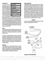 7
7
-
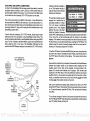 8
8
-
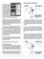 9
9
-
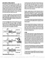 10
10
-
 11
11
-
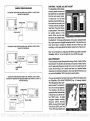 12
12
-
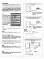 13
13
-
 14
14
-
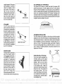 15
15
-
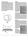 16
16
-
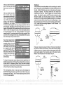 17
17
-
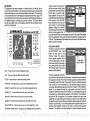 18
18
-
 19
19
-
 20
20
-
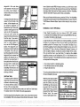 21
21
-
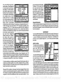 22
22
-
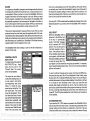 23
23
-
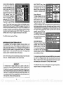 24
24
-
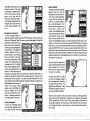 25
25
-
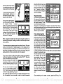 26
26
-
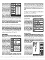 27
27
-
 28
28
-
 29
29
-
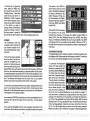 30
30
-
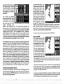 31
31
-
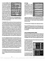 32
32
-
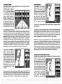 33
33
-
 34
34


Lowrance GlobalMap 1000 User manual
- Category
- Navigators
- Type
- User manual
Ask a question and I''ll find the answer in the document
Finding information in a document is now easier with AI
Related papers
-
Lowrance GlobalMap 3000MT User manual
-
-
Lowrance GlobalMap 6500C User manual
-
-
-
-
-
-
-
Other documents
-
Eagle ACCUNAV 2 Specification
-
Lowrance electronic GlobalMap 12 User manual
-
-
-
Furuno GP-36 User manual
-
-
-
-
-