
1
04/03 P/N 211657B
© COPYRIGHT 2002 by HUFFY SPORTS
Customer Service
N53 W24700 South Corporate Circle
Sussex, WI 53089
U.S.A.
A Huffy Company
WRITE IN YOUR MODEL NUMBER:
___________
REQUIRED TOOLS AND
MATERIALS:
• (Two) People
• Tape Measure
• Tape
• Wood Board (Scrap)
• Wrenches: (Two) 1/2”, 9/16”, 3/4”or (Two) Large
and Small Adjustable Wrenches (9/16” Deep
Socket w/Ext. Recommended)
• Garden Hose or Sand (420 lb.) (191 kg)
• 2 Gallons (7.6 Liters) of Non-Toxic Antifreeze
• Sawhorse or Support Table
• Two Step Ladders 8 ft. (2.4 m)
Portable Basketball System
Owners Manual
Toll-Free Customer Service Number for U.S: 1-800-558-5234 Canada Only: 1-800-284-8339
Internet Address: http://www.huffysports.com
In U.S. and Canada only: Have questions...don’t go back to the store!
We appreciate your purchasing one of our many fine products. We are sure that you will be very satisfied with your selection. Although
great care and effort have been taken, occasionally problems may occur. To ensure prompt and correct handling of any problems, or to
answer any questions, please contact our Toll-Free Customer Service Number listed below. Service will be quicker if you have your
Model Number (found on carton) and assembly instructions ready when calling. PLEASE WRITE YOUR MODEL NUMBER IN
THE SPACE PROVIDED ABOVE.
SAFETY INSTRUCTIONS
Most injuries are caused by misuse and/or not following instructions.
Use caution when using this system.
• If using a ladder during assembly, use extreme caution.
• Two (2) people are recommended for this operation.
• Check base regularly for leakage. Slow leaks could cause system to tip over
unexpectedly.
• Seat the pole sections properly (if applicable). Failure to do so could allow the pole
sections to separate during play and/or transport of the system.
• Climate, corrosion or misuse could result in system failure.
• Minimum operational height is 6' 6" (1.98 m) to the bottom of backboard.
• This equipment is intended for home recreational use only and NOT
excessive competitive play.
• Read and understand the warning label affixed to pole. Label is shown on page 2.
• The life of your basketball pole depends on many conditions. The climate,
placement of the pole, the location of the pole, exposure to corrosives such as
pesticides, herbicides or salts are all important.
• If technical assistance is required, contact Huffy Sports.
• Adult supervision is recommended when adjusting height.
FAILURE TO FOLLOW THESE SAFETY INSTRUCTIONS MAY RESULT IN
SERIOUS INJURY, PROPERTY DAMAGE AND WILL VOID WARRANTY.
Owner must ensure that all players know and follow these rules for safe
operation of the system.
To ensure safety, do not attempt to assemble this system without following the
instructions carefully. Proper and complete assembly, use and supervision is
essential for proper operation and to reduce the risk of accident or injury. A high
probability of serious injury exists if this system is not installed, maintained, and
operated properly. Check entire box and inside all packing material for parts
and/or additional instructional material. Before beginning assembly, read the
instructions and identify parts using the hardware identifier and parts list in this
document.
For more information on assembly, placement, proper use and maintenance, visit
The American Basketball Council website at http://www.smarthoops.com.

2
P/N 211657B 04/03
Crank
Height
Indicator
Hook
201254 2/99
1
2
4
3
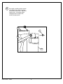
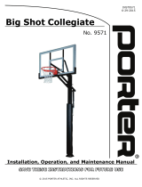
MOVING SYSTEM
1. Adjust basketball backboard
height to lowest position.
2. Rotate basketball system
forward, while holding pole,
until wheels engage with
ground.
3.
Move basketball system to
desired location.
4. Carefully rotate basketball
system upright.
5. Reattach ground restraint and
check system for stability.
HEIGHT ADJUSTMENT
TO ADJUST BACKBOARD:
Position looped end of crank
onto hook as shown. Rotate
crank handle to raise or lower
backboard.
30
WARNING
FAILURE TO FOLLOW THESE WARNINGS MAY RESULT
IN SERIOUS INJURY AND/OR PROPERTY DAMAGE.
Owner must ensure that all players know and follow
these rules for safe operation of the system.
• DO NOT HANG on the rim or any part of the system
including backboard, support braces or net.
• During play, especially when performing dunk type
activities, keep player's face away from the backboard, rim
and net. Serious injury could occur if teeth/face come in
contact with backboard, rim or net.
• Do not slide, climb, shake or play on base and/or pole.
• After assembly is complete, fill system completely with
water or sand and stake to the ground. Never leave system
in an upright position without filling base with weight, as
system may tip over causing injuries.
• When adjusting height or moving system, keep hands and
fingers away from moving parts.
• Do not allow children to move or adjust system.
• During play, do not wear jewelry (rings, watches, necklaces,
etc.). Objects may entangle in net.
• Surface beneath the base must be smooth and free of
gravel or other sharp objects. Punctures cause leakage and
could cause system to tip over.
• Keep organic material away from pole base. Grass, litter,
etc. could cause corrosion and/or deterioration.
• Check pole system for signs of corrosion (rust, pitting,
chipping) and repaint with exterior enamel paint. If rust has
penetrated through the steel anywhere, replace pole
immediately.
• Check system before each use for proper ballast, loose
hardware, excessive wear and signs corrosion and repair
before use.
•
Check system before each use for instability.
• Do not use system during windy and/or severe weather
conditions; system may tip over. Place system in the
storage position and/or in an area protected from the wind
and free from personal property and/or overhead wires.
• Never play on damaged equipment.
• See instruction manual for proper installation and
maintenance.
• When moving system, use caution to keep mechanism from
shifting.
• Keep pole top covered with cap at all times.
• Do not allow water in tank to freeze. During sub-freezing
weather add non-toxic antifreeze, sand or empty tank
completely and store. (Do not use salt.)
• Use extreme caution if placing system on sloped surface.
System may tip over more easily.
201241 2/99
In the U.S.:1-800-558-5234 and Canada: 1-800-284-8339

3
04/03 P/N 211657B
IMPORTANT! WRITE DOWN MODEL NUMBER FROM BOX ON PAGE 1 OF THIS OWNERS MANUAL
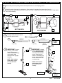
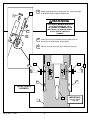
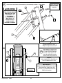
1.
Carefully, position front tank (1) upside down. Secure wheel (2) into place from bottom side (illust. A)
making sure the wheel bracket (5) seeds into base as in illust. B. Repeat procedure for opposite wheel. Finger tighten,
then upright assembly.
2.
Correctly identify each pole section
and mark tape as shown.
TOP
MIDDLE
BOTTOM
3.
5” (13 cm)
35-1/2”
(90.2 cm)
5” (13 cm)
Remove all parts from packing material and separate tanks from the shipping position.
8
7
9
LARGE
HOLE
LARGE
HOLE
BOTTOM VIEW
Wood Scrap
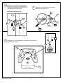
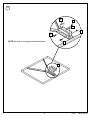
5.
4.
IMPORTANT! Bounce
pole top (7) and middle
section (8) together as
shown until they no longer
move toward taped
reference mark. Upright
assembly.
NOTE: Pole sections
should have a 3-3/4"
(9.5 cm) minimum
overlap.
7
8
IMPORTANT! Holes in
top (7) and bottom pole (9)
sections MUST ALIGN to
correctly position elevator
system toward playing
surface. Add bottom pole
section (9) to assembly as
shown and bounce until
completely tight.
NOTE: Pole sections
should have a 3-3/4"
(9.5 cm) minimum
overlap.
8
7
5
6
3
9
4
SIDE VIEW
5
6
2
3
1
BOTTOM VIEW
4
B
A

4
P/N 211657B 04/03
1
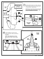
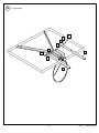
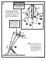
Install rod (15) through holes in bottom pole
section (9) and eyebolt (16).
7.
Set rear tank (17) onto front tank (1) and insert pole assembly into
tank assembly as shown.
8.
16
15
10
7
9
8
17
Spread collar (10) open and carefully raise
collar (10) to 35-1/2” (90.2 cm) taped mark.
Finger tighten hardware to prevent collar (10)
from moving and scratching pole.
NOTE: Avoid scratching pole.
6.
11
9
13
10
14
12
16
9
12

5
04/03 P/N 211657B
Loosen hardware on collar (10) and
secure struts (20) to collar (10) as shown
and tighten.
NOTE: Final adjustments to collar
may need to be made. Refer to Step
32.
10.
FRONT
VIEW
20
20
11
10
13
20
12
14
12
9.
Carefully position system on its side, and secure
bottom of pole to tank as shown, a deep socket
is recommended. Upright system.
NOTE: Keep unnecessary pressure off of the
pole assembly when in this position. Two
people recommended for this step.
BOTTOM
VIEW
12
1
9
18
17
IMPORTANT!
DO NOT
OVER TIGHTEN.
19
18
12
19

6
P/N 211657B 04/03
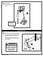
Once again, carefully position system
in the side position and secure strut
(20) to tank (1) as shown. Repeat for
opposite side. Completely tighten
including bolts from step 2 then
carefully upright system.
11.
11
13
20
1
12

7
04/03 P/N 211657B
MTT01.EPS
27
4
6
24
24
4
6
26
4
4
13.
Install left screw jack support plate (26) and right screw jack
support plate (27) to pole. Finger tighten.
ELEVATOR INSTALLATION
TWO PERSON MINIMUM REQUIRED
FOR THIS PROCEDURE. NOT
FOLLOWING RECOMMENDATION
MAY RESULT IN SERIOUS BODILY
INJURY AND/OR PROPERTY
DAMAGE.
WARNING
WARNING
(See Text Page)
SAWHORSE OR SUPPORT TABLE
Note
(See Text Page)

8
P/N 211657B 04/03
15.
16.
1
7
9
8
32
Center screw jack (29) between support plates (26 & 27)
and secure as shown below. Finger tighten.
Place cover over screw jack (29). Install pole cap (32).
28
29
33
26
7
27
4
4
33
IMPORTANT!
DO NOT OVER
TIGHTEN.
31
14.
Attach height decal (28) on screw jack (29). Align lower edge
of decal with bottom of black indicator tube.
4
4
6
6
29
FRONT VIEW OF
ASSEMBLY
TWO PERSON MINIMUM REQUIRED
FOR THIS PROCEDURE. NOT
FOLLOWING RECOMMENDATION
MAY RESULT IN SERIOUS BODILY
INJURY AND/OR PROPERTY
DAMAGE.
WARNING

9
04/03 P/N 211657B
37
NOTE: Be sure to use proper bracket as shown.
17.
36
36
35
35
19
19

10
P/N 211657B 04/03
40
4
4
38
38
39
39
37
6
Refer To Instructions
Included With Rim
Hardware For Rim
Assembly.
18.
Finger tighten.

11
04/03 P/N 211657B
4
4
38
38
40
39
37
6
39
20.
Finger tighten.

12
P/N 211657B 04/03
½
Secure board and elevator tube assembly to pole assembly as shown. Finger tighten.
IMPORTANT!
DO NOT OVER
TIGHTEN.
4
6
38
38
40
4
TWO PERSON MINIMUM
REQUIRED FOR THIS
PROCEDURE. NOT
FOLLOWING
RECOMMENDATION
MAY RESULT IN
SERIOUS BODILY
INJURY AND/OR
PROPERTY DAMAGE.
WARNING
Insert spacer (41) through top
holes of height indicator cover
(31) and screw jack assembly
as shown. Align spacer and
screw jack assembly between
elevator tubes (34) and secure.
IMPORTANT!
WHEN SECURING SCREW JACK (20) TO
TOP ELEVATOR TUBES (34), USE
SPACER (41) BETWEEN ELEVATOR
TUBES AS SHOWN.
NOTE:
NOW COMPLETELY TIGHTEN ALL
BOLTS FROM STEPS 13-22.
4
40
4
6
SCREW JACK
ASSEMBLY
21.
22.
SAWHORSE OR SUPPORT TABLE
41
25

13
04/03 P/N 211657B
MTT02.EPS
211307
Make final adjustments to level
the rim. If backboard and rim are
tipped back, raise collar (10) until
level and tighten. If backboard
and rim are tipped forward, lower
collar until level and tighten.
Maximum adjustment travel is 33”
to 37” (84-94 cm) from bottom of
pole to top of collar.
24.
10
23.
Roll assembly to desired playing area.
Secure assembly to ground using rope
(21) and tie down stake (22). Fill larger
tank (1) with water (approx. 24 gallons (91
liters)) or sand (approx. 300 lbs (136 kg))
and smaller tank (17) with (approx. 10
gallons (78.9 liters)) or sand (approx. 120
lbs (54.4 kg)) and snap fill caps (23) in
place.
22
23
21
WARNING
23
23
1
17
IMPORTANT!
Two Gallons (7.6 Liter) of
Non-Toxic Antifreeze
Required. Add one gallon
(3.8 liters) to each tank to
prevent freezing in sub-
freezing climates.
DO NOT LEAVE ASSEMBLY
UNATTENDED WHEN EMPTY,
IT MAY TIP OVER.

14
P/N 211657B 04/03
Position looped end of height adjustment crank
(34) onto hook as shown. Rotate crank handle
to raise or lower backboard. View label (28) to
determine approximate backboard height.
NOTE: If height adjustment is difficult to
operate, you may have over tightened the
areas indicated.
Height Adjustment
26.
HOOK
34
28
WARNING
STORE CRANK OUT OF REACH
OF CHILDREN. DO NOT ALLOW
CHILDREN TO ADJUST HEIGHT
WITHOUT ADULT SUPERVISION
COULD RESULT IN SERIOUS
BODILY HARM AND/OR
PROPERTY DAMAGE.
25.
10 feet
(3.05 m)
30
Apply height
adjustment label (30)
to front of pole as
shown.
Regulation Rim
Height is
10 feet (3.05 m).

15
04/03 P/N 211657B
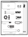
Item #3 (2)
Item #6 (13)
Item #15 (1)
Item #11 (4)
Item #4 (24)
* YOU MAY HAVE EXTRA PARTS WITH THIS MODEL.
HARDWARE IDENTIFIER (CONTINUED)
Item
Qty. Part No. Description
1 1 226350 Tank, (Front Section)
2 2 226403 Wheel
3 2 206245 Bolt, Hex Head, 1/2-13 x 5-1/2 Long
4 24 203474 Washer, 1/2 I.D., 1-5/64 O.D.
5 2 206341 Bracket, Wheel
6 13 206340 Locknut, Hex, 1/2-13
7 1 918812 Top Pole Section
8 1 990062 Middle Pole Section
9 1 908407 Bottom Pole Section
10 1 906343 Collar, Pole/Strut
11 4 203113 Bolt, Hex Head Flange,
5/16-18 x 2-1/2 Long
12 12 203232 Washer, Flat, 3/4 O.D.
13 10 203100 Nut, Hex Flange, 5/16-18
14 2 200516 Bolt Cover, Vinyl, (Black)
15 1 206347 Rod, Steel, 1/2 O.D. x 4-3/4 Long
16 1 206352 Eyebolt, 3/8 x 6 Long
17 1 226351 Tank, (Rear Section)
18 1 206346 Washer, Rectangle, 1-7/8 x 4
19 3 201124 Locknut, Hex 3/8-16
20 2 906410 Strut, 1-1/4 O.D. x 43
Item
Qty. Part No. Description
21 1 202438 Black Nylon Rope
22 1 203124 Stake, Tie Down
23 3 206219 Fill Cap
24 2 206273 Bolt, Hex Head, 1/2-13 x 4-1/2 Long
25 4 201651 Spacer
26 1 906277 Plate, Jack Support, (Left)
27 1 906276 Plate, Jack Support, (Right)
28 1 205229 Label, Height Indicator
29 1 805231 Screw Jack
30 1 201254 Label, Height Adjustment & Moving
31 1 206234 Cover, Height Indicator
32 1 206913 Cap, Pole, 3-1/2 Round
33 2 206249 Bolt, Hex Flange, 1/2-13 x 1-1/4
34 1 806259 Crank, Height Adjustment
35 2 206360 Bolt, Hex Head 3/8-16 x 2.625 Long
36 2 200874 Spacer
37 1 900964 Board Bracket
38 4 904807 Tube, 25.5 x 1.5, 4 Holes
39 4 202862 Spacer, Black Plastic, 1.19” Long
40 5 206244 Bolt Hex Head, 1/2-13 x 8, Zinc Plated
41 1 206269 Spacer, 4 Long x .500 ID x .750 OD
Item #13 (10)
Item #12 (12)
Item #14 (2)
* You may have extra parts with this model.
HARDWARE IDENTIFIER
PARTS LIST

16
P/N 211657B 04/03
Item #41 (1)
Item #40 (5)
Item #39 (4)
Item #24 (2)
Item #19 (3)
Item #35 (2)
Item #18 (1)
Item #33 (2)
Item #36 (2)
HARDWARE IDENTIFIER (CONTINUED)
HARDWARE IDENTIFIER
* YOU MAY HAVE EXTRA PARTS WITH THIS MODEL.
Item #25 (4)
-
 1
1
-
 2
2
-
 3
3
-
 4
4
-
 5
5
-
 6
6
-
 7
7
-
 8
8
-
 9
9
-
 10
10
-
 11
11
-
 12
12
-
 13
13
-
 14
14
-
 15
15
-
 16
16


Huffy RC2000MK2 User manual
- Type
- User manual
Ask a question and I''ll find the answer in the document
Finding information in a document is now easier with AI
Related papers
Other documents
-
American DJ LTS-2 User manual
-
Spalding M4115221 User manual
-
-
-
-
-
-
-
 Porter BIG SHOT COLLEGIATE PACKAGE Operating instructions
-
 Porter BIG SHOT PRO PACKAGE Operating instructions

