Tripp Lite SmartOnline 120/208V is an intelligent UPS (uninterruptible power supply) system designed to protect critical electronic equipment from power problems, including blackouts, brownouts, surges, and line noise. It provides continuous power to connected devices during power outages, ensuring that they can operate without interruption. The SmartOnline 120/208V features a true online design, which means that it constantly monitors and regulates the incoming power, providing the highest level of protection for sensitive electronic equipment.
Tripp Lite SmartOnline 120/208V is an intelligent UPS (uninterruptible power supply) system designed to protect critical electronic equipment from power problems, including blackouts, brownouts, surges, and line noise. It provides continuous power to connected devices during power outages, ensuring that they can operate without interruption. The SmartOnline 120/208V features a true online design, which means that it constantly monitors and regulates the incoming power, providing the highest level of protection for sensitive electronic equipment.


-
 1
1
-
 2
2
-
 3
3
-
 4
4
-
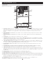 5
5
-
 6
6
-
 7
7
-
 8
8
-
 9
9
-
 10
10
-
 11
11
-
 12
12
-
 13
13
-
 14
14
-
 15
15
-
 16
16
-
 17
17
-
 18
18


Tripp Lite 120/208V User manual
- Type
- User manual
- This manual is also suitable for
Tripp Lite SmartOnline 120/208V is an intelligent UPS (uninterruptible power supply) system designed to protect critical electronic equipment from power problems, including blackouts, brownouts, surges, and line noise. It provides continuous power to connected devices during power outages, ensuring that they can operate without interruption. The SmartOnline 120/208V features a true online design, which means that it constantly monitors and regulates the incoming power, providing the highest level of protection for sensitive electronic equipment.
Ask a question and I''ll find the answer in the document
Finding information in a document is now easier with AI
Related papers
-
Tripp Lite 20kVA User manual
-
Tripp Lite SmartOnline 3-Phase 20kVA & 30kVA UPS Owner's manual
-
-
-
Tripp Lite 5kVA User manual
-
-
-
-
-
Other documents
-
Epcom EPU500L User manual
-
BlueWalker BlueW PowerWalker Remote Panel User manual
-
Toshiba Power Supply 1700 User manual
-
Minuteman Endeavor User manual
-
Intermec 751G Operating instructions
-
Eaton Powerware 9120 User manual
-
EG4 ELECTRONICS 100A 48VDC User manual
-
Falcon SUP1.0K-1C User manual
-
-
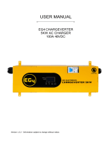 EG4 ELECTRONICS 48VDC 5KW AC Charger User manual
