Page is loading ...

May 2010
VAV-SVP01A-EN
Installation
Operation
Programming
VAV VV550 LonTalk
Controller

© 2010 Trane All rights reserved VAV-SVP01A-EN
Warnings, Cautions and Notices
Warnings, Cautions and Notices. Note that warnings, cautions and notices appear at
appropriate intervals throughout this manual. Warnings are provided to alert installing contractors
to potential hazards that could result in personal injury or death. Cautions are designed to alert
personnel to hazardous situations that could result in personal injury, while notices indicate a
situation that could result in equipment or property-damage-only accidents.
Your personal safety and the proper operation of this machine depend upon the strict observance
of these precautions.
WARNING
This equipment is to be serviced/installed by qualified personnel ONLY. Under NO
circumstances should an unqualified person service/install it. Servicing/installing this
equipment is a job requiring specific knowledge and MUST be left to a professional. It involves
working with hazardous components that are potentially life threatening if not handled
properly. Improperly installed, adjusted or altered equipment by an unqualified person could
result in death or serious injury.
WARNING
Personal Protective Equipment (PPE) Required!
Installing/servicing this unit could result in exposure to electrical, mechanical and chemical
hazards.
• Before installing/servicing this unit, technicians MUST put on all Personal Protective
Equipment (PPE) recommended for the work being undertaken. ALWAYS refer to appropriate
MSDS sheets and OSHA guidelines for proper PPE.
• When working with or around hazardous chemicals, ALWAYS refer to the appropriate MSDS
sheets and OSHA guidelines for information on allowable personal exposure levels, proper
respiratory protection and handling recommendations.
• If there is a risk of arc or flash, technicians MUST put on all necessary Personal Protective
Equipment (PPE) in accordance with NFPA70E for arc/flash protection PRIOR to servicing the
unit.
Failure to follow recommendations could result in death or serious injury.
ATTENTION: Warnings, Cautions and Notices appear at appropriate sections throughout
this literature. Read these carefully.
WARNING: Indicates a potentially hazardous situation which, if not avoided, could
result in death or serious injury.
CAUTION: Indicates a potentially hazardous situation which, if not avoided, could
result in minor or moderate injury. It could also be used to alert against unsafe practices.
NOTICE: Indicates a situation that could result in equipment or property-damage-only
accidents.

VAV-SVP01A-EN 3
Warnings, Cautions and Notices
WARNING
Electrocution and Fire Hazards with Improperly Installed and Grounded
Field Wiring!
Improperly installed and grounded field wiring poses FIRE & ELECTROCUTION hazards. To avoid
these hazards, you MUST follow requirements for field wiring installation and grounding as
described in NEC and your local/state electrical codes. All field wiring MUST be performed by
qualified personnel. Failure to follow these requirements could result in death or serious injury.
Overview of Manual
Note: One copy of this document ships inside the control panel of each unit and is customer
property. It must be retained by the unit's maintenance personnel.
This booklet describes proper installation, operation, and maintenance procedures for delivered
air systems. By carefully reviewing the information within this manual and following the
instructions, the risk of improper operation and/or component damage will be minimized. It is
important that periodic maintenance be performed to help assure trouble free operation. A
maintenance schedule is provided at the end of this manual. Should equipment failure occur,
contact a qualified service organization with qualified, experienced HVAC technicians to properly
diagnose and repair this equipment.

4 VAV-SVP01A-EN
Table of Contents
General Information . . . . . . . . . . . . . . . . . . . . . . . . . . . . . . . . . . . . . . . . . . . . . . . . . . . . 6
Chapter Overview . . . . . . . . . . . . . . . . . . . . . . . . . . . . . . . . . . . . . . . . . . . . . . . . . . 6
Unit Control Module VAV VV550 Controller . . . . . . . . . . . . . . . . . . . . . . . . . . . 6
Specifications . . . . . . . . . . . . . . . . . . . . . . . . . . . . . . . . . . . . . . . . . . . . . . . . . . . . . 7
VV550 Enhancements . . . . . . . . . . . . . . . . . . . . . . . . . . . . . . . . . . . . . . . . . . . . . . 8
VV550 Features . . . . . . . . . . . . . . . . . . . . . . . . . . . . . . . . . . . . . . . . . . . . . . . . . . . . 9
Shipping & Storage . . . . . . . . . . . . . . . . . . . . . . . . . . . . . . . . . . . . . . . . . . . . . . . 11
Data Lists . . . . . . . . . . . . . . . . . . . . . . . . . . . . . . . . . . . . . . . . . . . . . . . . . . . . . . . . 12
VAV Start Up/Check Out Procedure . . . . . . . . . . . . . . . . . . . . . . . . . . . . . . . . . . . . . . 14
Chapter Overview . . . . . . . . . . . . . . . . . . . . . . . . . . . . . . . . . . . . . . . . . . . . . . . . . 14
VV550 Pre-Power Check-Out . . . . . . . . . . . . . . . . . . . . . . . . . . . . . . . . . . . . . . . . 14
VV550 Power Wiring . . . . . . . . . . . . . . . . . . . . . . . . . . . . . . . . . . . . . . . . . . . . . . 15
Light Emitting Diode (LED) Operations . . . . . . . . . . . . . . . . . . . . . . . . . . . . . . . 16
Communication Wiring . . . . . . . . . . . . . . . . . . . . . . . . . . . . . . . . . . . . . . . . . . . . 19
Wireless Zone Sensor . . . . . . . . . . . . . . . . . . . . . . . . . . . . . . . . . . . . . . . . . . . . . 27
VAV VV550 Controller Programming and Operation . . . . . . . . . . . . . . . . . . . . . . 42
Chapter Overview . . . . . . . . . . . . . . . . . . . . . . . . . . . . . . . . . . . . . . . . . . . . . . . . . 42
Accessing Rover/Comm5 LonTalk . . . . . . . . . . . . . . . . . . . . . . . . . . . . . . . . . . . 42
VV550 Controller Device Home Tabs: At a Glance . . . . . . . . . . . . . . . . . . . . . 44
Entering and Exiting the Service Mode . . . . . . . . . . . . . . . . . . . . . . . . . . . . . . 51
Overriding VAVs . . . . . . . . . . . . . . . . . . . . . . . . . . . . . . . . . . . . . . . . . . . . . . . . . . 51
VAV VV550 Controller Device Home Tabs: Instructions . . . . . . . . . . . . . . . . . . . . 54
Chapter Overview . . . . . . . . . . . . . . . . . . . . . . . . . . . . . . . . . . . . . . . . . . . . . . . . . 54
Configuration . . . . . . . . . . . . . . . . . . . . . . . . . . . . . . . . . . . . . . . . . . . . . . . . . . . . 54
Setpoints Tab . . . . . . . . . . . . . . . . . . . . . . . . . . . . . . . . . . . . . . . . . . . . . . . . . . . . 54
Unit Tab . . . . . . . . . . . . . . . . . . . . . . . . . . . . . . . . . . . . . . . . . . . . . . . . . . . . . . . . . 57
Setup Tab . . . . . . . . . . . . . . . . . . . . . . . . . . . . . . . . . . . . . . . . . . . . . . . . . . . . . . . . 59
Inputs Tab . . . . . . . . . . . . . . . . . . . . . . . . . . . . . . . . . . . . . . . . . . . . . . . . . . . . . . . 61
Outputs Tab . . . . . . . . . . . . . . . . . . . . . . . . . . . . . . . . . . . . . . . . . . . . . . . . . . . . . . 63
Test Tab . . . . . . . . . . . . . . . . . . . . . . . . . . . . . . . . . . . . . . . . . . . . . . . . . . . . . . . . . 64
Other Tab . . . . . . . . . . . . . . . . . . . . . . . . . . . . . . . . . . . . . . . . . . . . . . . . . . . . . . . . 65
Overrides . . . . . . . . . . . . . . . . . . . . . . . . . . . . . . . . . . . . . . . . . . . . . . . . . . . . . . . . 66
Sequence of Operations . . . . . . . . . . . . . . . . . . . . . . . . . . . . . . . . . . . . . . . . . . . . . . . . 67
Chapter Overview . . . . . . . . . . . . . . . . . . . . . . . . . . . . . . . . . . . . . . . . . . . . . . . . . 67
Calibration . . . . . . . . . . . . . . . . . . . . . . . . . . . . . . . . . . . . . . . . . . . . . . . . . . . . . . . 67

VAV-SVP01A-EN 5
Occupancy Modes . . . . . . . . . . . . . . . . . . . . . . . . . . . . . . . . . . . . . . . . . . . . . . . . 68
Space Temperature Control: Single Duct Units . . . . . . . . . . . . . . . . . . . . . . . . 69
Space Temperature Control: Fan-Powered Units . . . . . . . . . . . . . . . . . . . . . . 72
Ventilation Flow Control . . . . . . . . . . . . . . . . . . . . . . . . . . . . . . . . . . . . . . . . . . . 74
Flow Tracking . . . . . . . . . . . . . . . . . . . . . . . . . . . . . . . . . . . . . . . . . . . . . . . . . . . . 76
Air and Water Balancing . . . . . . . . . . . . . . . . . . . . . . . . . . . . . . . . . . . . . . . . . . . . . . . 78
Chapter Overview . . . . . . . . . . . . . . . . . . . . . . . . . . . . . . . . . . . . . . . . . . . . . . . . . 78
Air Balancing . . . . . . . . . . . . . . . . . . . . . . . . . . . . . . . . . . . . . . . . . . . . . . . . . . . . . 78
Rover Air and Water Balancing Tool . . . . . . . . . . . . . . . . . . . . . . . . . . . . . . . . . 79
Troubleshooting . . . . . . . . . . . . . . . . . . . . . . . . . . . . . . . . . . . . . . . . . . . . . . . . . . . . . . . 83
Chapter Overview . . . . . . . . . . . . . . . . . . . . . . . . . . . . . . . . . . . . . . . . . . . . . . . . . 83
Diagnosing the Problem . . . . . . . . . . . . . . . . . . . . . . . . . . . . . . . . . . . . . . . . . . . 83
Troubleshooting Procedures . . . . . . . . . . . . . . . . . . . . . . . . . . . . . . . . . . . . . . . 87
Trane/Honeywell Proportional Valve Check Out Procedures . . . . . . . . . . . 105

6 VAV-SVP01A-EN
General Information
Chapter Overview
This chapter contains information about the following:
• Unit Control Module VAV VV550 Controller
• Specifications
• VAV VV550 Controller Enhancements
• VAV VV550 Controller Features
• Shipping & Storage
• Data Lists
Unit Control Module VAV VV550 Controller
The VV550 is a microprocessor-based, Direct Digital Controller (DDC) for the (Variable Air Volume)
VAV terminal unit. Units have been made with either pneumatic, analog electronic, or
microprocessor controls (DDC VAV). This manual discusses only terminal units with Comm 5 VAV
VV550 DDC Controller. Factory installed DDC/VAV controls are available with all single duct
terminal units, dual duct units, as well as parallel fan-powered and series fan-powered units. Two
VAV VV550 Controllers are required for dual duct units (one for the heating duct and one for the
cooling duct) and another application requiring to controllers is Flow tracking (one unit controller
is programmed from the factory with the Space temperature program and the other is downloaded
with the Flow tracking program.
The VAV VV550 Controller can be configured from the factory with three different application
programs. The VAV VV550 Controller programmed for space temperature control modulates a
VAV's damper blade based on a zone temperature, measured airflow, and set points to
continuously control conditioned air delivery to the space. The volume of incoming air is
monitored and the damper adjusts to provide accurate control independent of the duct pressure.
The damper modulates between operator set points depending on space conditions. Additionally,
fan and heat outputs may be energized depending on the application.
The VAV VV550 Controller programmed for ventilation flow control is applied to a VAV terminal and
used to temper cold outdoor air (OA) that is brought into a building for ventilation purposes. The
tempered air is intended to supply an air-handling unit (AHU), which provides comfort control to
the zones it is serving. The VAV terminal supplies the correct amount of ventilation air and, when
reheat is added, tempers the ventilation air to reduce the load on the air handler by sensing the
discharge air temperature of VAV unit.
The VAV VV550 Controller programmed for Flow Tracking Control (FTC) has two VAV VV550
Controllers working together to provide flow tracking control. One VAV VV550 controller is
programmed from the factory with the Space temperature program and the other is downloaded
with the Flow tracking program. The space temperature controller airflow output is bound to the
flow tracking controller airflow setpoint input. The flow tracking controller adds the configured
airflow tracking offset (positive or negative) to the airflow setpoint (communicated airflow setpoint)
and controls the airflow to this setpoint.
The VAV VV550 Controller utilizes an FTT-10A Free Topology transceiver, which supports non-
polarity sensitive, free topology wiring, which allows the system installer to utilize star, bus, and
loop architectures. Available inputs include a twisted/shielded communication link, zone sensor,
auxiliary temperature sensor (optional), and Occupy/Unoccupied Sensor (optional), and 24VAC
power.

VAV-SVP01A-EN 7
General Information
Specifications
Power Requirements
The UCM VV550 requires 18-32 Vac (24VAC nominal), 50/60 Hz, and up to 50 VA, depending on the
number of heat outputs (stages), which consume 10 VA each.
Operating Environments - VAV VV550 Controller
32° to 140°F (0° to 60°C), 5% to 90% relative humidity, non-condensing
Storage Environments - VAV VV550 Controller
-40° to 185°F (-40° to 85°C), 5% to 90% relative humidity, non-condensing
From 5 to 95% non-condensing
Relative humidity:
From 5 to 95% non-condensing
Analog Inputs
Space temperature; thermistor: 10 kΩ@ 77°F (25°C) From 14 to 122°F (-10 to 50°C)
Space setpoint; potentiometer: 1 kΩ From 50 to 90°F (-10 to 32.2°C)
Primary/discharge air temperature; thermistor: 10 kΩ@ 77°F (25°C) From -40 to 212°F (-40 to 100°C)
Primary air flow; pressure transducer: From 0 to 2 in. water (0 to 498 Pa)
Binary Input
Occupancy or generic (dry contact)
Binary Outputs
Air valve close: maximum output rating: 12 VA
Air valve open: maximum output rating: 12 VA
Heat stage 1: maximum output rating: 12 VA
Heat stage 2: maximum output rating: 12 VA
Heat stage 3/Fan on/off: maximum output rating: 12 VA
Agency Listings/Compliance
VAV VV550 Controller:
UL 873 and CSA C22.2 No. 24-93:
Temperature Indicating and Regulating
Equipment
VAV VV551 Controller:
UL-916-PAZX-energy management
CUL-C22.2-signal devices-Canada
UL 94-5V (UL flammability rating for plenum use)
FCC Part 15, Class A
CE marked
Mounting
Typically, the VAV VV550 Controller is factory installed. However, the VAV VV550 Controller is
available with retrofit kits, in which case it must be field installed, and it’s named VV551.
Tracer Summit and VV550 Communications Link Wiring
Use 22 AWG Level 4 unshielded communication wire for most Comm5 installations. Limit Comm5
links to 4,500 ft and 60 devices maximum (without a repeater). Use one repeater for an additional
4,500 ft, 60 devices, and 8 communication stubs. Refer to Chapters 2 and 3 for further information
about wire selection.

8 VAV-SVP01A-EN
General Information
VV550 Enhancements
Controller Interface Flexibility
VV550 controller allows VAV units to communicate on a Trane Comm5 or LonTalk. This controller
works in standalone mode, peer-to-peer with one or more other units, or when connected to a Trane
Tracer Summit or a 3rd party building automation system that supports LonTalk.
Manual Test Function
The VV550 controller includes a manual test button that allows the field technician to manually
exercise the outputs of the controller. This feature is simple enough for the electrician to use to
check valve operation. Though this feature is standard on other Comm5 controllers, the feature is
not available on the VAV VV550 Controller.
Flow Tracking
The VV550 controller has been designed with the ability to be applied in flow tracking applications.
This allows the controller to pair with one of its peers to mirror the flow if that lead box, with or
without an offset (positive or negative static pressure as desired).
Ventilation Flow Control w/ Tempering
The VV550 controller has been designed with the ability to be applied in ventilation flow control
applications. These applications pair a fresh air unit with ventilation boxes to provide fresh
(tempered) air to a floor/area. This feature also includes a freeze protection sequence to protect the
hot water reheat coil from low supply air temperatures.
Auto-commissioning Sequence
The VV550 controller has been designed with an auto-commissioning sequence. With a discharge
air temperature sensor, this feature exercises the air valve, fan, and heat in the box and records the
temperature before and after the action. This allows the installer to more easily checkout the
operation of the box and commission by exception.
Automatic Calibration
The VV550 controller has been designed to automatically calibrate the flow transducer each time
the box transitions to unoccupied. This eliminates the need to initiate/schedule calibration for most
installations. The exception is 24/7 sites, in which case Tracer Summit can be used to initiate/
schedule calibration.
Temporary Heat (Construction Mode)
Upon reset (and power-up) if the controller does not detect a valid space temperature the controller
will provide temporary heat by driving the air valve to the heating maximum position. Of course,
the box will only provide heat if hot air is being provided by the air-handling unit.
Local versus Remote Reheat Flexibility
The controller can be configured to have local and/or remote heat. Plus, configuration flexibility is
offered that allows the installer to select whether local or remote heat has priority.
Zone Sensor Air Balancing
When applied with a Trane zone sensor module that includes a setpoint thumbwheel and ON and
CANCEL buttons, the controller offers a zone sensor air-balancing feature. This feature allows the
balancing contractor to drive the box to either its minimum or maximum flow setting by turning
the setpoint thumbwheel on the zone sensor module. Then, the balancing contractor can calibrate
the flow reading by pressing the ON (adjusts the reading upwards) or CANCEL (adjusts the reading
downwards) buttons on the zone sensor module.

VAV-SVP01A-EN 9
General Information
Flash Download
The VAV controller has been designed with flash memory. This allows us the option of upgrading
the controller in the field (features, corrections to defects) without changing out the controller.
Air/Water Balancing Application
An air/water balancing application is available in Rover that simplifies the startup, checkout and
balancing of VAV systems. This application is specifically designed for the balancing contractor.
Service Pin from the Trane Zone Sensor
Several Comm5 installation and commissioning scenarios have the technician pressing the
"service" button on the controller. By doing so, a service pin message is broadcast and received by
either the Rover service tool or by Tracer Summit (depending on the scenario). Because access to
the service button on the controller is often difficult, functionality has been included in the
controller that allows the technician to press and hold the ON button on the zone sensor to replicate
a service button press.
Trane Controller Compatibility
The VV550 is a Comm5 controller. As such, the controller is compatible with the latest generation
of Trane controls. This allows the VV550 controller to exist on the same communication wire as the
rest of our Comm5 controllers and share data with them as required. Additional inputs and outputs
can easily be added to the same communication link (Tracer MP503) for any required auxiliary
functions. In the past the cost of adding additional inputs and outputs (Comm4 link by way of a
UPCM) was much less cost-effective.
Drive Min and Max from Zone Sensor
When applied with a Trane zone sensor module that includes a thumbwheel setpoint, the VV550
controller can easily be overridden to minimum and maximum flow. By simply turning the
thumbwheel to "*" (end of range in one direction) the controller drives the air valve to the minimum
cooling flow setpoint. Similarly, turning the thumbwheel to the and "**" (end of range in the other
direction) the controller drives the air valve to the maximum cooling flow setpoint.
VV550 Features
Auto-commissioning Report (Tracer Summit)
Tracer Summit v15 and greater includes an auto-commissioning report that extracts and formats
the commissioning data for each VAV controller. This commissioning report is valuable both for the
installer and for the owner. The feature enables the system to be commissioned by exception -- a
benefit for the installer. The feature also can be used as validation -- valuable to the owner.
Simpler VAS
Tracer Summit v15 includes a new VAV Air System (VAS) specifically designed for Comm5
controllers. This new VAS was designed to be much simpler to understand and setup compared
to the existing (Comm3/4) VAS.
Static Pressure Optimization
As a part of the standard application, VAS calculates the duct static pressure setpoint based on the
most open VAV box. Until Tracer Summit v15, this feature was provided by way of field custom
programming.
Ventilation Optimization
As a part of the standard application, the VAV system has the ability to calculate the ventilation
setpoint for the air-handling unit. In addition, the VV550 controller has a ventilation ratio limit
feature that automatically increases airflow to maintain the required ventilation while operating

10 VAV-SVP01A-EN
General Information
within system limits for outside air percent concentrations in the supply air stream. Until Tracer
Summit v15, this feature was provided by way of field custom programming.
CO
2
Based Demand Control Ventilation
As a part of the standard application, the VAV system has the ability to calculate the ventilation
setpoint for the air-handling unit based on the CO
2
in one or more spaces. Until Tracer Summit v15,
this feature was provided by way of field custom programming. Plus, functionality was added to
the VV550 controller to support this feature (as standard). Providing the equivalent functionality
with the current VAV controller would require lots of custom programming.
Ventilation Flexibility
Ventilation can be managed in the following ways:
• Fixed occupancy ventilation setpoint
• Scheduled (or otherwise calculated) ventilation setpoint
• Occupancy sensor to switch between normal and reduced ventilation
•CO
2
sensor for demand-controlled ventilation
Note: CO
2
sensor input not available on VV550.
Temperature Statistics
As a part of the standard application, VAS calculates the minimum space temperature (and source),
maximum space temperature (and source), and the average space temperature. Until Tracer
Summit v15, this feature was provided by way of field custom programming.
VAV VV550 Controller Compatibility
The VAV VV550 Controller is designed with LonWorks technology and will be LonMark certified.
VV550 controller allows VAV units to communicate on a Trane Comm5 or LonTalk link. This
controller works in standalone mode, peer-to-peer with one or more other units, or when
connected to a Trane Tracer Summit or a 3rd party building automation system that supports
LonTalk. The Space Comfort Controller (SCC) is the profile assigned to the VV550 controller.
VAV VV550 Controller Outputs
VAV VV550 Controller Triac outputs for controlling a fan or reheat are rated at 12 VA each.
Wiring Diagram
Figure 2, p. 17 shows a typical wiring diagram for the redesigned VAV VV550 hardware. The new
service part number is BRD2960.

VAV-SVP01A-EN 11
General Information
Shipping & Storage
Each VAV product and its service literature are shipped in the same package. When unpacking,
make sure that the literature is not lost or discarded with the packing material. Visually inspect the
individual components for obvious defects or damage. All components are thoroughly inspected
before leaving the factory. Any claims for damage incurred during shipment must be filed with the
carrier.
When any component of the VAV system and/or field installed accessories must be stored for a
period of time prior to being installed, they must be protected from the elements. The storage
location temperature should be between -40° to 150°F (-40° to 65.6°C) and the relative humidity
should be 10% to 90%, non-condensing. The warranty will not cover damage to the VAV system or
controls due to negligence during storage. A controlled indoor environment must be used for
storage.
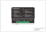
Figure 1. VV550 board layout
VAV VV550 controller and VAV 4.2 controller comparisons
VAV VV550 VAV 4.2
Supports Comm5 Supports only Comm4 or Comm3 (VariTrac or VariTrane)
No local CO2 sensor input. Uses only a communicated value Local CO2 sensor input is available.
Single star (*) initiates cool minimum airflow override.
Single star (*) initiates maximum flow override after pressing the ON
button. Override is held until you move the thumbwheel.
Double star (**) initiates cool maximum airflow override.
Double star (**) initiates unoccupied override after pressing the ON
button. Override is held until you move the thumbwheel.
Does not support VariTrac central control panel (CCP2 and CCP3). Does not support VariTrac CCP2 and CCP3.
Supports ventilation flow control Does not support ventilation flow control.
Supports flow tracking control. Does not support flow tracking control.
Supports enhanced ventilation control sequences. Does not support enhanced ventilation control sequence.
Supports auto-commissioning sequence. Does not support auto-commissioning sequence.
Supports zone sensor air balance sequences. Does not support zone sensor air balance sequence.

12 VAV-SVP01A-EN
General Information
Data Lists
If you’re going to connect to a generic building automation system, use Table 1, p. 12 and Tab le 2,
p. 13 for your points list.
Table 1. Input/output listing
Input Description Input SNVT type Output description Output SNVT type
Space temperature nviSpaceTemp SNVT_temp_p Space temperature nvoSpaceTemp SNVT_temp_p
Setpoint nviSetpoint SNVT_temp_p Unit status, mode nvoUnitStatus SNVT_hvac_status
Occupancy, schedule nviOccSchedule SNVT_tod_event Effective setpoint nvoEffectSetpt SNVT_temp_p
Occupancy, manual
command
nviOccManCmd SNVT_occupancy Effective occupancy nvoEffectOccup SNVT_occupancy
Occupancy sensor nviOccSensor SNVT_occupancy Heat cool mode nvoHeatCool SNVT_hvac_mode
Application mode nviApplicMode SNVT_hvac_mode Setpoint nvoSetpoint SNVT_temp_p
Heat/cool mode input nviHeatCool SNVT_hvac_mode
Discharge air
temperature
nvoDischAirTemp SNVT_temp_p
Fan speed command nviFanSpeedCmd SNVT_switch Terminal load nvoTerminalLoad SNVT_lev_percent
Auxiliary heat enable nviAuxHeatEnable SNVT_switch Space CO
2
nvoSpaceCO2 SNVT_ppm
Valve override nviValveOverride SNVT_hvac_overid
Effective air flow
setpoint
nvoEffectFlowSP SNVT_flow
Flow override nviFlowOverride SNVT_hvac_overid Air flow nvoAirFlow SNVT_flow
Emergency override nviEmergOverride SNVT_hvac_emerg File table address nvoFileDirectory
(a)
SNVT_address
Source temperature nviSourceTemp SNVT_temp_p Object status nvoStatus
(a)
SNVT_obj_status
Space CO
2
nviSpaceCO
2
SNVT_ppm Alarm message nvoAlarmMessage SNVT_str_asc
Clear alarms/
diagnostics
nviRequest
(a)
SNVT_obj_request
Air flow setpoint input nviAirFlowSetpt SNVT_flow
Ventilation ratio limit nviVentRatioLim SNVT_lev_percent
Ventilation for the zone
input
nviVentSetpt SNVT_flow
(a) Part of the node object.

VAV-SVP01A-EN 13
General Information
Table 2. Configuration properties
Configuration property
description Configuration property SNVT type SCPT reference
Send heartbeat nciSndHrtBt SNVT_time_sec SCPTmaxSendTime (49)
Occ temperature setpoints nciSetpoints SNVT_temp_setpt SCPTsetPnts (60)
Minimum send time nciMinOutTm SNVT_time_sec SCPTminSendTime (52)
Receive heartbeat nciRecHrtBt SNVT_time_sec SCPTmaxRcvTime (48)
Location label nciLocation SNVT_str_asc SCPTlocation (17)
Local bypass time nciBypassTime SNVT_time_min SCPTbypassTime (34)
Manual override time nciManualTime SNVT_time_min SCPTmanOverTime (35)
Space CO
2
limit nciSpaceCO2Lim SNVT_ppm SCPTlimitCO2 (42)
Nominal air flow nciNomFlow SNVT_flow SCPTnomAirFlow (57)
Air flow measurement gain nciFlowGain SNVT_multiplier SCPTsensConstVAV (67)
Minimum air flow nciMinFlow SNVT_flow SCPTminFlow (54)
Maximum air flow nciMaxFlow SNVT_flow SCPTmaxFlow (51)
Minimum air flow for heat nciMinFlowHeat SNVT_flow SCPTminFlowHeat (55)
Maximum air flow for heat nciMaxFlowHeat SNVT_flow SCPTmaxFlowHeat (37)
Minimum flow for standby nciMinFlowStdby SNVT_flow SCPTminFlowStby (56)
Firmware major version nciDevMajVer
(a)
n/a SCPTdevMajVer (165)
Firmware minor version nciDevMinVer
(a)
n/a SCPTdevMinVer (166)
Flow offset for tracking applications nciFlowOffset SNVT_flow_f SCPToffsetFlow (265)
Local heating minimum air flow nciMinFlowUnitHt SNVT_flow SCPTminFlowUnitHeat (270)
(a) Part of the node object

14 VAV-SVP01A-EN
VAV Start Up/Check Out Procedure
Chapter Overview
This chapter contains information about the following:
• VV550 Pre-Power Check-Out
• Power Wiring Requirements
• Light Emitting Diode (LED) Operations
• Communication Wiring
• Space Temperature Controller Analog Inputs
• Zone Sensor Wiring
• Auxiliary Sensor Wiring
• Binary Input Wiring
• Binary Output Wiring
• Ventilation Flow Control
• Auxiliary Sensor Wiring
• Flow Tracking Control
• Wireless Zone Sensor
VV550 Pre-Power Check-Out
WARNING
Live Electrical Components!
During installation, testing, servicing and troubleshooting of this product, it may be necessary to
work with live electrical components. Have a qualified licensed electrician or other individual who
has been properly trained in handling live electrical components perform these tasks. Failure to
follow all electrical safety precautions when exposed to live electrical components could result in
death or serious injury.
• Check the supply voltage at TB1. Proper polarity must be maintained. TB1-1 is the hot side (+)
and TB1-2 is the ground side (-) of the 24VAC input. Refer to Figure 2, p. 17 and Figure 3, p. 18
for the VAV VV550 Controller terminal locations. The VAV VV550 Controller cannot be powered
from a common 24VAC transformer that is supplying power to a device containing a full-wave
rectifier bridge in its power supply. The acceptable voltage is 18 to 32 VAC (24VAC cataloged).
However, voltages at either extreme may result in increased system instability.
• Verify that communications wiring has properly been terminated at TB2-1 (+) and TB2-2 (-).
Polarity is not important on the communications link.
• Verify that the zone sensor connections are correct as detailed in this IOP.
• If heat has been added to unit, verify that the proper output connections have been made as
detailed in this IOP.
• Verify that the tubing is properly connected to the transducer.

VAV-SVP01A-EN 15
VAV Start Up/Check Out Procedure
VV550 Power Wiring
Power Requirements
WARNING
Hazardous Voltage!
Disconnect all electric power, including remote disconnects before servicing. Follow proper
lockout/tagout procedures to ensure the power can not be inadvertently energized. Failure to
disconnect power before servicing could result in death or serious injury.
WARNING
Electrocution and Fire Hazards with Improperly Installed and Grounded
Field Wiring!
Improperly installed and grounded field wiring poses FIRE & ELECTROCUTION hazards. To avoid
these hazards, you MUST follow requirements for field wiring installation and grounding as
described in the National Electrical Codes (NEC) and your local/state electrical codes. All field
wiring MUST be performed by qualified personnel. Failure to follow these requirements could
result in death or serious injury.
Notice:
Use Copper Conductors Only!
Unit terminals are not designed to accept other types of conductors. Failure to use copper
conductors could result in equipment damage.
Use at least 16 AWG for power wiring and connect to terminal TB1-1 (+) and TB1-2 (-). 24VAC is
required to power the VAV VV550 Controller and has an acceptable voltage tolerance of 18 to 32
VAC. Refer to Figure 2, p. 17 and Figure 3, p. 18 for the VAV VV550 Controller terminal locations.
Replace the VAV VV550 Controller control box cover after field wiring to prevent any
electromagnetic interference.
Note: A dedicated 24VAC, 50VA NEC class 2 transformer is recommended to power the VAV VV550
Controller. When powering multiple VAV VV550 Controllers from one transformer, polarity
must be maintained. Terminal TB1-1 is designated positive (+) and terminal TB1-2 is
negative (-) to the unit casing ground
The power consumption for cooling only Series F Models (VariTrac and VariTrane) is 12 VA (4 VA
for the air valve/actuator and 8 VA for the VV550 control board). To determine the total VAV VV550
Controller power requirement, add the power consumption per stage to the circuit board power
requirement. For example, a Series F unit containing magnetic contactors with three stages of
reheat would consume 42 VA.
Table 3. VA for factory-installed components
Style Volt Amps
F - Style Actuator 4 VA
Air Valve Actuator C through E Style 12 VA
Varitrac Actuator 3 VA
Fan Power Fan Output 6 VA
Hot Water Proportional 4 VA
Hot Water 2 Position 6.5 VA
Electric Heater Magnetic Contactor 10 VA
Electric Heater Mercury Contactor 12 VA

16 VAV-SVP01A-EN
VAV Start Up/Check Out Procedure
Note: VariTrane and VariTrac cooling only Series D and E models consume 20 VA (12 VA for the
actuator and 8 VA for the board). The heating output ratings remain the same.
Refer to Figure 2, p. 17 and Figure 3, p. 18 for VAV VV550 Controller terminal locations and
Figure 59, p. 107 through Figure 66, p. 114 for wiring of output devices.
Light Emitting Diode (LED) Operations
Green Status LED
The green status LED is typically used to indicate whether or not the controller is powered On
(24VAC). This is the only LED under direct software control. The green status LED is Off when you
press the Test button. The green status LED blinks during manual output testing. Table 4, p. 16
shows and describes the green status LED activity.
Table 4. Green status LED activity
Green status LED activity Description
On Power On, normal operation
Off One of the following: Power Off Controller failure Test button pressed
Blinking for 10 seconds,
0.25 seconds Off; 0.25 seconds On
Wink mode
(a)
(a) The wink feature enables you to identify a controller. By sending a request from the Rover service tool, you can request
the controller to wink.
One blink continuously,
0.25 seconds Off; 2.25 seconds On
The controller is in the manual output test mode and no output-override unit
diagnostic2 conditions
Two blinks continuously,
0.25 seconds Off; 0.25 seconds On
0.25 seconds Off; 1.75 seconds On
The controller is in the manual output test mode and one or more output-
override unit diagnostic
(b)
conditions exist
(b) See the diagnostic topic in this guide for a complete list of output override diagnostics.

VAV-SVP01A-EN 17
VAV Start Up/Check Out Procedure
Figure 2. VV550 single duct control diagram

18 VAV-SVP01A-EN
VAV Start Up/Check Out Procedure
Figure 3. VV550 fan-powered control diagram

VAV-SVP01A-EN 19
VAV Start Up/Check Out Procedure
Communication Wiring
WARNING
Hazardous Voltage!
Disconnect all electric power, including remote disconnects before servicing. Follow proper
lockout/tagout procedures to ensure the power can not be inadvertently energized. Failure to
disconnect power before servicing could result in death or serious injury.
WARNING
Electrocution and Fire Hazards with Improperly Installed and Grounded
Field Wiring!
Improperly installed and grounded field wiring poses FIRE & ELECTROCUTION hazards. To avoid
these hazards, you MUST follow requirements for field wiring installation and grounding as
described in the National Electrical Codes (NEC) and your local/state electrical codes. All field
wiring MUST be performed by qualified personnel.
Failure to follow these requirements could result in death or serious injury.
Communication Link Wiring
• Use 22 AWG Level 4 unshielded communication wire for most Comm5 installations.
• Limit Comm5 links to 4,500 ft and 60 devices maximum (without a repeater).
• Use the following termination resistors on all links:
•105
Ω at each end for Level 4 wire
• Use daisy chain topology.
• Limit zone sensor communication stubs to 8 per link, 50 ft each maximum.
• Use one repeater for an additional 4,500 ft, 60 devices, and 8 communication stubs.
Recommended Wiring Practices
To ensure proper network communication, follow these recommended wiring and planning
guidelines when installing communication wire:
• All wiring must comply with the National Electrical Code (NEC) and local codes.
• Although Comm5 does not require polarity sensitivity, Trane recommends keeping polarity
consistent throughout the site.
• Make sure that 24VAC power supplies are consistent in how they are grounded. Avoid sharing
24VAC between Comm5 controllers.
• Avoid over tightening cable ties and other forms of cable wraps. This can damage the wires
inside the cable.
• Do not run Comm5 cable alongside or in the same conduit as 24VAC power. This includes the
conductors running from triac-type inputs.
• In open plenums, avoid running wire near lighting ballasts, especially those using 277 Vac.
• Use a daisy chain configuration.
• Use termination resistors as described in "Termination resistance placement for Comm5 links"
• Insulate termination-resistor leads.
• Use only one type of communication wire; do not mix different types

20 VAV-SVP01A-EN
VAV Start Up/Check Out Procedure
Wiring requirements
The recommended Comm5 communication-link wiring is 22 AWG, Level 4, twisted-pair wire. See
Ta ble 5, p . 2 0 "Specifications for Level 4-compliant cables". The wire can be either shielded or
unshielded. However, unshielded wire is recommended for most installations.
The maximum wire length for Comm5 communication links is 4,500 ft (1,400 m). Comm5
communication-link wiring must be installed in a daisy-chain configuration (Figure 4, p. 21 and
Figure 5, p. 22).
Table 5. Cable specifications
Specification Value
dc resistance
(Maximum resistance of a single copper conductor regardless of whether or not it is solid or stranded and regardless
of whether or not it is metal coated.)
18.0 Ω/1,000 ft 20°C
dc resistance unbalance (maximum) 5%
Mutual capacitance of a pair (maximum) 17 pF/foot
Pair-to-ground unbalance (maximum) 1,000 pF/foot/1,000 ft
Characteristic impedence
772 kHz 102 Ω
± 15%
1.0 MHz 100 Ω
± 15%
4.0 MHz 100 Ω
± 15%
8.0 MHz 100 Ω
± 15%
10.0 MHz 100 Ω
± 15%
16.0 MHz 100 Ω
± 15%
20.0 MHz 100 Ω
± 15%
Attenuation (maximum dB/1,000 ft at 20°C)
772 kHz 4.5 dB/1,000 ft at 20°C
1.0 MHz 5.5 dB/1,000 ft at 20°C
4.0 MHz 11.0 dB/1,000 ft at 20°C
8.0 MHz 15.0 dB/1,000 ft at 20°C
10.0 MHz 17.0 dB/1,000 ft at 20°C
Worst-pair near-end crosstalk (minimum)
(Values shown are for information only. The minimum NEXT coupling loss for any pair combination at
room temperature is to be greater than the value determined using the formula NEXT (F
MHz
)>NEXT
(0.772)-15
log10
(F
MHz
/0.72) for all frequencies in the range of 0.772 MHz-20 MHz for a length of 1,000
ft.)
772 kHz 58 dB
1.0 MHz 56 dB
4.0 MHz 47 dB
8.0 MHz 42 dB
10.0 MHz 41 dB
16.0 MHz 38 dB
20.0 MHz 36 dB
dc resistance unbalance (maximum) 5%
/