Pepperl+Fuchs VBM-CTR-PCI-DM Owner's manual
- Type
- Owner's manual

FACTORY AUTOMATION
Manual
ManualManual
Manual
VBM-CTR-PCI-DM
AS-Interface/PCI Board
AS-Interface/PCI BoardAS-Interface/PCI Board
AS-Interface/PCI Board

With regard to the supply of products, the current issue of the following document is applicable:
The General Terms of Delivery for Products and Services of the Electrical Industry, as published by
the Central Association of the 'Elektrotechnik und Elektroindustrie (ZVEI) e.V.',
including the supplementary clause "Extended reservation of title"
We at Pepperl+Fuchs recognise a duty to make a contribution to the future.
For this reason, this printed matter is produced on paper bleached without the use of chlorine.

AS-i PCI Board
Table of Contents
Subject to reasonable modifications due to technical advances. Copyright Pepperl+Fuchs, Printed in Germany
Pepperl+Fuchs Group · Tel.: Germany (6 21) 7 76-0 · USA (3 30) 4 25 35 55 · Singapore 7 79 90 91 · Internet http://www.pepperl-fuchs.com
issue date 31.1.2001
3
Table of Contents
1 Declaration of Conformity ....................................................................... 5
2 The Used Symbols ...................................................................................7
3 Safety ........................................................................................................9
3.1 Intended Use ........................................................................................................... 9
3.2 General Safety Information .................................................................................... 9
4 Features of the AS-i PCI Board ............................................................. 11
5 Installation of the AS-i PCI Board ......................................................... 13
6 Accessing the Data ................................................................................ 15
6.1 Windows Device Drivers and DLLs ..................................................................... 15
6.2 OPC-Server ............................................................................................................ 15
6.3 Using the AS-i PCI card without the Windows Device Driver ........................... 15
6.3.1 Register Map .......................................................................................................... 15
6.3.2 DPRAM Access ...................................................................................................... 15
6.3.3 Interrupt Handling ................................................................................................... 16
7 Data Exchange via the Dual Port RAM (DPRAM) ................................17
7.1 Detailed DPRAM Address Map ............................................................................ 17
7.2 AS-i Master Execution Control Lists ................................................................... 18
7.3 Mailbox Commands .............................................................................................. 18
7.3.1 Write Permanent Parameter (PP) ......................................................................... 19
7.3.2 Read Permanent Parameter (PP) ......................................................................... 20
7.3.3 Write Parameter (PI) .............................................................................................. 20
7.3.4 Store Actual Parameter (PI) .................................................................................. 20
7.3.5 Write Permanent Configuration Data (PCD) ......................................................... 20
7.3.6 Read Permanent Configuration Data (PCD) ......................................................... 20
7.3.7 Store Actual Configuration .................................................................................... 21
7.3.8 Read Configuration Data Image (CDI) .................................................................. 21
7.3.9 Write List of Projected Slaves (LPS) ..................................................................... 21
7.3.10 Set Operation Mode .............................................................................................. 21
7.3.11 Change Slave Address ......................................................................................... 21
7.3.12 Write Extended ID-code 1 of slave 0 ..................................................................... 22
7.3.13 Read 16Bit Input Data ........................................................................................... 23
7.3.14 Write 16Bit Output Data ......................................................................................... 23
7.3.15 Read 16Bit Output Data ......................................................................................... 23
7.3.16 Write AS-i Control Flags ....................................................................................... 23
7.3.17 Get Status (AS-i Control) ...................................................................................... 24
7.3.18 Write User Memory (AS-i Control) ........................................................................ 24
7.3.19 Read User Memory (AS-i Control) ........................................................................ 24
7.3.20 Read and Clear LCS (Advanced AS-i Diagnostics) .............................................. 24
7.3.21 Read and Clear Transmission Error Counters (Advanced AS-i Diagnostics) ....... 25

AS-Interface
Table of Contents
Subject to reasonable modifications due to technical advances. Copyright Pepperl+Fuchs, Printed in Germany
Pepperl+Fuchs Group · Tel.: Germany (6 21) 7 76-0 · USA (3 30) 4 25 35 55 · Singapore 7 79 90 91 · Internet http://www.pepperl-fuchs.com
issue date 31.1.2001
4
7.3.22 Set LOS (Advanced AS-i Diagnostics) .................................................................. 25
7.3.23 Update DPRAM .................................................................................................... 25
7.4 Watchdog ...............................................................................................................25
7.5 Config_ok Delay .................................................................................................... 25
7.6 Interrupts ...............................................................................................................26
8 Advanced Diagnostics for AS-i Masters .............................................. 27
8.1 List of Corrupted AS-i Slaves (LCS) .................................................................... 27
8.2 Error Counters: Counters of corrupted data telegrams .................................... 27
8.3 Off-line Phase on Configuration Errors (LOS) ................................................... 27
9 Accessories for putting AS-i into Operation and Test Tools ............ 29
9.1 Windows Software AS-i Control Tools ...............................................................29
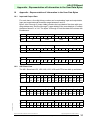
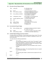
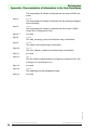
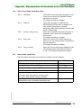
10 Appendix - Representation of Information in the User Data Bytes ... 31
10.1 Input and Output Data .......................................................................................... 31
10.2 AS-i Slave Lists ..................................................................................................... 31
10.3 Execution Control Flags (ec-flags) ...................................................................... 33
10.4 Host Interface Flags (hi-flags) .............................................................................33
10.5 Installed Software/Flags of the Host Interface ................................................... 33
10.6 AS-i Control Flags, Start/Stop Code ................................................................... 35
10.7 Non-volatile stored Data ....................................................................................... 35

AS-i PCI Board
Declaration of Conformity
Subject to reasonable modifications due to technical advances. Copyright Pepperl+Fuchs, Printed in Germany
Pepperl+Fuchs Group · Tel.: Germany (6 21) 7 76-0 · USA (3 30) 4 25 35 55 · Singapore 7 79 90 91 · Internet http://www.pepperl-fuchs.com
issue date 31.1.2001
5
1 Declaration of Conformity
The AS-i/PCI master VBM-CTR-PCI-DM has been developed and produced in accor-
dance with the applicable European standards and directives.
The manufacturer of the product, Pepperl+Fuchs Group in D-68301 Mannheim, pos-
sesses a certified quality assurance system in accordance with ISO 9001.
The corresponding of conformity can be requested from the manufacturer.
ISO9001

AS-Interface
Declaration of Conformity
Subject to reasonable modifications due to technical advances. Copyright Pepperl+Fuchs, Printed in Germany
Pepperl+Fuchs Group · Tel.: Germany (6 21) 7 76-0 · USA (3 30) 4 25 35 55 · Singapore 7 79 90 91 · Internet http://www.pepperl-fuchs.com
issue date 31.1.2001
6

AS-i PCI Board
The Used Symbols
Subject to reasonable modifications due to technical advances. Copyright Pepperl+Fuchs, Printed in Germany
Pepperl+Fuchs Group · Tel.: Germany (6 21) 7 76-0 · USA (3 30) 4 25 35 55 · Singapore 7 79 90 91 · Internet http://www.pepperl-fuchs.com
issue date 31.1.2001
7
2 The Used Symbols
This symbol warns the user of possible danger. Failure to heed this
warning can lead to personal injury or death and/or damage to equip-
ment.
This symbol warns the user of a possible failure. Failure to heed this
warning can lead to total failure of the equipment or any other con-
nected equipment.
This symbol gives the user important hints.

AS-Interface
The Used Symbols
Subject to reasonable modifications due to technical advances. Copyright Pepperl+Fuchs, Printed in Germany
Pepperl+Fuchs Group · Tel.: Germany (6 21) 7 76-0 · USA (3 30) 4 25 35 55 · Singapore 7 79 90 91 · Internet http://www.pepperl-fuchs.com
issue date 31.1.2001
8

AS-i PCI Board
Safety
Subject to reasonable modifications due to technical advances. Copyright Pepperl+Fuchs, Printed in Germany
Pepperl+Fuchs Group · Tel.: Germany (6 21) 7 76-0 · USA (3 30) 4 25 35 55 · Singapore 7 79 90 91 · Internet http://www.pepperl-fuchs.com
issue date 31.1.2001
9
3 Safety
3.1 Intended Use
3.2 General Safety Information
The protection of operating personnel and the system against possible
danger is not guaranteed if the control interface unit is not operated in
accordance with its intended use.
The device may only be operated by appropriately qualified personnel
in accordance with this operating manual.
Safety and correct functioning of the device cannot be guaranteed if any
operation other than that described in this operation manual is per-
formed.
The connecting of the equipment and any maintenance work to be car-
ried out with voltage applied to the equipment must only be performed
by appropriately qualified electrotechnical personnel.
In the case that a failure cannot be repaired, the device must be taken
out of operation and kept from inadvertently put back into operation.
Repair work is to be carried out by the manufacturer only. Additions or
modifications to the equipment are not allowed and void the warranty.
The operator is responsible for the observance of local safety stan-
dards.

AS-Interface
Safety
Subject to reasonable modifications due to technical advances. Copyright Pepperl+Fuchs, Printed in Germany
Pepperl+Fuchs Group · Tel.: Germany (6 21) 7 76-0 · USA (3 30) 4 25 35 55 · Singapore 7 79 90 91 · Internet http://www.pepperl-fuchs.com
issue date 31.1.2001
10

AS-i PCI Board
Features of the AS-i PCI Board
Subject to reasonable modifications due to technical advances. Copyright Pepperl+Fuchs, Printed in Germany
Pepperl+Fuchs Group · Tel.: Germany (6 21) 7 76-0 · USA (3 30) 4 25 35 55 · Singapore 7 79 90 91 · Internet http://www.pepperl-fuchs.com
issue date 31.1.2001
11
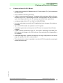
4 Features of the AS-i PCI Board
• contains two complete AS-i Masters with AS-i Control option (PLC), built as a board
for the PCI-bus.
• easy installation with "Plug and Play"
• is able to execute a control program. It operates without taking an affect to the per-
formance of your PC. The other way round the control program runs with a constant
cycle time independent from the PC capacity required by other applications.
• exchanges data with the PC via Dual Port RAM (DPRAM).
• An event mechanism can notify the PC application about changes of the data on
the board.
• Up to 4 AS-i PCI boards can operate in one PC system.
• is capable to generate an interrupt on the PCI-bus, for example if the AS-i data
changes.
• is able to detect a breakdown of the PC, if the built-in watchdog is activated (The
AS-i masters will change to the Off-line phase if the watchdog is not triggered by a
PC program).
• Advanced Diagnostics: to detect occasionally occuring configuration errors and to
judge the quality of the AS-i communication.
• The included driver makes it possible to use the AS-i PCI board with several appli-
cations simultaneously.

AS-Interface
Features of the AS-i PCI Board
Subject to reasonable modifications due to technical advances. Copyright Pepperl+Fuchs, Printed in Germany
Pepperl+Fuchs Group · Tel.: Germany (6 21) 7 76-0 · USA (3 30) 4 25 35 55 · Singapore 7 79 90 91 · Internet http://www.pepperl-fuchs.com
issue date 31.1.2001
12

AS-i PCI Board
Installation of the AS-i PCI Board
Subject to reasonable modifications due to technical advances. Copyright Pepperl+Fuchs, Printed in Germany
Pepperl+Fuchs Group · Tel.: Germany (6 21) 7 76-0 · USA (3 30) 4 25 35 55 · Singapore 7 79 90 91 · Internet http://www.pepperl-fuchs.com
issue date 31.1.2001
13
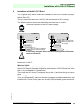
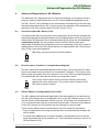
5 Installation of the AS-i PCI Board
The "Plug and Play"-feature makes the installation of the AS-i PCI Board very easy:
Switch off the PC.
Then just insert the board into a free PCI slot and connect the AS-i circuit(s).
The following pictures shows the possibilities to connect an AS-i circuit.
Now switch on the PC.
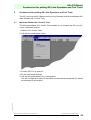
Windows 95/98:
If you have Windows 95 or Windows 98 you will be asked to insert the driver disk for
the AS-i PCI Board ("Windows 95/98 driver install disk for AS-i PCI Board"; this is the
disk 1 of the software AS-i Control Tools).
Then install the AS-i Control Tools (setup.exe on disk 1) and follow the given instruc-
tions.
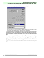
Windows NT:
If you have Windows NT, make sure that are you logged in as administrator, then just
install the AS-i Control Tools (setup.exe on disk 1) and follow the given instructions.
Connection samples for the AS-i power supply:
In the wiring schemes above the current through the AS-i master
must not exceed 5 A.
AS-i Master
max. 5 A
PELV according to EN
60950 (Protective extra
low voltage)
AS
-
i
power
supply
-
+
AS-i Slave
-
+
AS-i Slave
-
+
AS-i Master
max. 8 A
PELV according to EN 60950
(Protective extra low voltage)
AS
-
i
power
supply
-
+
AS-i Slave
-
+
AS-i Slave
-
+

AS-Interface
Installation of the AS-i PCI Board
Subject to reasonable modifications due to technical advances. Copyright Pepperl+Fuchs, Printed in Germany
Pepperl+Fuchs Group · Tel.: Germany (6 21) 7 76-0 · USA (3 30) 4 25 35 55 · Singapore 7 79 90 91 · Internet http://www.pepperl-fuchs.com
issue date 31.1.2001
14

AS-i PCI Board
Accessing the Data
Subject to reasonable modifications due to technical advances. Copyright Pepperl+Fuchs, Printed in Germany
Pepperl+Fuchs Group · Tel.: Germany (6 21) 7 76-0 · USA (3 30) 4 25 35 55 · Singapore 7 79 90 91 · Internet http://www.pepperl-fuchs.com
issue date 31.1.2001
15
6 Accessing the Data
6.1 Windows Device Drivers and DLLs
The AS-i PCI card comes with Windows device drivers for 95/98 and NT. In addition
to that there are the DLLs "asidrv32.dll" and "asipci.dll". These DLLs enable the user
to write its own Windows application. The use of these DLLs is described in the files
"readme.txt" and "aasidrv.h".
6.2 OPC-Server
Another possibility of data access is the use of the OPC-Server. The OPC-Server is
an easy possibility to use a wide variety of SCADA-systems together with the AS-i PCI
card.
6.3 Using the AS-i PCI card without the Windows Device Driver
The DPRAM of the AS-i PCI board is accessible both memory mapped and I/O
mapped. The PCI host system should provide ways (such as the PCI BIOS in case of
an IBM AT) to determine the I/O and/or memory base address and interrupt number.
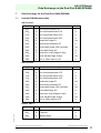
6.3.1 Register Map
6.3.2 DPRAM Access
The AS-i PCI board uses a 1 kByte, byte-wide DPRAM. The access to this DPRAM
is done through a 16 byte window starting at offset C0h.
To select the window for a certain DPRAM_address, set the register "AUX pin data"
at offset 03h according to the following formula:
"AUX pin data" = DPRAM_address/16 + 128
In other words, bits 20 to 25 of "AUX pin data" determine the bits 24 to 29 of the
DPRAM address. "AUX pin data", bit 27 should be set.
Offset Bits Description Value
00hsubsystem reset FFh: asserted, FEh: released
02h"AUX pin control" set to BFh
03h
0..5
6
7
"AUX pin data"
DPRAM window selection
interrupt request
interrupt acknowledge
initialize with 80h
04hset to 00h
05h"Interrupt mask" set to 40h to enable interrupts,
else set to 00h
07h"AUX pin status"
C0h...
FCh
DPRAM window

AS-Interface
Accessing the Data
Subject to reasonable modifications due to technical advances. Copyright Pepperl+Fuchs, Printed in Germany
Pepperl+Fuchs Group · Tel.: Germany (6 21) 7 76-0 · USA (3 30) 4 25 35 55 · Singapore 7 79 90 91 · Internet http://www.pepperl-fuchs.com
issue date 31.1.2001
16
To access a certain cell of the DPRAM within the DPRAM window, read or write at the
following offset:
offset = C0h + DPRAM_address mod 16 * 4
6.3.3 Interrupt Handling
Besides installing an interrupt handler on the PCI host and selecting an interrupt
source in the DPRAM, you have to set the "Interrupt mask" register at offset 05h to
40h in order to enable interrupt generation of the AS-i PCI board.
If the AS-i PCI asserts an interrupt, bit 26 of "AUX pin status" is set to zero. To ack-
nowledge the interrupt, set bit 27 of "AUX pin data" to zero and wait for bit 26 of "AUX
pin status" until it becomes ’1’. Afterwards, read the "Interrupt Event" DPRAM cell to
determine the interrupt source that caused the interrupt.
(If this is done within a interrupt handler, you should save and restore the contents of
the "AUX pin data" register in order to avoid switching the DPRAM window during
DPRAM access of an other task.)

AS-i PCI Board
Data Exchange via the Dual Port RAM (DPRAM)
Subject to reasonable modifications due to technical advances. Copyright Pepperl+Fuchs, Printed in Germany
Pepperl+Fuchs Group · Tel.: Germany (6 21) 7 76-0 · USA (3 30) 4 25 35 55 · Singapore 7 79 90 91 · Internet http://www.pepperl-fuchs.com
issue date 31.1.2001
17
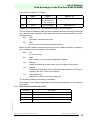
7 Data Exchange via the Dual Port RAM (DPRAM)
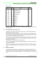
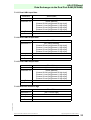
7.1 Detailed DPRAM Address Map
AS-i Circuit 1:
AS-i Circuit 2:
Device, Part 1:
address size data access
000h8 list of active slaves LAS r/–
008h8 list of detected slaves LDS r/–
010h8 list of projected slaves LPS r/–
018h8 list of peripheral faults LPF r/–
020h32 parameter image PI r/w
040h32 permanent parameter PP r/–
060h32 output data image ODI (inverted!) r/w
080h32 input data image IDI r/–
0A0h2 execution control flags ec-flags r/–
0A2h1 host interface flags hi-flags r/w
0A8h8 list of ‘offline slaves’ LOS r/–
address size data access
100h8 list of active slaves LAS r/–
108h8 list of detected slaves LDS r/–
110h8 list of projected slaves LPS r/–
118h8 list of peripheral faults LPF r/–
120h32 parameter image PI r/w
140h32 permanent parameter PP r/–
160h32 output data image ODI (inverted!) r/w
180h32 input data image IDI r/–
1A0h2 execution control flags ec-flags r/–
1A2h1 host interface flags hi-flags r/w
1A8h8 list of ‘offline slaves’ LOS r/–
address size data access
0C8h8 Date Code r/–
0D0h16 Features r/–
0E0h32 Master Name r/–

AS-Interface
Data Exchange via the Dual Port RAM (DPRAM)
Subject to reasonable modifications due to technical advances. Copyright Pepperl+Fuchs, Printed in Germany
Pepperl+Fuchs Group · Tel.: Germany (6 21) 7 76-0 · USA (3 30) 4 25 35 55 · Singapore 7 79 90 91 · Internet http://www.pepperl-fuchs.com
issue date 31.1.2001
18
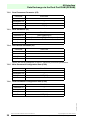
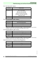
Device, Part 2:
If an AS-i Control program runs, buffers C and D are occupied by the AS-i Control user
memory (flags).
7.2 AS-i Master Execution Control Lists
All data of the AS-i master may be read at any time out of the DPRAM (addresses
000h to 0AFh resp. 100h to 1AFh).
The only lists, that are read cyclically by the AS-i master are the output data image
ODI, the host interface flags (hi-flags) and the parameter image PI. All other lists can
only be written by using the mailbox commands.
The AS-i master writes cyclically the input data image IDI, the execution control flags
(ec-flags), the list of active slaves LAS, the list of detected slaves LDS and the con-
figuration data image CDI.
Additionally, the installed software string is updated.
Due to the internal processing of the output data image ODI, the user has to store it
inverted to the DPRAM.
While a control program is running, it generates the new ODI, so the AS-i master
writes it to the DPRAM image. If an ODI was written by the PC, it will be overwritten
then.
7.3 Mailbox Commands
To read and write the execution control lists that are not directly accessibly in the
DPRAM the AS-i PC card has four mailboxes. These mailboxes have to be used as
well if commands like "Change Slaveaddress" or "Store Configuration" shall be exe-
cuted.
address size data access
1B9h1 Config_ok Delay r/w
1BAh1 Watchdog Enable r/w
1BBh1 Watchdog Counter r/w
1BCh2 Interrupt Enable r/w
1BEh2 Interrupt Event r/–
1C0h16 Mailbox A r/w
1D0h16 Mailbox B r/w
1E0h16 Mailbox C r/w
1F0h16 Mailbox D r/w
200h128 Buffer A r/w
280h128 Buffer B r/w
300h128 Buffer C r/w
380h128 Buffer D r/w

AS-i PCI Board
Data Exchange via the Dual Port RAM (DPRAM)
Subject to reasonable modifications due to technical advances. Copyright Pepperl+Fuchs, Printed in Germany
Pepperl+Fuchs Group · Tel.: Germany (6 21) 7 76-0 · USA (3 30) 4 25 35 55 · Singapore 7 79 90 91 · Internet http://www.pepperl-fuchs.com
issue date 31.1.2001
19
Each mailbox consists of 16 bytes:
In addition to that there is a 128 byte buffer assigned to each mailbox.
The command is initiated by writing a valid command value to the first byte of the mail-
box. After command execution, the master overwrites the command with one of the
following values:
00h:ACK
successful command execution
FFh:NAK
an error occured during command exectution
Before the AS-i Master overwrites the first byte of the mailbox with NAK, it writes an
error message to the second byte of the mailbox:
00h:OK
no error occured
01h:NOK
error occured, no more precise diagnosis available
10h: Request
invalid command value was written to the first byte of the mailbox
12h:CtrlBuff
command is not allowed in this mailbox because buffers C and D are oc-
cupied by the AS-i Control user memory.
13h: NotImplemented
command is valid but not implemented yet
The following mailbox commands are available:
(See chapter 10 for detailed explanation of the lists and parameters of the individual
commands).
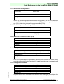
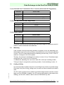
7.3.1 Write Permanent Parameter (PP)
byte 0 byte 1 byte 2...15
in command AS-i circuit
(0: AS-i circuit 1,
1: AS-i circuit 2)
parameter in
out result error message parameter out
command 3hex/3dec
parameter in –
parameter out –
buffer in PP[32]
buffer out –

AS-Interface
Data Exchange via the Dual Port RAM (DPRAM)
Subject to reasonable modifications due to technical advances. Copyright Pepperl+Fuchs, Printed in Germany
Pepperl+Fuchs Group · Tel.: Germany (6 21) 7 76-0 · USA (3 30) 4 25 35 55 · Singapore 7 79 90 91 · Internet http://www.pepperl-fuchs.com
issue date 31.1.2001
20
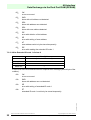
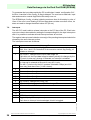
7.3.2 Read Permanent Parameter (PP)
7.3.3 Write Parameter (PI)
7.3.4 Store Actual Parameter (PI)
Stores the actual parameters of the AS-i slaves as permanent parameters.
7.3.5 Write Permanent Configuration Data (PCD)
7.3.6 Read Permanent Configuration Data (PCD)
command 4hex/4dec
parameter in –
parameter out –
buffer in –
buffer out PP[32]
command 5hex/5dec
parameter in [slave address][PI]
parameter out [slave address][PI][slave response]
buffer in –
buffer out –
command 7hex/7dec
parameter in –
parameter out –
buffer in –
buffer out –
command 8hex/8dec
parameter in –
parameter out –
buffer in PCD[128]
buffer out –
command 9hex/9dec
parameter in –
parameter out –
buffer in –
buffer out PCD[128]
Page is loading ...
Page is loading ...
Page is loading ...
Page is loading ...
Page is loading ...
Page is loading ...
Page is loading ...
Page is loading ...
Page is loading ...
Page is loading ...
Page is loading ...
Page is loading ...
Page is loading ...
Page is loading ...
Page is loading ...
Page is loading ...
Page is loading ...
Page is loading ...
-
 1
1
-
 2
2
-
 3
3
-
 4
4
-
 5
5
-
 6
6
-
 7
7
-
 8
8
-
 9
9
-
 10
10
-
 11
11
-
 12
12
-
 13
13
-
 14
14
-
 15
15
-
 16
16
-
 17
17
-
 18
18
-
 19
19
-
 20
20
-
 21
21
-
 22
22
-
 23
23
-
 24
24
-
 25
25
-
 26
26
-
 27
27
-
 28
28
-
 29
29
-
 30
30
-
 31
31
-
 32
32
-
 33
33
-
 34
34
-
 35
35
-
 36
36
-
 37
37
-
 38
38


Pepperl+Fuchs VBM-CTR-PCI-DM Owner's manual
- Type
- Owner's manual
Ask a question and I''ll find the answer in the document
Finding information in a document is now easier with AI
Related papers
-
Pepperl+Fuchs VBG-CCL-G4F Owner's manual
-
-
-
-
Pepperl+Fuchs VBG-PN-K20-DMD Owner's manual
-
-
-
-
-