
Please do not return product to retailer.
Por favor, no devuelva el producto al lugar de compra.
Veuillez ne pas retourner le produit au détaillant.
1--800--554--6723
www.poulanpro.com
Register your product online at:
Registre su producto en línea en:
Enregistrez votre produit en ligne à l’adresse :
ENGLISH ESPAÑOL FRANÇAIS
WARNING:
Read and follow all Safety Rules and Operating Instructions before
using this product. Failure to do so can result in serious injury.
ADVERTENCIA:
Lea el manual de instrucciones y siga todas las advertencias e
instrucciones de seguridad. El no hacerlo puede resultar en le-
siones graves.
AVERTISSEMENT:
Lire le manuel d’instructions et bien respecter tous les avertisse-
ments et toutes les instructions de sécurité. Tout défaut de le
faire pourrait entraîner des blessures graves.
Instruction Manual
Manual de Instrucciones
Manuel d’Instructions
PP28RJ
For Occasional Use Only
R
Husqvarna Consumer Outdoor Products
9335 Harris Corners Parkway
Charlotte, NC 28269
Husqvarna Consumer Outdoor Products
850 Matheson Blvd. West
Mississauga, Ontario L5V 0B4
115597026
Rev. 2 1/6/14 KAP LT28CSPR

2
TABLE OF CONTENTS
Identification of Safety Symbols 2
Safety Rules 3
Assembly 5
Operation 9
Maintenance 13
Service & Adjustments 14
Storage 17
Troubleshooting Table 18
Limited Warranty Statement 19
Emissions Statement 20
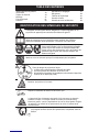
IDENTIFICATION OF SAFETY SYMBOLS
Maximum rotational frequency of the spindle, rpm.
Blade/trimmer line can throw objects violently. You can
be blinded or injured. Always wear safety glasses
marked Z87.
Always wear hearing protection, head protection,
heavy, long pants, long sleeves, boots and gloves.
Hazard zone for thrown objects.
SBlade/trimmer line throws objects violently.
SYou and others can be blinded/injured.
SKeep people and animals 50 feet (15 meters) away.
Secure hair above shoulder length.
Read the operator’s manual before use. Failure to follow instructions could
result in serious injury to the operator and/or bystanders. Save operator’s
manual.
Assist handle to be positioned only between the arrows.
This unit can be dangerous! Careless or improper use can cause serious
injury.
Watch out for thrown objects and ricochets.
Blade can thrust violently away from material it does not cut. Blade thrust
can cause amputation of arms or legs. Keep people and animals 50 feet
(15 meters) away.

3
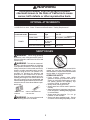
WARNING
The engine exhaust from this product contains
chemicals known to the State of California to cause
cancer, birth defects or other reproductive harm.
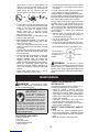
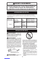
OPTIONAL ATTACHMENTS
Cutting attachment / guard,
Powerhead model Attachments Type part. no.
Trimmer head TNG 7 537419222 / 530096211
Grass blade/grass cutter 4-point blade, 530055892 / 574764801
8″(20 cm)
diameter
Brushcutter attachment PP4000C 952711610
These attachments used in combination with the specified powerhead have been evaluated
to ANSI B175.3--2013, “Grass Trimmers and Brushcutters -- Safety Requirements”:
PP28RJ
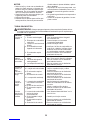
SAFETY RULES
WARNING:When using gardening
appliances, basic safety precautions must al-
ways be followed to reduce the risk of fire and
serious injury.
WARNING:This unit can cause seri-
ous injury including amputation or blindness
to the operator and others. The warnings and
safety instructions in this manual must be fol-
lowed to provide reasonable safety and effi-
ciency in using the unit. The operator is re-
sponsible for following the warnings and
instructions in this manual and on the unit.
Read the entire instruction manual before as-
sembling and using the unit! Restrict the use of
this unit to persons who read, understand, and
follow the warnings and instructions in this man-
ual and onthe unit. Never allow children to oper-
ate this unit.
SAFETY INFORMATION
ON THE UNIT
INSTRUCTION
MANUAL
WARNING:Do not use trimmer head
as a fastening device for the blade.
If situations occur which are not covered in this
manual, use care and good judgment. If you
need assistance, contact contact an authorized
service dealer or call customer support.
OPERATOR SAFETY
SDress properly. Always wear safety
glasses or similar eye protection when op-
erating, or performing maintenance on your
unit (safety glasses are available). Eye
protection should be marked Z87.
SAlways wear hearing protection.
SAlways wear face or dust mask if operation
is dusty.
SAlways wear heavy, long pants, long sleeves,
boots, and gloves. Wearing safety leg guards
is recommended.
SAlways wear foot protection. Do not go
barefoot or wear sandals.
SSecure hair above shoulder length. Secure
or remove loose clothing and jewelry or cloth-

4
ing with loosely hanging ties, straps, tassels,
etc. They can be caught in moving parts.
SBeing fully covered also helps protect you
from debris and pieces of toxic plants
thrown by spinning line/blade.
SStay alert. Do not operate unit when you are
tired, ill, upset or under influence of alcohol,
drugs, or medication. Watch what you are do-
ing; use common sense.
SNever start or run the engine inside a
closed room or building. Breathing exhaust
fumes can kill.
SKeep handles free of oil and fuel.
SAlways use the handlebar and a properly
adjusted shoulder strap with a blade (see
ASSEMBLY).
UNIT/MAINTENANCE SAFETY
WARNING:Stop unit and disconnect
the spark plug before performing mainte-
nance (except idle speed adjustments).
SLook for and replace damaged or loose
parts before each use. Look for and repair
fuel leaks before use. Keep unit in good
working condition.
SThrow away blades that are bent, warped,
cracked, broken, or damaged in any other
way. Replace trimmer head parts that are
cracked, chipped, broken, or damaged in
any other way before using the unit.
SMaintain unit according to recommended
procedures. Keep blade sharp. Keep cut-
ting line at the proper length.
SUse only specified replacement line. Never
use wire, rope, string, etc.
SInstall required shield properly before using
the unit.
SUse only specified blade or trimmer head;
make sure it is properly installed and se-
curely fastened.
SNever start engine with clutch shroud re-
moved. The clutch can fly off and cause se-
rious injury.
SBe sure blade or trimmer head stops turning
when engine idles.
SMake idle speed adjustments with the lower
end supported to prevent blade or trimmer line
from contacting any object. Hold unit by hand;
do not use the shoulder strap for support.
SKeep others away when making idle speed
adjustments.
SUse only recommended accessories and
replacement parts.
SHave all maintenance and service not ex-
plained in this manual performed by your au-
thorized service dealer.
FUEL SAFETY
SMix and pour fuel outdoors.
SKeep away from sparks or flames.
SUse a container approved for fuel.
SDo not smoke or allow smoking near fuel or
the unit or while using the unit.
SAvoid spilling fuel or oil. Wipe up all fuel
spills before starting engine.
SMove at least 10 feet (3 meters) away from
fueling site before starting engine.
SStop engine and allow it to cool before re-
moving fuel cap.
SEmpty the fuel tank before storing or trans-
porting the unit. Use up fuel left in the car-
buretor by starting the engine and letting it
run until it stops.
SStore unit and fuel in area where fuel vapors
cannot reach sparks or open flames from
water heaters, electric motors or switches,
furnaces, etc.
SAlways store gasoline in a container ap-
proved for flammable liquids.
CUTTING SAFETY
WARNING:Inspect area before
starting unit. Remove all debris and hard ob-
jects such as rocks, glass, wire, etc., that can
ricochet, be thrown, or otherwise cause injury
or damage during operation.
SKeep others including children, animals, by-
standers, and helpers at least 50 feet (15 me-
ters) away. Bystanders should be encour-
aged to wear safety glasses. Stop engine
immediately if you are approached.
SAlways keep engine on the right--hand side
of your body.
SHold the unit firmly with both hands.
SKeep firm footing and balance. Do not over-
reach.
SKeep blade or trimmer head below waist
level. Do not raise engine above your waist.
SKeep all parts of your body away from blade,
trimmer head, and muffler when engine is run-
ning. A hot muffler can cause serious burns.
SCut from your left to your right. Cutting on
right side of the shield will throw debris
away from the operator.
SUse only in daylight or good artificial light.
SUse only for jobs explained in this manual.
TRANSPORTING AND STORAGE
SStop the unit before carrying.
SKeep muffler away from your body.
SAllow the engine to cool and secure the unit
before storing or transporting it in a vehicle.
SEmpty the fuel tank before storing or trans-
porting the unit. Use up fuel left in the carbu-
retor by starting the engine and letting it run
until it stops.
SStore unit and fuel in area where fuel vapors
cannot reach sparks or open flames from
water heaters, electric motors or switches,
furnaces, etc.
SStore unit so the blade or line limiter blade
cannot accidentally cause injury. The unit
can be hung by the shaft.
SStore unit out of reach of children.
SAFETY NOTICE: Exposure to vibrations
through prolonged use of gasoline powered
hand tools could cause blood vessel or nerve
damage in the fingers, hands, and joints of
people prone to circulation disorders or ab-
normal swellings. Prolonged use in cold
weather has been linked to blood vessel dam-
age in otherwise healthy people. If symptoms
occur such as numbness, pain, loss of
strength, change in skin color or texture, or
loss of feeling in the fingers, hands, or joints,
discontinue the use of this tool and seek med-
ical attention. An anti--vibration system does
not guarantee the avoidance of these prob-

5
lems. Users who operate power tools on a
continual and regular basis must monitor
closely their physical condition and the condi-
tion of this tool.
SPECIAL NOTICE: This unit is equipped
with a temperature limiting muffler and spark
arresting screen which meets the require-
ments of California Codes 4442 and 4443. All
U.S. forest land and the states of California,
Idaho, Maine, Minnesota, New Jersey, Ore-
gon, and Washington require by law that
many internal combustion engines be
equipped with a spark arresting screen. If you
operate in a locale where such regulations ex-
ist, you are legally responsible for maintaining
the operating condition of these parts. Failure
to do so is a violation of the law. For normal
homeowner use, the muffler and spark arrest-
ing screen will not require any service. After
50 hours of use, we recommend that your
muffler be serviced or replaced by your autho-
rized service dealer.
ADDITIONAL SAFETY RULES
FOR OPTIONAL ATTACHMENTS
WARNING:For each optional attach-
ment used, read entire instruction manual be-
fore use and follow all warnings and instruc-
tions in manual and on attachment.
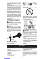
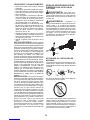
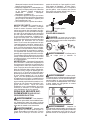
WARNING:Ensure handlebar is
installed when using brushcutter attachment.
Attach handlebar between arrows on safety la-
bel on the upper shaft (engine end of unit). If
your brushcutter attachment does not include a
handlebar, a handlebar accessory kit
(#530071451) is available from your authorized
service dealer.
Handlebar
BRUSHCUTTER SAFETY
Blade can thrust violently away from material
it does not cut. Blade thrust can cause am-
putation of arms or legs.
Do not use trimmer head as a fastening de-
vice for the blade.
The blade continues to spin after the trigger is
released or engine is turned off. The coasting
blade can throw objects or seriously cut you if
accidentally touched. Stop the blade by con-
tacting the right hand side of the coasting
blade with material already cut.
WARNING:Inspect area before
starting unit. Remove all debris and hard ob-
jects such as rocks, glass, wire, etc., that can
ricochet, be thrown, or otherwise cause injury
or damage during operation.
SThrow away and replace blades that are
bent, warped, cracked, broken or damaged
in any other way.
SInstall required shield properly before using
the unit.
SUse only specified blade and make sure it is
properly installed and securely fastened.
SCut from your left to your right. Cutting on
the right side of the shield will throw debris
away from the operator.
SAlways use the handlebar and a properly
adjusted shoulder strap with blade (see AS-
SEMBLY).
ASSEMBLY
CARTON CONTENTS
Check carton contents against the following list:
SPowerhead
SAttachment (with trimmer head installed)
SCupped washer
SLarge nut for installing blades
SHex wrench
SHandlebar
SBracket cover
SBracket cover screws (2)
S4--point weed blade
SPlastic shield
SWing nut (screwed onto plastic shield)
SShoulder strap with warning
SContainer of oil
CAUTION: Always stop unit and discon-
nect spark plug before performing any as-
sembly procedures. If received assembled,
repeat all steps to ensure your unit is properly
assembled and all fasteners are secure.
Examine parts for damage. Do not use dam-
aged parts.

6
NOTE: If you need assistance or find parts
missing or damaged, call customer support.
It is normal for the fuel filter to rattle in the
empty fuel tank.
Finding fuel or oil residue on muffler is normal
due to carburetor adjustments and testing
done by the manufacturer.
TOOLS REQUIRED
SHex wrench (provided)
SAdjustable wrench
SPhillips screwdriver
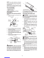
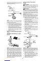
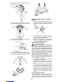
INSTALLING BRUSHCUTTER
ATTACHMENT
CAUTION: When installing brushcutter at-
tachment, place the unit on a flat surface for
stability.
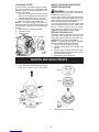
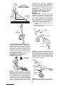
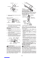
1. Loosen the coupler by turning the knob
counterclockwise.
Shipping
protector
Coupler
Knob
LOOSEN
TIGHTEN
2. Remove shipping protector from coupler.
3. Remove the shaft cap from the brushcutter
attachment (if present).
4. Position locking/release button of attach-
ment into guide recess of coupler.
5. Push the attachment into the coupler until
the locking/release button snaps into the
primary hole.
6. Before using the unit, tighten the knob se-
curely by turning clockwise.
Coupler Primary Hole
Upper
Shaft
Locking/
Release
Button
Attachment
Guide Recess
WARNING:Make sure the locking/
release button is locked in the primary hole
and the knob is securely tightened before op-
erating the unit. All attachments are designed
to be used in the primary hole unless other-
wise stated in the applicable attachment in-
struction manual. Using the wrong hole could
lead to serious injury or damage to the unit.
Locking/Release
Button in Primary Hole
For assembly of optional attachments, refer
to the ASSEMBLY section of the applicable
attachment instruction manual.
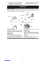
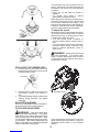
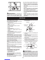
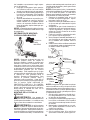
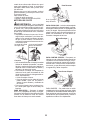
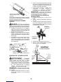
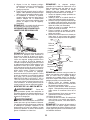
ATTACHING THE HANDLEBAR
DANGER:To avoid serious injury, the
barrier portion of the handlebar must be installed
as shown to provide a barrier between operator
and the spinning blade.
1. Locate the decal on the handlebar. This
decal includes arrows showing the direc-
tion toward the engine and the bracket
locator pin.
2. Position the bracket cover over the
handlebar. Make sure the hole in the
handlebar is positioned on the bracket
locator pin.
3. Insert screws and hand tighten only. Be
sure the handlebar is installed correctly;
then, tighten each screw securely with
the hex wrench.
Screw
Mounting
Bracket
Handlebar
Bracket
Cover
Shoulder
Strap Clamp
Bracket
Locator Pin
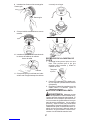
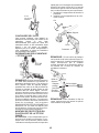
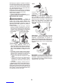
ASSEMBLY OF SHOULDER STRAP
WARNING:Proper shoulder strap
and handlebar adjustments must be made
with the engine completely stopped before
using unit.
1. Insert your right arm and head through
the shoulder strap and allow it to rest on
your left shoulder. Make sure the danger
sign is on your back and the hook is to the
right side of your waist.
NOTE: A one-half twist is built in the shoul-
der strap to allow the strap to rest flat on the
shoulder.
2. Adjust the strap, allowing the hook to be
about 6 inches (15 cm) below the waist.
3. Fasten the strap hook to the clamp located
between the throttle trigger and the handle-
bar mounting bracket and lift the tool to the
operating position.

7
4. Try on shoulder strap and adjust for fit
and balance before starting the engine or
beginning a cutting operation.
NOTE: It may be necessary to relocate the
shoulder strap clamp on the shaft for proper
balancing of unit.
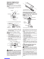
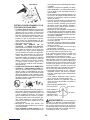
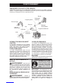
TO RELOCATE SHOULDER STRAP
CLAMP:
1. Loosen and remove both clamp screws.
2. Place the upper shoulder strap clamp
over the shaft.
3. Position the lower shoulder strap clamp
under the shaft and align the upper and
lower clamp screw holes.
Upper Shoulder
Strap Clamp
Screws
Lower Shoulder
Strap Clamp
4. Insert two screws into the screw holes.
5. Secure shoulder strap clamp by tighten-
ing screws with a hex wrench.
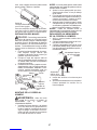
SHOULDER STRAP
ADJUSTMENT
FOR BALANCE
6 inches
(15 cm)
below
waist
30 inches
(76 cm)
minimum
4 -- 12 inches
(10 -- 30 cm)
above
ground
30 inches
(76 cm)
minimum
CONFIGURING YOUR UNIT
You can configure your unit using a cutting head
for grass and light weeds, or a weed blade for
cutting grass, weeds, and brush up to 1/2 inch
(1 cm) in diameter. To assemble your unit, go to
the section for the desired configuration and fol-
low the instructions.
ASSEMBLY INFORMATION --
TRIMMER HEAD
TRIMMER
HEAD
NOTE: Remove the blade before attaching the
trimmer head. To remove blade, align hole in
the dust cup with the hole in the side of the
gearbox by rotating the blade. Insert a small
screwdriver into aligned holes. This will keep
the shaft from turning while loosening the blade
nut. Remove blade nut by turning clockwise.
Remove the screwdriver. Remove both wash-
ers and blade. See INSTALLATION OF THE
METAL BLADE for illustrations. Be sure to store
all parts and instructions for future use.
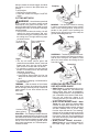
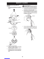
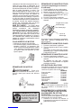
ATTACHING THE PLASTIC SHIELD
AND TRIMMER HEAD
CAUTION: The shield must be properly
installed. The shield provides partial protec-
tion to the operator and others from the risk of
thrown objects, and is equipped with a line
limiter blade which cuts excess line to the
proper length. The line limiter blade (on un-
derside of shield) is sharp and can cut you.
1. Insert bracket into slot on shield.
2. Install hex screw using included wrench
and tighten securely.
Bracket
Slot
Shield
Screw
Wrench
NOTE: If your unit has a plastic cover over
the threads on the threaded shaft, remove the
covering to expose the threads. Beforeinstal-

8
ling the trimmer head, make sure the dust cup
and retaining washer are positioned on the
gearbox as shown below.
Retaining
Washer
Dust Cup
Gearbox
Aligned Holes
NOTE: Make sure all parts are properly
installed as shown in the illustration before
installing the trimmer head.
5. Align hole in the dust cup with the hole in the
side of the gearbox by rotating the dust cup.
6. Insert a small screwdriver into aligned
holes. This will keep the shaft from turn-
ing while tightening trimmer head.
7. While holding the screwdriver in position,
thread trimmer head onto the shaft in the
direction shown on the decal (counter-
clockwise looking from bottom of unit).
Tighten until secure.
NOTE: The retaining washer must be posi-
tioned with the raised section facing toward the
gearbox.
ASSEMBLY INFORMATION -- WEED
BLADE
WEED
BLADE
NOTE: Remove the trimmer head before at-
taching the weed blade. To remove the trimmer
head, align hole in the dust cup with the hole in
the side of the gearbox by rotating the dust cup.
Insert a small screwdriver into aligned holes.
This will keep the shaft from turning while loos-
ening the trimmer head. Remove the trimmer
head by turning clockwise. Remove the screw-
driver. See ATTACHING THE PLASTIC
SHIELD AND TRIMMER HEAD for illustra-
tions. Be sure to store all parts and instructions
for future use. Never use the trimmer head with
the metal blade installed.
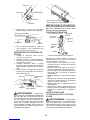
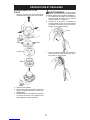
INSTALLATION OF THE METAL
BLADE
WARNING:Wear protective gloves
when handling or performing maintenance on
the blade to avoid injury. The blade is sharp and
can cut you even when it is not moving.
WARNING:Do not use any blades, or
fastening hardware other than the washers and
nuts shown in the following illustrations. These
parts must be provided by the manufacturer
and installed as shown below. Failure to use
proper parts can cause the blade to fly off and
seriously hurt you or others.
NOTE: The dust cup and retaining washer are
located on the gearbox shaft and not in the parts
bag. All other fasteners mentioned in the follow-
ing assembly steps are in the parts bag.
1. Remove the retaining washer from the
threaded shaft of the gearbox. Leave the
dust cup on the shaft.
2. Install the blade and the retaining washer
over the threaded shaft.
3. Make sure the raised part of the retaining
washer is facing the gearbox and the
raised area fits into the hole in the center
of the blade.
4. Slide the blade and retaining washer onto
the shaft of the gearbox.
5. Place the cupped washer onto the shaft.
Make sure the cupped side of the washer
is toward the blade.
6. Install the blade nut by threading onto the
shaft counterclockwise (looking from bot-
tom of unit).
Blade
Retaining
Washer
Cupped
Washer
Nut
Dust Cup
Gearbox
Aligned Holes
NOTE: Make sure all parts are in place as il-
lustrated, and the blade is sandwiched between
the dust cup and the retaining washer. There
should be no space between the blade and the
dust cup or the retaining washer.
7. Align hole in dust cup with hole in side of
gearbox by rotating the blade.
8. Insert a small screwdriver into aligned
holes. This will keep the shaft from turn-
ing while tightening the blade nut.
9. TIghten blade nut firmly with a wrench while
holding screwdriver in position.
10. Remove the screwdriver.

9
11. Turn blade by hand. If the blade binds
against the shield, or appears to be uneven,
the blade is not centered, and you must re-
install. NOTE: To remove blade, insert
screwdriver into aligned holes. Unthread
the nut and remove parts. Be sure to store
parts and instructions for future use.
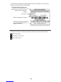
OPERATION
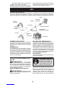
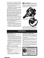
KNOW YOUR UNIT
READ THIS INSTRUCTION MANUAL AND SAFETY RULES BEFORE OPERATING YOUR UNIT.
Compare the illustrations with your unit to familiarize yourself with the location of the various controls
and adjustments. Save this manual for future reference.
Line Limiter
Blade
Handlebar
ON/STOP
Switch
Shield
Trimmer Head
Shaft
Coupler
Blade
Muffler
Start
Lever
Starter Handle
Primer Bulb
Throttle Trigger
Spark Plug
ON/STOP SWITCH
The ON/STOP switch is located on the trigger
handle and is used to stop the engine. To stop
the engine, push and release the engine
ON/STOP switch.
PRIMER BULB
The PRIMER BULB removes air from the car-
buretor and fuel lines and fills them with fuel.
This allows you to start the engine with fewer
pulls on the starter rope. Activate the primer
bulb by pressing it and allowing it to return to
its original form.
START LEVER
The START LEVER helps to supply fuel to the
engine to aid in starting. Activate the starting
system by moving the start lever to the START
position.
COUPLER
The COUPLER enables optional attach-
ments to be installed on the unit.

10
BEFORE STARTING ENGINE
WARNING:Be sure to read the fuel
information in the safety rules before you be-
gin. If you do not understand the safety rules,
do not attempt to fuel your unit. Call customer
support.
FUELING ENGINE
WARNING:Remove fuel cap slowly
when refueling.
HELPFUL TIP
To obtain the correct oil mix
ratio, pour 2.6 ounces of
2--cycle synthetic oil into
one gallon of fresh gas.
IMPORTANT: This equipment is designed to
operate on unleaded gasoline with a minimum
87 octane (R+M/2 method), with ethanol blen-
ded up to 10% maximum by volume (E-10). Be-
fore operation, gasoline must be mixed with a
good quality synthetic 2-cycle air-cooled engine
oil designed to be mixed at a ratio of 50:1. Mix
gasoline and oil at a ratio of 50:1. A 50:1 ratio is
obtained by mixing 2.6 fluid ounces of oil with 1
gallon of unleaded gasoline. DO NOT USE
automotive oil or marine oil. These oils will
cause engine damage. When mixing fuel, follow
instructions printed on container. Once oil is ad-
ded to gasoline, shake container momentarily to
assure that the fuel is thoroughly mixed. Always
read and follow the safety rules relating to fuel
before fueling your unit. Purchase fuel in quantit-
ies that can be used within 30 days to assure
fuel freshness.
CAUTION: Never use straight gasoline in
your unit. This will cause permanent engine
damage and void the limited warranty.Do not
use alternate fuels such as ethanol blends
above 10% by volume (E-15, E-85) or any
methanol blended fuel. Use of these fuels can
cause major engine performance and durability
problems.
HOW TO STOP YOUR UNIT
SRelease the throttle trigger.
SPush and release the engine ON/STOP
switch. The switch will automatically return to
the ON position. Wait 5 seconds before at-
tempting to restart unit to allow switch to reset.
ON/STOP
switch
HOW TO START YOUR UNIT
WARNING:Avoid any contact with the
muffler. A hot muffler can cause serious burns.
Starting Position
HELPFUL TIP
If your engine still does not
start after following these
instructions, please call
customer support.
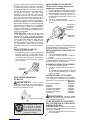
STARTING A COLD ENGINE (or a
warm engine after running out of
fuel)
1. Set unit on a flat surface.
2. Slowly press the primer bulb 6 times.
3. Move start lever to the START position.
4. Pull starter rope handle sharply 5 times. If
the temperature is above 90°F (32°C),
pull 3 times.
5. Squeeze and hold trigger.
6. Pull starter rope handle until engine
starts.
Primer bulb
Starter handle
Start lever
If the engine does not start, it is probably
flooded. Proceed to STARTING A FLOODED
ENGINE.
STARTING A WARM ENGINE
1. Squeeze and hold trigger.
2. Pull starter rope handle until engine starts.
If the engine does not start, it is probably
flooded. Proceed to STARTING A FLOODED
ENGINE.
STARTING A FLOODED ENGINE
1. Squeeze and hold trigger.
2. Pull starter rope handle until engine starts.
If the unit still does not start, refer to
TROUBLESHOOTING TABLE or call cus-
tomer support.
OPERATING THE COUPLER
This model is equipped with a coupler which
enables optional attachments to be installed.
The optional attachments are:
MODEL:
Edger PP1000E....................
Cultivator PP2000T. . . . . . . . . . . . . . . . .
Blower PP3000B...................
Brushcutter PP4000C. . . . . . . . . . . . . . .
Pruner PP5000P...................
Pruner PP5500P...................
Hedge Trimmer PP6000H. . . . . . . . . . . .
WARNING:Always stop unit and dis-
connect spark plug before removing or instal-
ling attachments.

11
REMOVING TRIMMER ATTACH-
MENT (OR OTHER OPTIONAL
ATTACHMENTS)
CAUTION: When removing or installing at-
tachments, place the unit on a flat surface for
stability.
1. Loosen the coupler by turning the knob
counterclockwise.
Attachment
Coupler
Knob
LOOSEN
TIGHTEN
2. Press and hold the locking/release button.
Locking/Release
Button
Coupler Upper Shaft
Attachment
3. While securely holding the engine and
upper shaft, pull the attachment straight
out of the coupler.
INSTALLING OPTIONAL ATTACH-
MENTS
1. Remove the shaft cap from the attach-
ment (if present).
2. Position locking/release button of attach-
ment into guide recess of coupler.
3. Push the attachment into the coupler until
the locking/release button snaps into the
primary hole.
4. Before using the unit, tighten the knob se-
curely by turning clockwise.
Coupler Primary Hole
Upper
Shaft
Locking/
Release
Button
Attachment
Guide Recess
WARNING:Make sure the locking/
release button is locked in the primary hole
and the knob is securely tightened before op-
erating the unit. All attachments are designed
to be used in the primary hole unless otherwise
stated in the applicable attachment instruction
manual. Using the wrong hole could lead to seri-
ous injury or damage to the unit.
Locking/Release
Button in Primary Hole
OPERATING INSTRUCTIONS
It is recommended that the engine not be
operated for longer than 1 minute at full
throttle.
OPERATING POSITION
ALWAYS WEAR:
Hearing
protection Eye protection
Heavy,
long pants
Boots
Cut from your left to your right.
Safety helmet
When operating unit, clip shoulder strap onto
clamp, stand as shown and check for the fol-
lowing:
SWear hearing protection, eye protection,
head protection and heavy clothing.
SExtend your left arm and hold handlebar
grip with your left hand.
SHold throttle grip with your right hand with
finger on throttle trigger.
SKeep unit below waist level.
SKeep shoulder strap pad centered on your
left shoulder and danger sign centered on
your back.
SMaintain full weight of tool on your left
shoulder.
SWithout bending over, keep the blade or
trimmer head near and parallel to the
ground and not crowded into material being
cut.
OPERATING INSTRUCTIONS FOR
USE WITH TRIMMER HEAD
WARNING:Always wear eye protec-
tion. Never lean over the trimmer head. Rocks
or debris can ricochet or be thrown into eyes
and face and cause blindness or other serious
injury.
Before trimming, bring engine to a speed suffi-
cient to cut material to be trimmed.
Do not run the engine at a higher speed than
necessary. The cutting line will cut efficiently
when the engine is run at less than full throttle.
At lower speeds, there is less engine noise and
vibration.

12
Always release the throttle trigger and allow
the engine to return to idle speed when not
cutting.
To stop engine:
SRelease the throttle trigger.
SPush and release the engine ON/STOP
switch.
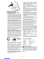
CUTTING METHODS
WARNING:Use minimum speed and
do not crowd the line when cutting around
hard objects (rock, gravel, fence posts, etc.),
which can damage the trimmer head, become
entangled in the line, or be thrown causing a
serious hazard.
SThe tip of the line does the cutting. You will
achieve the best performance and mini-
mum line wear by not crowding the line into
the cutting area. The right and wrong ways
are shown below.
Tip of the line
does the cutting.
Right Wrong
Line crowded into
work area.
SThe line will easily remove grass and
weeds from around walls, fences, trees and
flower beds, but it also can cut the tender
bark of trees or shrubs and scar fences.
SFor trimming or scalping, use less than full
throttle to increase line life and decrease
head wear, especially:
SDuring light duty cutting.
SNear objects around which the line can
wrap such as small posts, trees or fence
wire.
SFor mowing or sweeping, use full throttle for
a good clean job.
TRIMMING -- Hold the bottom of the trimmer
head about 3 inches (8 cm) above the ground
and at an angle. Allow only the tip of the line to
make contact. Do not force trimmer line into
work area.
Trimming
3 inches (8 cm)
above ground
SCALPING -- The scalping technique removes
unwanted vegetation down to the ground. Hold
the bottom of the trimmer head about 3 inches
(8 cm) above the ground and at an angle. Allow
the tip of the line to strike the ground around
trees, posts, monuments, etc. This techniquein-
creases line wear.
Scalping
MOWING -- Your trimmer is ideal for mowing
in places conventional lawn mowers cannot
reach. In the mowing position, keep the line
parallel to the ground. Avoid pressing the
head into the ground as this can scalp the
ground and damage the tool.
Mowing
SWEEPING -- The fanning action of the rotat-
ing line can be used to blow away loose debris
from an area. Keep the line parallel to and
above the area surface and swing the tool
from side to side.
Sweeping
OPERATING INSTRUCTIONS FOR
USE WITH WEED BLADE
SBlade Thrust is a reaction that only occurs
when using a bladed unit. This reaction can
cause serious injury such as amputation.
Carefully study this section. It is important that
you understand what causes blade thrust,
how you can reduce the chance of its
occurring, and how you can remain in control
of unit if blade thrust occurs.
SWHAT CAUSES BLADE THRUST -- Blade
Thrust can occur when the spinning blade
contacts an object that it does not cut. This
contact causes the blade to stop for an instant
and then suddenly move or “thrust” away
from the object that was hit. The “thrusting”
reaction can be violent enough to cause the
operator to be propelled in any direction and
lose control of the unit. The uncontrolled unit
can cause serious injury if the blade contacts
the operator or others.
SWHEN BLADE THRUST OCCURS --
Blade Thrust can occur without warning if
the blade snags, stalls, or binds. This is

13
more likely to occur in areas where it is
difficult to see the material being cut. By
using the unit properly, the occurrence of
blade thrust will be reduced and the
operator will be less likely to lose control.
SCut only grass, weeds, and woody brush up
to 1/2 inch (1 cm) in diameter with the weed
blade. Do not let the blade contact material
it cannot cut such as stumps, rocks,
fences, metal, etc., or clusters of hard,
woody brush having a diameter greater
than 1/2 inch (1 cm).
SKeep the blade sharp. A dull blade is more
likely to snag and thrust.
SCut only at full throttle. The blade will
have maximum cutting power and is less
likely to bind or stall.
S“Feed” the blade deliberately and not too
rapidly. The blade can thrust away if it is fed
too rapidly.
SCut only from your left to your right. Cutting on
right side of the shield will throw debris away
from the operator.
SUse the shoulder strap and keep a firm grip
on the unit with both hands. A properly
adjusted shoulder strap will support the
weight of the unit, freeing your arms and
hands to control and guide the cutting motion.
SKeep feet comfortably spread apart and
braced for a possible sudden, rapid thrust of
unit. Do not overreach. Keep firm footing and
balance.
SKeep blade below waist level; it will be
easier to maintain control of unit.
SDo not raise theengine above your waist as
the blade can come dangerously close to
your body.
SDo not swing unit with such force that you
are in danger of losing your balance.
Bring the engine to cutting speed before enter-
ing the material to be cut.If the blade does not
turn when you squeeze the throttle trigger, make
sure shaft is fully inserted into the engine.
Always release the throttle trigger and allow
engine to return to idle speed when not cut-
ting. The blade should not turn while the en-
gine is running at idle. If the blade turns at idle,
do not use your unit. Refer to IDLE SPEED
ADJUSTMENT or contact your authorized
service dealer.
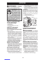
SMaintain good firm footing while using the
unit. Do this by planting feet firmly in a
comfortable apart position.
SCut while swinging the upper part of your
body from left to right.
SAs you move forward to the next area to cut,
be sure to maintain your balance and footing.
Cut using the 2
o’clock to 4 o’clock
position of the
blade
2 o’clock
4 o’clock
RECOMMENDED CUTTING POSITION
WARNING:The operator or others
must not try to clear away cut material with the
engine running or the blade turning to avoid
serious injury. Stop engine and blade before
removing materials wrapped around blade or
shaft.
MAINTENANCE
WARNING:Disconnect the spark
plug before performing maintenance except
for idle speed adjustments.
HELPFUL TIP
IMPORTANT: Have all
repairs other than the rec-
ommended maintenance
described in the instruction
manual performed by an
authorized service dealer.
If any dealer other than an authorized
service dealer performs work on the
product, the manufacturer may not pay
for repairs under warranty. It is your re-
sponsibility to maintain and perform
general maintenance.
CHECK FOR LOOSE
FASTENERS AND PARTS
SSpark Plug Boot
SAir Filter
SHousing Screws
SAssist Handle Screw
SDebris Shield
CHECK FOR DAMAGED OR
WORN PARTS
Contact an authorized service dealer for re-
placement of damaged or worn parts.
SON/STOP Switch -- Ensure ON/STOP
switch functions properly by pushing and
releasing the switch. Make sure engine
stops. Wait 5 seconds before attempting to
restart unit to allow switch to reset. Restart
engine and continue.
SFuel Tank -- Discontinue use of unit if fuel
tank shows signs of damage or leaks.
SDebris Shield -- Discontinue use of unit if
debris shield is damaged.
INSPECT AND CLEAN UNIT AND DE-
CALS
SAfter each use, inspect complete unit for
loose or damaged parts. Clean the unit and
decals using a damp cloth with a mild deter-
gent.
SWipe off unit with a clean dry cloth.

14
CLEAN AIR FILTER
A dirty air filter decreases engine perform-
ance and increases fuel consumption and
harmful emissions. Always clean after every
5 hours of operation.
1. Clean the cover and the area around it to
keep dirt from falling into the carburetor
chamber when the cover is removed.
2. Press the tabs on the air filter cover to re-
move the air filter cover and air filter.
NOTE: To avoid creating a fire hazard or
producing harmful evaporative emissions, do
not clean filter in gasoline or other flammable
solvent.
3. Wash the filter in soap and water.
4. Allow filter to dry.
5. Replace parts.
Tabs Air filter
Air filter
cover
INSPECT MUFFLER AND SPARK
ARRESTING SCREEN
WARNING:The muffler on this prod-
uct contains chemicals known to the State of
California to cause cancer.
As your unit is used, carbon deposits build up
on the muffler and spark arresting screen and
must be removed to avoid creating a fire haz-
ard or affecting engine performance.
For normal homeowner use, the muffler and
spark arresting screen will not require any
service. After 50 hours of use, we recom-
mend that your muffler be serviced or re-
placed by an authorized service dealer.
REPLACE SPARK PLUG
Replace the spark plug each year to ensure
the engine starts easier and runs better. Set
spark plug gap at 0.025 inch (0.6 mm). Igni-
tion timing is fixed and nonadjustable.
NOTE: This spark ignition system complies
with the Canadian standard ICES--002.
1. Twist, then pull off spark plug boot.
2. Remove spark plug from cylinder and
discard.
3. Replace with Champion RCJ-6Y spark
plug and tighten securely with a 3/4 inch
(19 mm) socket wrench.
4. Reinstall the spark plug boot.
SERVICE AND ADJUSTMENTS
REPLACING THE LINE
1. Press the tabs on the side of the trimmer
head and remove cover and spool.
Tab
Tab
Cover
Spool
2. Remove any remaining line.

15
3. Clean dirt and debris from all parts. Re-
place spool if it is worn or damaged.
4. Replace with a pre-wound spool, or re-
place line using a 25 feet (8 meters)
length of 0.095 inch (2.4 mm) diameter
line.
WARNING:Never use wire, rope,
string, etc., which can break off and become a
dangerous projectile.
5. When installing new line on an existing
spool, hold the spool as shown.
6. Bend the line at the midpoint and insert
the bend into the slot in the center rim of
the spool. Ensure line snaps into position
in the slot.
Slot
7. With your finger between the lines, wrap
the lines evenly and firmly around the
spool in a clockwise direction.
8. Position the lines in the guide slots.
Guide slot
Guide slot
9. Place the spool in the cover as shown
below.
10. Insert the ends of the lines through exit
holes in the sides of the cover.
Line exit hole
Cover
11. Reinstall the spool and cover onto the
trimmer head. Push until cover snaps into
place.

16
REPLACING THE TRIMMER HEAD
1. Hold the dust cup with a wrench to keep
the shaft from turning while removing and
installing trimmer head.
Dust Cup
2. Remove trimmer head by turning coun-
terclockwise (looking from bottom of
unit).
3. Thread replacement trimmer head onto the
shaft by turning clockwise. Only tighten
hand tight!
BLADE REPLACEMENT
Refer to the ASSEMBLY section for blade re-
placement instructions and illustrations.
IDLE SPEED ADJUSTMENT
WARNING:Keep others away when
making idle speed adjustments. The trimmer
head, blade or any optional attachment will be
spinning during most of this procedure. Wear
your protective equipment and observe all safe-
ty precautions. After making adjustments, the
trimmer head, blade or any optional attachment
must not move/spin at idle speed.
The carburetor has been carefully set at the
factory. Adjustment of the idle speed may be
necessary if you notice any of the following
conditions:
SEngine will not idle when the throttle is
released.
SThe trimmer head, blade or optional
attachment moves/spins at idle.
Make adjustments with the unit supported so
the cutting attachment is off the ground and
will not make contact with any object. Hold
the unit by hand while running and making ad-
justments. Keep all parts of your body away
from the cutting attachment and muffler.
To adjust idle speed:
Allow engine to idle. Adjust speed until engine
runs without trimmer head, blade or optional
attachment moving or spinning (idle too fast)
or stalling (idle speed too slow).
STurn idle speed screw clockwise to
increase engine speed if engine stalls or
dies.
STurn idle speed screw counterclockwise to
decrease engine speed if trimmer head,
blade or optional attachment moves or
spins at idle.
WARNING:Recheck the idle speed
after each adjustment. The trimmer head,
blade or optional attachment must not move
or spin at idle speed to avoid serious injury to
the operator or others.
Idle speed screw
If you require further assistance or are unsure
about performing this procedure, contact an
authorized service dealer or call customer
support.

17
STORAGE
CAUTION: Perform the following steps af-
ter each use:
SAllow engine to cool before storing or trans-
porting.
SStore unit and fuel in a well ventilated area
where fuel vapors cannot reach sparks or
open flames from water heaters, electric
motors or switches, furnaces, etc.
SStore unit with all guards in place. Position
unit so that any sharp object cannot acci-
dentally cause injury.
SStore unit and fuel well out of the reach of
children.
SEASONAL STORAGE
Prepare unit for storage at end of season or if
it will not be used for 30 days or more.
If your unit is to be stored for a period of time:
SClean the entire unit before lengthy
storage.
SStore in a clean dry area.
SLightly oil external metal surfaces.
FUEL SYSTEM
Under FUELING ENGINE in the OPERA-
TION section of this manual, see message la-
beled IMPORTANT regarding the use of
proper fuel in your engine.
Fuel stabilizer is an acceptable alternative in
minimizing the formation of fuel gum deposits
during storage. Add stabilizer to the gasoline
in the fuel tank or fuel storage container. Fol-
low the mix instructions found on stabilizer
container. Run engine at least 5 minutes after
adding stabilizer.
HELPFUL TIP
During storage of your gas/
oil mixture, the oil will sepa-
rate from the gas.
We recommend that you
shake the gas can weekly
to insure proper blending of
the gas and oil.
ENGINE
SRemove spark plug and pour 1 teaspoon of
50:1, 2-cycle engine oil (air cooled) through
the spark plug opening. Slowly pull the
starter rope 8 to 10 times to distribute oil.
SReplace spark plug with new one of recom-
mended type and heat range.
SClean air filter.
SCheck entire unit for loose screws, nuts,
and bolts. Replace any damaged, broken,
or worn parts.
SAt the beginning of the next season, use
only fresh fuel having the proper gasoline to
oil ratio.
OTHER
SDo not store gasoline from one season to
another.
SReplace your gasoline can if it starts to rust.

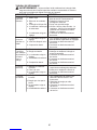
18
TROUBLE CAUSE REMEDY
Engine will not
start.
1. Engine flooded.
2. Fuel tank empty.
3. Spark plug not firing.
4. Fuel not reaching
carburetor.
5. Carburetor requires
adjustment.
1. See “Starting a Flooded Engine” in
Operation Section.
2. Fill tank with correct fuel mixture.
3. Install new spark plug.
4. Check for dirty fuel filter; replace.
Check for kinked or split fuel line;
repair or replace.
5. Contact an authorized service dealer.
Engine will
not idle
properly.
1. Carburetor requires
adjustment.
2. Crankshaft seals worn.
3. Compression low.
1. See “Carburetor Idle Speed Adjustment”
in Service and Adjustments Section.
2. Contact an authorized service dealer.
3. Contact an authorized service dealer.
1. Air filter dirty.
2. Spark plug fouled.
3. Carburetor requires
adjustment.
4. Carbon build-up on
muffler outlet screen.
5. Compression low.
Engine will not
accelerate,
lacks power,
or dies under
a load.
1. Clean or replace air filter.
2. Clean or replace plug
and regap.
3. Contact an authorized service dealer.
4. Contact an authorized service dealer.
5. Contact an authorized service dealer.
Engine
smokes
excessively.
1. Fuel mixture incorrect.
2. Air filter dirty.
3. Carburetor requires
adjustment.
1. Empty fuel tank and refill with
correct fuel mixture.
2. Clean or replace air filter.
3. Contact an authorized service dealer.
Engine runs
hot.
1. Fuel mixture incorrect.
2. Spark plug incorrect.
3. Carburetor requires
adjustment.
4. Carbon build-up on
muffler outlet screen.
1. See “Fueling Engine” in Operation
section.
2. Replace with correct spark plug.
3. Contact an authorized service dealer.
4. Contact an authorized service dealer.
WARNING: Always stop unit and disconnect spark plug before performing all of the
recommended remedies below except remedies that require operation of the unit.
TROUBLESHOOTING TABLE

19
LIMITED WARRANTY
Husqvarna Consumer Outdoor Products
N.A., Inc. (Husqvarna), warrants to the origi-
nal consumer purchaser that each new gasoline
tool or attachment is free from defects in materi-
al and workmanship and agrees to repair or re-
place under this warranty any defective gaso-
line product or attachment as follows from the
original date of purchase.
2 YEARS -- Parts and Labor, when used for
household purposes.
90 DAYS -- Parts and Labor, when used for
commercial, professional, or income producing
purposes.
30 DAYS -- Parts and Labor, if used for rental
purposes.
This warranty is not transferable and does not
cover damage or liability caused by improper
handling, improper maintenance or alteration, or
the use of accessories and/or attachments not
specifically recommended by Husqvarna for
this tool. This warranty does not cover tune--up,
spark plugs, filters, starter ropes, cutting line, or
rotating head parts that will wear and require re-
placement with reasonable use during the war-
ranty period. This warranty does not cover pre--
delivery setup or normal adjustments explained
in the instruction manual. This warranty does
not cover transportation costs.
In the event you have a claim under this warran-
ty, you must return the product to an authorized
service dealer.
Should you have any unanswered questions
concerning this warranty, please contact:
Husqvarna Consumer Outdoor Products
9335 Harris Corners Parkway
Charlotte, NC 28269
1--800--554--6723
In Canada, contact:
Husqvarna Consumer Outdoor Products
850 Matheson Blvd. West
Mississauga, Ontario L5V 0B4
giving the model number, serial number and
date of purchase of your product and the name
and address of the authorized dealer from
whom it was purchased.
THIS WARRANTY GIVES YOU SPECIFIC
LEGAL RIGHTS, AND YOU MAY HAVE OTH-
ER RIGHTS WHICH VARY FROM STATE TO
STATE.
NO CLAIMS FOR CONSEQUENTIAL OR
OTHER DAMAGES WILL BE ALLOWED,
AND THERE ARE NO OTHER EXPRESS
WARRANTIES EXCEPT THOSE EX-
PRESSLY STIPULATED HEREIN.
SOME STATES DO NOT ALLOW LIMITA-
TIONS ON HOW LONG AN IMPLIED WAR-
RANTY LASTS OR THE EXCLUSION OR
LIMITATIONS OF INCIDENTAL OR CONSE-
QUENTIAL DAMAGES, SO THE ABOVE LIM-
ITATIONS OR EXCLUSION MAY NOT APPLY
TO YOU.
This is a limited warranty within the meaning of
that term as defined in the Magnuson--Moss Act
of 1975.
The policy of Husqvarna is to continuously
improve its products. Therefore, Husqvarna
reserves the right to change, modify, or dis-
continue models, designs, specifications,
and accessories of all products at any time
without notice or obligation to any purchaser.

20
U.S. EPA / CALIFORNIA / ENVIRONMENT CANADA
EMISSION CONTROL WARRANTY STATEMENT
IMPORTANT: This product is compliant with U.S. EPA Phase 3 regulations for exhaust and evaporative
emissions. To ensure EPA Phase 3 compliance, we recommend using only genuine replacement parts. Use of
non-compliant replacement parts is a violation of federal law.
YOUR WARRANTY RIGHTS AND OBLIGATIONS: The U.S. Environmental Protection Agency, California Air
Resources Board, Environment Canada and Husqvarna Consumer Outdoor Products N.A., Inc. (HCOP) are
pleased to explain the emissions control system warranty on your year 2013 and later off-road engine. In
California, all small off-road engines must be designed, built, and equipped to meet the State’s stringent anti-
smog standards. HCOP must warrant the emission control system on your small off-road engine for the periods of
time listed below provided there has been no abuse, neglect, or improper maintenance of your small off-road
engine. Your emission control system includes parts such as the carburetor, the ignition system and the fuel tank,
line, and cap. Where a warrantable condition exists, HCOP will repair your small off-road engine at no cost to you.
Expenses covered under warranty include diagnosis, parts and labor.
MANUFACTURER’S WARRANTY COVERAGE: If any emissions related part on your engine (as listed under
Emissions Control Warranty Parts List) is defective or a defect in the materials or workmanship of the engine
causes the failure of such an emission related part, the part will be repaired or replaced by HCOP.
OWNER’S WARRANTY RESPONSIBILITIES: As the small off-road engine owner, you are responsible for the
performance of the required maintenance listed in your instruction manual. HCOP recommends that you retain all
receipts covering maintenance on your small off-road engine, but HCOP cannot deny warranty solely for the lack
of receipts or for your failure to ensure the performance of all scheduled maintenance. As the small off-road
engine owner, you should be aware that HCOP may deny you warranty coverage if your small off-road engine or
a part of it has failed due to abuse, neglect, improper maintenance, unapproved modifications, or the use of parts
not made or approved by the original equipment manufacturer. You are responsible for presenting your small off-
road engine to a HCOP authorized repair center as soon as a problem exists. Warranty repairs should be
completed in a reasonable amount of time, not to exceed 30 days. If you have any questions regarding your
warranty rights and responsibilities, you should contact your nearest authorized service center.
Please call HCOP at 1-800-487-5951 (USA) or 1-800-805-5523 (Canada) or send e-mail correspondence to
WARRANTY COMMENCEMENT DATE: The warranty period begins on the date the small off-road engine is
purchased.
LENGTH OF COVERAGE: This warranty shall be for a period of two years from the initial date of purchase, or
until the end of the product warranty (whichever is longer).
WHAT IS COVERED: REPAIR OR REPLACEMENT OF PARTS. Repair or replacement of any warranted part
will be performed at no charge to the owner at an approved HCOP servicing center. If you have any questions
regarding your warranty rights and responsibilities, you should contact your nearest authorized service center.
Please call HCOP at 1-800-487-5951 (USA) or 1-800-805-5523 (Canada) or send e-mail correspondence to
WARRANTY PERIOD: Any warranted part which is not scheduled for replacement as required maintenance, or
which is scheduled only for regular inspection to the effect of “repair or replace as necessary” shall be warranted
for 2 years. Any warranted part which is scheduled for replacement as required maintenance shall be warranted
for the period of time up to the first scheduled replacement point for that part.
DIAGNOSIS: The owner shall not be charged for diagnostic labor which leads to the determination that a
warranted part is defective if the diagnostic work is performed at an approved HCOP servicing center.
CONSEQUENTIAL DAMAGES: HCOP may be liable for damages to other engine components caused by the
failure of a warranted part still under warranty.
WHAT IS NOT COVERED: All failures caused by abuse, neglect, or improper maintenance are not covered.
ADD-ON OR MODIFIED PARTS: The use of add-on or modified parts can be grounds for disallowing a warranty
claim. HCOP is not liable to cover failures of warranted parts caused by the use of add-on or modified parts.
HOW TO FILE A CLAIM: If you have any questions regarding your warranty rights and responsibilities, you
should contact your nearest authorized HCOP service center.
Please call HCOP at 1-800-487-5951 (USA) or 1-800-805-5523 (Canada) or send e-mail correspondence to
WHERE TO GET WARRANTY SERVICE: Warranty services or repairs shall be provided at all HCOP service
centers. Please call HCOP at 1-800-487-5951 (USA) or 1-800-805-5523 (Canada) or send e-mail
correspondence to emis[email protected].
MAINTENANCE, REPLACEMENT AND REPAIR OF EMISSION RELATED PARTS: Any HCOP approved
replacement part used in the performance of any warranty maintenance or repair on emission related parts will be
provided without charge to the owner if the part is under warranty.
EMISSION CONTROL WARRANTY PARTS LIST: Carburetor, air filter (covered up to maintenance schedule),
ignition system: spark plug (covered up to maintenance schedule), ignition module, muffler including catalyst (if
equipped), fuel tank, line, and cap.
MAINTENANCE STATEMENT: The owner is responsible for the performance of all required maintenance as
defined in the instruction manual.
Page is loading ...
Page is loading ...
Page is loading ...
Page is loading ...
Page is loading ...
Page is loading ...
Page is loading ...
Page is loading ...
Page is loading ...
Page is loading ...
Page is loading ...
Page is loading ...
Page is loading ...
Page is loading ...
Page is loading ...
Page is loading ...
Page is loading ...
Page is loading ...
Page is loading ...
Page is loading ...
Page is loading ...
Page is loading ...
Page is loading ...
Page is loading ...
Page is loading ...
Page is loading ...
Page is loading ...
Page is loading ...
Page is loading ...
Page is loading ...
Page is loading ...
Page is loading ...
Page is loading ...
Page is loading ...
Page is loading ...
Page is loading ...
Page is loading ...
Page is loading ...
Page is loading ...
Page is loading ...
Page is loading ...
Page is loading ...
Page is loading ...
Page is loading ...
-
 1
1
-
 2
2
-
 3
3
-
 4
4
-
 5
5
-
 6
6
-
 7
7
-
 8
8
-
 9
9
-
 10
10
-
 11
11
-
 12
12
-
 13
13
-
 14
14
-
 15
15
-
 16
16
-
 17
17
-
 18
18
-
 19
19
-
 20
20
-
 21
21
-
 22
22
-
 23
23
-
 24
24
-
 25
25
-
 26
26
-
 27
27
-
 28
28
-
 29
29
-
 30
30
-
 31
31
-
 32
32
-
 33
33
-
 34
34
-
 35
35
-
 36
36
-
 37
37
-
 38
38
-
 39
39
-
 40
40
-
 41
41
-
 42
42
-
 43
43
-
 44
44
-
 45
45
-
 46
46
-
 47
47
-
 48
48
-
 49
49
-
 50
50
-
 51
51
-
 52
52
-
 53
53
-
 54
54
-
 55
55
-
 56
56
-
 57
57
-
 58
58
-
 59
59
-
 60
60
-
 61
61
-
 62
62
-
 63
63
-
 64
64


Ask a question and I''ll find the answer in the document
Finding information in a document is now easier with AI
in other languages
- français: Poulan Pro PP28RJ Manuel utilisateur
- español: Poulan Pro PP28RJ Manual de usuario
Related papers
Other documents
-
Weed Eater 530087645 User manual
-
-
Craftsman 358.798461 Owner's manual
-
-
-
-
-
-
PowerSmart PS4531 Operating instructions
-