Page is loading ...

Notice!
Although every effort has been made to insure that this manual is current
and accurate as of date of publication, no guarantee is given or implied
that this document is error free or accurate with regard to any specifica-
tion. TC Communications, Inc. reserves the right to change or modify
the contents of this manual at any time without prior notification.
© COPYRIGHT 1992-2007. ALL RIGHTS RESERVED.
MODEL:
S/N:
DATE:
TC Communications, Inc. 17881 Cartwright Road - Irvine, CA 92614
Tel: (949) 852-1972 Fax: (949) 852-1948 Web Site: www.tccomm.com Email: info@tccomm.com
TC2200R/S
MULTI-DROP (BUS)
FIBER OPTIC MODEM
User's Manual

- 2 -
TC2200R/S Bus
User's Manual
Rev. 2.2
Table of Contents
Chapter 1 - Overview ...................................................................................................3
Description.......................................................................................................................................... 3
Application Topologies...................................................................................................................... 4
LEDs, DIP Switches and Connectors.............................................................................................. 5
Internal SW1 DIP Switch Functions ................................................................................................ 6
Single-Master Units ..................................................................................................................... 6
Multi-Master Units (Optinal) ....................................................................................................... 7
External SW2 DIP Switch Functions ............................................................................................... 8
Pin Assignments and Connection ................................................................................................... 8
RS-422 & RS-485 Termination Resistors.....................................................................................10
Fiber Optic Specifications ..............................................................................................................10
Transmission Distances (typical) ............................................................................................10
Launch Power & Sensitivity .....................................................................................................10
Chapter 2 - Installation .............................................................................................. 11
Unpacking the Unit ..........................................................................................................................11
Equipment Location ........................................................................................................................11
Dry Contact Alarm Relay.................................................................................................................11
Power Supply ...................................................................................................................................11
Installation Procedure Summary ...................................................................................................11
Installation Example & RS-232 Virtual Connection ..............................................................12
Chapter 3 - Troubleshooting ...................................................................................... 13
General ..............................................................................................................................................13
All LEDs are Off................................................................................................................................13
Alarm LED .........................................................................................................................................13
Optic Cable Types............................................................................................................................13
Calculating the Loss on the Fiber .................................................................................................13
Chapter 4 - Bench Tests ............................................................................................ 14
General ..............................................................................................................................................14
Testing Considerations .............................................................................................................14
Bench Test With Built-In Signal Generator..................................................................................14
Optic Loopback Bench Test ...........................................................................................................15
Local Electrical Loopback Bench Test..........................................................................................16
Remote Loopback Bench Test .......................................................................................................17
Commonly Asked Questions..........................................................................................................18
Chapter 5 - Component Placement ............................................................................ 20
Chapter 6 - Specifications.......................................................................................... 21
Appendix A - DB25 to 2 RJ-11’s Adapter .................................................................... 22
Appendix B - Warranty............................................................................................... 23
Return Policy ....................................................................................................................................23
Warranty ............................................................................................................................................23

- 3 -
TC2200R/S Bus
User's Manual
Rev. 2.2
Chapter 1 - Overview
Description
The TC2200R/S and TC2201R/S are multi-drop fiber optic modems that convert electrical signals to fiber
optic signals (and vice-versa). At least one TC2200 (Master) unit and one TC2201 (Slave) unit are required
to communicate with each other. The Master unit is connected to a Host computer (or controller), while the
Slave unit can be connected to an RTU (Remote Terminal Unit), PLC (Programmable Logic Controller) or
any poll-response type device. Typical applications include SCADA, process control, traffic control and
energy management.
In a poll-response environment, the host controller broadcasts polling messages to every RTU. Because the
polling message is embedded with a specific RTU’s ID (or address), only the RTU with the correct ID
responds to the Master’s polling. The Master (TC2200) unit's function is to convert the electrical signals
(RS-232, RS-422 or RS-485) from the Host controller to fiber optic signals, then transmit the signals in both
bus directions to the Slaves, as illustrated in Figure 1.
The first Slave in the bus intercepts the Master's broadcast message and forwards it to its downstream Slave
unit. Each subsequent Slave forwards the broadcast message until it reaches the last Slave in the bus
(designated as the End Unit).
The Slave (TC2201) unit's function is similar to the Master's; it converts fiber optic signals from the Master
back into electrical signals (RS-232, RS-422 or RS-485) so that the RTU or PLC connected to the Slave
receives the polling message from the Host. The Slave unit then converts the electrical response signals
from the RTU or PLC to fiber optic signals, then transmits them back to the Host (via the Master) in both
bus directions, as illustrated in Figure 2.
Figure 1. Master Unit's Broadcast & Receive Directions
Figure 2. Slave Unit's Response & Receive Directions

- 4 -
TC2200R/S Bus
User's Manual
Rev. 2.2
Figure 3. Single Master Located at the End of a Bus
Figure 4. Single Master Located in the Middle of a Bus
Figure 5. Dual Masters Located at Each End of a Bus
Application Topologies
The optic signal transmitted to the right (or East) side of the unit is designated as the “A” direction, while
the optic signal transmitted to the left (or West) side of the unit is designated as the “B” direction.
Therefore, the optic transmitter A (labeled “TxA”) is always connected to the next unit’s optic receiver A
(labeled “RxA”). The same applies to the left (or "B") direction. Because the TC2200/2201 can transmit
to and receive from two directions, it allows for three different topology arrangements, as illustrated below:
Note: The Dual Master (optional) topology enables fault tolerance (similar to a self-healing function) in
many applications. If a fiber link becomes degraded or broken in this topology, the Host controller can
detect that the RTU is not responding to its broadcast message. When the controller's software is
configured for this type of fault detection, it will then re-route the broadcast message to the secondary
Master (through a secondary port), thereby reaching the lost Slave unit and RTU(s).

- 5 -
TC2200R/S Bus
User's Manual
Rev. 2.2
LEDs, DIP Switches and Connectors
Figure 6. TC2200/2201's Front Panel
Figure 7. TC2200/2201's Rear Panel
1 2
3
4
ON
RxB
TxA
RxA
TxB
1
2
3
4
RMTLB
D
I
S
A
L
M
LOC
L
B
S
I
G
G
E
N
BRD-1
BRD-2
RSP-1
RSP-2
MULTI-DROP MODEM
MASTER: (solidly lit) - Unit is configured as a Master
SLAVE : (solidly lit) - Unit is configured as a Slave
DTE : (solidly lit) - Electrical interface is configured as DTE
DCE : (solidly lit) - Electrical interface is configuraed as DCE
Rx-A : (solidly lit) - The optic signal received at "RxA"
is above the sensitivity threshold
SynA : (solidly lit) - Data packet received at optic "RxA"
is valid
Rx-B : (solidly lit) - The optic signal received at "RxB"
is above the sensitivity threshold
SynB : (solidly lit) - Data packet received at optic "RxB"
is valid
BRD-1: for TC2201- Broadcast msg (Ch1) from remote Master
for TC2200- Broadcast msg (Ch1) from local Host
BRD-2: for TC2201- Broadcast msg (Ch2) from remote Master
for TC2200- Broadcast msg (Ch2) from local Host
RSP-1: for TC2201- Response msg (CH1) from local RTU
for TC2200- Response msg (CH1) from remote Slave
RSP-2: for TC2201- Response msg (CH2) from local RTU
for TC2200- Response msg (CH2) from remote Slave
PWRA : (solidly lit) - The power source connected to
Power jack "A" is powering the unit
PWRB : (solidly lit) - The power source connected to
Power jack "B" is powering the unit
(Both PWRA & PWRB will light when
power redundancy is utilized)
Vcc : (solidly lit) - Operating voltage derrived from PWRA
and/or PWRB is valid
ALARM: (flashing) - Optic signal lost from "RxA" or "RxB"
- The Packet received is invalid
- The Anti-Streaming timer has expired
- The unit is in a diagnostic mode
TxA: Optic Transmitter "A"
RxB: Optic Receiver "B"
TxB: Optic Transmitter "B"
RxA: Optic Receiver "A"
SW1: Remote Loopback (for diagnostics)
SW2: Local Loopback (for diagnostics)
SW3: Signal Generator (for diagnostics)
SW4: Disable Alarm
MASTER
SLAVE
DCE
DTE
Rx-A
SynA
Rx-B
SynB
P
W
R
A
P
W
R
B
V
c
c
A
L
A
R
M

- 6 -
TC2200R/S Bus
User's Manual
Rev. 2.2
Internal SW1 DIP Switch Functions
The internal SW1 DIP switches are used for application setup. All units are configured and tested at the
factory and two are typically pre-labeled according their position in the bus (#1 is the left-end unit in the bus;
#2 is the right-end unit).
Single-Master Units
SW1_1 & SW1_2 disable the "RxA" & "RxB"
optic receivers when switched to the Left position.
These two switches should be set according to the
position of the unit in the bus. Typically, "RxA" is
disabled on the first unit (Master or Slave) and
"RxB" is disabled on the last unit (End unit). All
other units (between the first and last units in the
bus) should have SW1_1 & SW1_2 in the Right
position for normal multi-drop operation.
The Master unit (TC2200) and Slave unit (TC2201) are interchangeable by sliding SW1_3 to the left or right.
NOTE 1: For customers who purchased the TC2200s before February 1, 2006, follow the SW1_3 settings
for interchanging the Master and Slave units as shown on the dialog box above.
NOTE 2: For customers who purchased the TC2200s after February 1, 2006, the SW1_3 settings for
interchanging the Master and Slave units are reversed than the settings shown on the dialog box above.
To set the unit as a Master, set SW1_3 to the Left “On” position. To set it as a Slave unit, set SW1-3 to the
Right “Off” position. The front panel's "MASTER" or "SLAVE" LED will light to indicate which
configuration the unit has. This is true for all types of electrical interfaces.
If the TC2200/2201 has an RS-422 or RS-485 (or RS-530) interface, then the unit's DTE or DCE
configuration can be changed by flipping SW1_4 (left for DTE; right for DCE). If the TC2200/2201 has an
RS-232 interface, then the unit's DTE or DCE configuration can ONLY be changed by replacing the unit's
interface module (from the factory). The front panel's "DTE" or "DCE" LED will light to indicate which
configuration the unit has.
The TC2200/2201 has a built-in Anti-Streaming function. Anti-Streaming can prevent a defective RTU from
blocking out an entire response channel; once activated, the electrical signal from the defective RTU is
blocked and the entire response channel is disconnected from the Slave unit. This feature can be disabled
by sliding SW1_5 to the Right position.
SW1_6 on the internal DIP switch is not used and should be kept in the Right (Off) position.
SW1_7 & SW1_8 control the RS-485 transition timer setup. For RS-232 and RS-422 interfaces, these
switches should be kept in the Right (Off) position. For a 2-wire or 4-wire RS-485 interface, the electrical
signal bus will automatically transition to high impedance after transmitting. These two switches establish
the duration period(after the last bit is transmitted) before the RS-485 driver transitions to the high-impedance
receiver mode. The transition timer should be set according to the following table (Default = both Off):
Figure 8. RS-485 Transition Timer Setup Table
Baud SW1_8 SW1_7 SW1_6
9600
19.2K
38.4K & up
On Off Not Used
Off On Not Used
On On Not Used

- 7 -
TC2200R/S Bus
User's Manual
Rev. 2.2
Multi-Master Units
If the units were ordered for a Multi-Master
Multi-Drop application (optional), the following
information applies to their configuration. The
Multi-Master units are (by default) DCE de-
vices. The internal SW1 DIP switch functions
and some features for Multi-Master units differ
slightly from Single-Master models.
SW1_1 & SW1_2 disable the "RxA" & "RxB" optic receivers when switched to the Left position. These
two switches should be set according to the position of the unit in the bus. Typically, "RxA" is disabled on
the first unit (Master or Slave) and "RxB" is disabled on the last unit (End unit). All other units (between
the first and last units in the bus) should have SW1_1 & SW1_2 in the Right position for normal multi-drop
operation.
The Master unit (TC2200) and Slave unit (TC2201) are interchangeable by sliding SW1_3 to the Left (Slave)
or Right (Master) position. The front panel's "MASTER" or "SLAVE" LED will light to indicate which
configuration the unit is utilizing. The Auto-Master Mode allows each unit to temporarily act as a Master unit
until the attached device stops transmitting for a predetermined amount of time (based on the baud switch
settings of SW1_7 & SW1_8).
The TC2200/2201 has a built-in Anti-Streaming function. Anti-Streaming can prevent a defective RTU from
blocking out an entire response channel; once activated, the electrical signal from the defective RTU is
blocked and the entire response channel is disconnected from the Slave unit. This feature can be disabled
by sliding SW1_5 to the Right position.
SW1_6 on the internal DIP switch is not used and should be kept in the Right (Off) position.
SW1_7 & SW1_8 control the RS-485 transition timer setup and the Master/Slave transition time. For a 2-
wire or 4-wire RS-485 interface, the electrical signal bus will automatically transition to high impedance after
transmitting. These two switches establish the duration period (after the last bit is transmitted) before the
RS-485 driver transitions to the high-impedance receiver mode.
The transition timer also establishes the interval of time that Master unit “holds” the bus (after the last data
bit is received from the local RTU) before automatically transitioning back into the Slave mode. The
transition timer should be set according to the following table (Default = both Off):
Figure 9. Transition Timer Setup Table
Baud SW1_8 SW1_7 SW1_6
9600
19.2K
38.4K & up
On Off Not Used
Off On Not Used
On On Not Used

- 8 -
TC2200R/S Bus
User's Manual
Rev. 2.2
External SW2 DIP Switch Functions
The external DIP switches (located on the front panel) are
used for diagnostic testing. When SW2_1, SW2_2 or
SW2_3 are in the Down position, the "ALARM" LED will
blink, indicating an abnormal condition. During normal
operation, all switches should be kept in the Up position.
SW2_1 (RMTLB): When this switch is in the Down position, the composite optical signal is received and
decoded, then looped back to the transmitter for diagnostic testing.
SW2_2 (LOCLB): When this switch is in the Down position, the electrical signal received (on pins 2 & 4
for an RS-232 interface) is looped back internally (to pins 3 & 5 for an RS-232 interface) for diagnostic
testing.
SW2_3 (SIG GEN): The TC2200/2201 has a built-in signal generator. By sliding this switch to the Down
position, a slow-rate pulse signal of logic "highs" and "lows" will be sent through the fiber to all units in the
bus, simulating a broadcast or response message. The "BRD" LEDs on the Master and "RSP" LEDs on the
Slaves will flash, indicating transmission & receipt of the other's signal.
SW2_4 (DIS ALARM): When this switch is in the Down position, the audio alarm buzzer and dry contact
alarm relay switch are disabled.
Pin Assignments and Connection
The DB25 connector on the rear panel of the TC2200/2201 provides for the connection of the user’s RS-
232, RS-422 or RS-485 devices. The pin assignments for each type of interface are illustrated in the diagrams
that follow.
For units with an RS-232 interface, two separate channels are provided for handshaking signals or the
connection of an additional device (this additional channel is not present on Multi-Master units). Pins 2 &
4 are inputs while pins 3 & 5 are outputs.
Figure 10. RS-232 Pin Assignments & Connection Diagram
1
2
3
4
ON
1
2
3
4
RMTLB (Remote Loopback)
D
I
S
A
L
A
R
M
(
D
i
s
a
b
l
e
A
l
a
r
m
)
LOCLB (Local Loopback
)
S
I
G
G
e
n
e
r
a
l
(
S
i
g
n
a
l
G
e
n
e
r
a
t
o
r
)

- 9 -
TC2200R/S Bus
User's Manual
Rev. 2.2
Figure 11. 2-wire RS-485 Connection/Logic Diagram
For RS-422 and RS-485 4-wire interfaces, pins 2(-) & 14(+) are inputs while pins 3(-) & 16(+) are outputs.
Figure 12. 4-wire RS-422/RS-485 Connection/Logic Diagram
For 2-wire RS-485 interfaces, pins 3(-) & 16(+) are input/outputs.

- 10 -
TC2200R/S Bus
User's Manual
Rev. 2.2
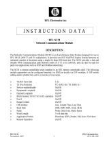
RS-422 & RS-485 Termination Resistors
A termination resistor is usually necessary for RS-422 and RS-485 applications. Without proper termina-
tion, the error rate of data transmission may be high due to an "echo" effect on the electrical connection.
With the addition of a termination resistor at the beginning or end of the electrical bus, this echo effect is
greatly reduced. The termination resistors are 100 to 130 ohm resistors located inside the TC2200/2201.
Two jumpers, located on the Interface Module at board locations "W1" & "W5," control the termination
resistance on each unit (factory default = installed). "W5" controls the resistance for the unit's receiver,
while "W1" controls the transmitter's resistance. Proper line termination is usually accomplished by
leaving the “W5” jumper installed at both ends of the link. There is no termination resistor required for RS-
232 applications.
Figure 13. Termination Resistor Locations
Fiber Optic Specifications
Transmission Distances (typical)
The TC2200 and TC2201 are compatible with all popular sizes and types of fiber. Transmission distances
up to 3km* are typical over Multimode fiber at 850nm and 4km* at 1310nm. Distances to 30km* are typical
over Single Mode fiber at 1310nm.
Launch Power & Sensitivity
Transmitter: LED/ELED; typical Launch Power - -20dBm* (850nm/1310nm MM, @62.5/125µm)
-16dBm* (1310nm Single Mode, @9/125µm)
Receiver: PIN Diode; typical Sensitivity - -36dBm* (850nm/1310nm MM, @62.5/125µm)
-36dBm* (1310nm Single Mode, @9/125µm)
*Launch power, sensitivity & distance are listed for reference only. These numbers may vary.
TB3
Female DB25
TB2 TB1
1 2 3 4
TxB TxARxA RxB
on
SW1
SW2
8
7
6
5
4
3
2
1
TC2200R/S
or
TC2201R/S
W1: (Installed)
Terminates pins 2 & 14 W5: (Installed)
Terminates pins 3 & 16
INTERFACE SIMM MODULE

- 11 -
TC2200R/S Bus
User's Manual
Rev. 2.2
Chapter 2 - Installation
Unpacking the Unit
Before unpacking any equipment, inspect all shipping containers for evidence of external damage caused
during transportation. The equipment should also be inspected for damage after it is removed from the
container(s). Claims concerning shipping damage should be made directly to the pertinent shipping agencies.
Any discrepancies should be reported immediately to the Customer Service Department at TC Communi-
cations, Inc.
Equipment Location
The TC2200/2201 should be located in an area that provides adequate light, work space and ventilation.
Avoid locating it next to any equipment that may produce electrical interference or strong magnetic fields,
such as elevator shafts and heavy duty power supplies. As with any electronic equipment, keep the unit from
excessive moisture, heat, vibration and freezing temperatures.
Dry Contact Alarm Relay
A terminal block connector at the rear panel provides for the Dry Contact Alarm Relay Normally in the
OPEN position, any alarm condition will force the switch to a CLOSED position. This relay can be used in
conjunction with an external device (such as an RTU) to signal an alarm condition to the Host.
Power Supply
Typically, a 9V to 12V DC power supply @650mA is adequate for the TC2200/2201. The power plug is a
terminal block connector with positive & negative polarity indicated on the rear panel of the unit. Two
connectors, labeled "PWR A" & "PWR B" are provided for a built-in power redundancy feature. While only
one connection is required to power the unit, both connectors can be used simultaneously. When power
redundancy is utilized, both power "A" & "B" share the load. If one power supply fails, the other will take
over the full load. Alternate power sources are available as an option (see Chapter 6 - Specifications).
Installation Procedure Summary
The TC2200 and TC2201 are designed for quick and easy installation. Before installing, however, make sure
all DIP switches on the front panel are in the Up position and double-check the polarity at the DC power's
terminal block connector(s).
A. Connect the Host's RS-232, RS-422 or RS-485 signal (see pages 8 & 9 for pin assignments) to the
TC2200 (Master) unit's DB25 connector.
B. Configure the Master unit's internal DIP switch (see pages 6 & 7) and connect power to the Master unit.
Run an Optic Loopback Test and Local Electrical Loopback Test (see pages 15 & 16).
C. Connect the RTU's RS-232, RS-422 or RS-485 signal to the TC2201 (Slave) unit's DB25 connector.
D. Configure the End Unit's internal DIP switch (see pages 7 & 8) and connect power to the Slave unit.
Run an Optic Loopback, Local Loopback and Remote Loopback Test (see pages 15, 16 & 17).
E. Configure and connect additional Slave units into the bus (see page 4 for application topologies). Run
an Optic Loopback, Local Loopback and Remote Loopback Test for each additional unit installed.
F. Verify System Integrity:
At Master and Slave units, check "Rx-A," "Rx-B," "SynA" and "SynB" LED indicators.
Verify and record the optical cable loss for each link in the application after installation is complete. This
reading will both verify the integrity of the circuit and provide a benchmark for future troubleshooting efforts
(see Chapter 3 - Troubleshooting).

- 12 -
TC2200R/S Bus
User's Manual
Rev. 2.2
Installation Example & RS-232 Virtual Connection
To install a multi-drop bus topology, follow the example below. The SCADA Host controller is connected
to the Master unit (TC2200), and four RTUs are connected to Slave units (TC2201). Notice the fiber cable
from each unit's optic "TxA" (on the right side) is connected to the next unit's optic "RxA," while each unit's
optic "TxB" (on the left side) is connected to the next unit's optic "RxB." In this example, the "RxA" on
the Master unit and "RxB" on the last Slave unit (End unit) should be disabled.
Figure 14. RS-232 Installation Example
Figure 15. RS-232 Virtual Connection Diagram
Note 1: The internal DIP Switch functions for Multi-Master units differ slightly from the Single Master units shown (see page 7).
*Note 2: For units purchased after February 1, 2006, the settings of SW1_3 are reversed than for the settings shown on the
diagrams above. ; Set SW1_3 to the Left (On) for Master and to the Right (Off) for Slave, see notes1 & 2 on page 6. (Units
bought prior to February 1, 2006 hold the same settings as shown above)
TxA TxA TxA TxA
TxA
BRD BRD BRD RSP
RSP CTS CTS CTS CTS
CTS RSP RSP RSP BRD
BRD RTS RTS RTS RTS
RTS
RTU RTU RTU
RTU
5 5 5 5
53 3 3 3
34 4 4 4
42 2 2 2
2
RxA RxA RxA
RxA
RxA RxB RxB RxB
RxB
RxB TxB TxB TxB
TxB
TxB

- 13 -
TC2200R/S Bus
User's Manual
Rev. 2.2
Chapter 3 - Troubleshooting
General
Alarm conditions occur whenever an optical problem or "fault" condition is detected by the TC2200/2201.
Under normal operation, all LEDs should be lit, with the exception of either the "DTE" or "DCE" and
"ALARM" LEDs. The "BRD" and "RSP" LEDs will only light when there is activity on the bus.
All LEDs are Off
If no LEDs are lit on the unit, check the DC power supply, terminal block connector plug, and/or the power
source. If the problem persists, contact the Technical Support Department at TC Communications, Inc.
Alarm LED
When an alarm condition is detected, the Alarm LED will flash rapidly and one or more additional LED will
flash. The following fault conditions will cause the alarm to be triggered:
1. Optic signal lost from "RxA" or "RxB."
2. Optic signal is marginal, which causes invalid data packets to be received; either the "SynA" or "SynB"
LED will be flashing.
3. Optic overdrive can cause the "SynA" or "SynB" LED to flash while optic "A" and/or "B" still receives
a valid signal.
4. One or more of the front panel's DIP switches is in the Down position.
5. The Anti-Streaming function has been activated.
Optic Cable Types
Conventionally, fiber optic cable with yellow-colored insulation is used for Single Mode applications; gray
or orange-colored insulated cable is for Multimode use. If Multimode cable is used in a Single Mode
application, the test results could be erroneous and confusing.
Calculating the Loss on the Fiber
The fiber optic link and/or connectors are frequently the source of various problems. Check out the
connectors and the integrity of the link first. Ideally, the link should be calibrated for total loss after the
installation has been completed. This will accomplish two things: (1) it will verify that the total loss of the
link is within the loss budget of the device and (2) it will provide a benchmark for future testing. For example,
a system that has been tested as having 6dB total loss when installed and suddenly tests out as having a loss
of 10dB probably has a connector or link problem.
*These numbers are listed for reference only. We recommend an OTDR reading be used to determine actual link loss.
These are the reference values we use to calculate the loss on the fiber:
Multimode 850nm :3 dB loss per km on 62.5/125µm cable*
Multimode 1310nm :2 dB loss per km on 62.5/125µm cable*
Single Mode 1310nm :0.5 dB loss per km on 9/125µm cable*
Single Mode 1550nm :0.25 dB loss per km on 9/125µm cable*

- 14 -
TC2200R/S Bus
User's Manual
Rev. 2.2
Chapter 4 - Bench Tests
General
It is highly recommended to conduct bench tests before actual installation. Bench testing allows the user to
become familiar with all the functions and features of the TC2200/2201 in a controlled environment.
Knowledge of these functions and features will ease installation and troubleshooting efforts later on.
Testing Considerations
You may substitute the SCADA Host controller with a BERT (Bit Error Rate Tester) test set to generate
a simulated RS-232, RS-422 or RS-485 signal. For each test, double-check the LED indicators and DIP
switch settings on all units.
The Anti-Streaming function applies to both the Data (pin 2 on the DB25's RS-232 interface) and RTS signals
(pin 4 on the DB25's RS-232 interface) from the RTU. The Anti-Streaming function can be disabled by sliding
SW5 on the internal DIP switch to the Left position.
The "BRD" and "RSP" LEDs flash at the rate of the transmitted or received data. If you are sending bus data,
the LEDs will only flash when data is present. Under this condition they may appear dim or even unlit at times.
If this is the case, you may want to increase your data rate and send it in a continuous data format while
testing.
Bench Test With Built-In Signal Generator
The TC2200 (Master) has a built-in signal generator to simulate a broadcast message from a SCADA Host,
while the TC2201 (Slave) has a signal generator to simulate an RTU's response message. The built-in signal
generator is a pulse signal indicated by a blinking LED. The flash rate is intentionally reduced for easy visual
confirmation.
1. Set up the bench test as shown in Figure 16. At the Master unit, turn on the "SIG-GEN" by sliding SW2_3
(on the front panel) downward. The "BRD-1" and "BRD-2" LEDs on the TC2200 (Master) should start
blinking. Likewise, the "BRD-1" and "BRD-2" LEDs on all of the TC2201 (Slave) units should also blink,
indicating receipt of the Master's broadcast signal.
2. At any Slave, turn on the "SIG-GEN" by sliding SW2_3 (on the front panel) downward. The "RSP-1"
and "RSP-2" LEDs should start blinking. Verify that the Master's "RSP-1" and "RSP-2" LEDs also blink,
indicating receipt of the Slave's simulated response.
Figure 16. Bench Test Connection Diagram
TxA TxA TxA TxATxA RxA RxA RxA RxARxA RxB RxB RxB RxB
RxB TxB TxB TxB TxB
TxB
Note 1: To perform this test on Multi-Master units, one unit must be configured as a dedicated Master (by sliding SW1_3 to the
Right) and all other units must be configured as dedicated Slaves (by sliding SW1_3 to the Left & SW1_4 to the Right).
*Note 2: For units purchased after February 1, 2006, the settings of SW1_3 are reversed than for the settings shown on the
diagrams above. ; Set SW1_3 to the Left (On) for Master and to the Right (Off) for Slave, see notes1 & 2 on page 6. (Units
bought prior to February 1, 2006 hold the same settings as shown above). The internal DIP Switch functions for Multi-Master
units differ slightly from the Single Master units shown (see page 7).

- 15 -
TC2200R/S Bus
User's Manual
Rev. 2.2
Optic Loopback Bench Test
Purpose: To test the broadcast (or response) and receive capabilities of a Master or Slave unit
without any other units attached.
Equipment
Requirements: One (1) Bit Error Rate Test (BERT) Set with appropriate interface module.
One (1) optical jumper cable (patch cord) with appropriate connectors.
Procedure: Set up the bench test as shown in Figure 17. To test the "TxB" to "RxA" loop, connect
an optic patch cord from optic "TxB" to optic "RxA." Set the unit's internal DIP switch
SW1_2 to the Left position (to disable "RxB"). Connect a BERT tester to the DB25
connector. Set the tester up as a DTE or DCE device (the opposite of the unit's lit "DCE"
or "DTE" LED indicator). The BERT tester should indicate a "SYNC" signal.
Remove the patch cord from "TxB" and "RxA" and switch SW1_2 back to the Right
position. The "SYNC" light on the tester should turn "Off."
To test the "TxA" to "RxB" loop, repeat the steps above with an optic patch cord from
"TxA" to "RxB." Set internal DIP switch SW1_1 to the Left position (to disable "RxA").
The BERT tester should indicate a "SYNC" signal. After testing is complete, return all
switches to their normal operating positions.
Figure 17. Optic Loopback Bench Test Connection Diagram

- 16 -
TC2200R/S Bus
User's Manual
Rev. 2.2
Local Electrical Loopback Bench Test
Purpose: To verify the DB25's cable connections, the electrical interface driver, and the receiver's
Integrated Circuitry.
Equipment
Requirements: One (1) Bit Error Rate Test (BERT) Set with appropriate interface module.
Procedure: Set up the bench test as shown in Figure 18. Set SW2_2 ("LOCLB" on the front panel)
to the Down position and the "ALARM" LED should start flashing. Set the tester up as
a DTE or DCE device (the opposite of the unit's lit "DCE" or "DTE" LED indicator). The
"BRD-1" & "BRD-2" and "RSP-1" & "RSP-2" LEDs should be dimly lit, showing the
status of the looped signal. The BERT tester should indicate a "SYNC" signal. This test
should be performed on each individual unit in the application.
Figure 18. Local Electrical Loopback Bench Test Connection Diagram

- 17 -
TC2200R/S Bus
User's Manual
Rev. 2.2
Remote Loopback Bench Test
Purpose: To test the Slave unit's optic functions and LED indicators and to verify the integrity of
the fiber optic link. When installing new Slave units in a network, a Remote Loopback
test should be performed between each individual Slave and the Master unit (one at a
time). This will verify the integrity of the system.
Equipment
Requirements: One (1) Bit Error Rate Test (BERT) Set with appropriate interface module.
At least two (2) optical jumper cables (patch cords) with appropriate connectors.
Procedure: Set up the bench test as shown in Figure 19. Make sure to set the internal DIP switches
accordingly for each unit. At the front panel of the Slave unit to be tested, slide SW2_1
(RMTLB) to the Down position. Set the tester up as a DTE or DCE device (the opposite
of the Master unit's lit "DCE" or "DTE" LED indicator). The "BRD-1" & "BRD-2" and
"RSP-1" & "RSP-2" LEDs should be dimly lit, showing the status of the looped signal.
The BERT tester (connected to the Master) should indicate a "SYNC" signal.
Figure 19. Remote Loopback Bench Test Connection Diagram

- 18 -
TC2200R/S Bus
User's Manual
Rev. 2.2
Commonly Asked Questions
1. Where is the best place to begin installation for a bus topology application ?
Ans: Begin with the Master unit. The first priority is to get familiar with the functions of DIP switches
and LEDs.
2. How do I know if the optic link is open or closed ?
Ans: The "SynA" and/or "SynB" LEDs on the affected units will flash if the associated link is not
closed.
3. What direction is the optic signal traveling in ?
Ans: The fiber signal that transmits to the East side of the unit is designated as "A", which means from
one unit's optic "TxA" to the next unit's optic "RxA." The fiber signal that transmits to the West
side of the unit is designated as "B," which means from one unit's optic "TxB" to the next unit's
optic "RxB."
4. What do the front panel's "BRD" & "RSP" LEDs mean ?
Ans: The "BRD-1" & "BRD-2" stand for Broadcast Data. They are the signals from the SCADA Host
(connected to the Master) to be transmitted (or broadcasted) to the Slaves. The "BRD-1" &
"BRD-2" LEDs on the Master unit reflect the incoming signal status of the DB25's connector pins
2 & 4 (for an RS-232 interface) from the SCADA host. On the Slave units, the "BRD-1" & "BRD-
2" are the received broadcast signals originating from the SCADA host.
The "RSP-1" & "RSP-2" stand for Response Data. On the Slave unit, they are the response
signals from the local RTU to be transmitted to the Master. The "RSP-1" & "RSP-2" LEDs on
the Slave unit reflect the outgoing signal status of the DB25's connector pins 3 & 5 (for an RS-
232 interface) from the local RTU. On the Master, the "RSP-1" & "RSP-2" are the received
response signals originating from the RTU.
The following tables explain the definitions of each "BRD" and "RSP" LED for Master & Slave
units for an RS-232 interface:
Figure 20. "BRD" and "RSP" LED Definitions for an RS-232 Interface

- 19 -
TC2200R/S Bus
User's Manual
Rev. 2.2
5. What is the built-in signal generator and how is it used ?
Ans: By sliding SW2_3 ("SIG GEN" on the front panel) to the Down position, a pulse signal will be
generated to simulate an incoming signal on the DB25's connector pins 2 & 4 (for an RS-232
interface). In effect, this pulse signal is a simulated broadcast signal from the SCADA host,
which will travel through the fiber to each Slave in the bus. This function is very useful for
troubleshooting and verifying network integrity. The slow pulse rate of the LEDs can be easily
confirmed at any Slave location.
6. What is the difference between the front panel's "Rx-A" and "SynA" LEDs ?
Ans: "Rx-A" indicates the receiving optical signal strength. When the "RxA" optic signal is above the
sensitivity threshold (typically from -33dBm to -36dBm) the "Rx-A" LED will light (solid). A
marginal or fault condition causes it to flash. In some cases, the "RxA" optic signal is above the
sensitivity threshold but is of poor quality. This will result in an invalid data packet being
received, causing the "SynA" LED to flash.
The possible fault conditions could be one of the following:
A. Received optic signal's power is marginal (at the borderline of the sensitivity threshold).
B. Receiver is being overdriven (optic signal strength is too strong).
C. Multimode cable is used on a Single Mode unit and causes the receiver to be overdriven.
D. Optic cable is cross-connected with another vendor's product and the TC2200/2201 can not
recognize the data packet being transmitted.
The "SynA" LED lights (solid) when the data packet being received at optic "RxA" is validated.
An invalid data packet will cause the "SynA" LED to flash.
The same applies to the "Rx-B" and "SynB" LEDs for the B-Link.

- 20 -
TC2200R/S Bus
User's Manual
Rev. 2.2
The TC2200/2201 is equipped with multiple DIP switches for application setup and Panel LEDs to indicate
the status of electrical and optical signals. These features can ease installation and facilitate troubleshooting.
The following diagram depicts the board locations of several key components.
Figure 21. TC2200/2201 Component Placement Diagram
Chapter 5 - Component Placement
SW2
1/23