CrimeStopper RS1-G5 Installation guide
- Category
- Remote starters
- Type
- Installation guide
This manual is also suitable for

* Optional ‘OL-HRN-RS’ T-harnesses available. See vehicle compatibility at www.wiresheet.com.
** 4 = The function is supported via the data ports. Conrm vehicle support in interface module install guide.
*** Function auto-detected during VEHICLE LEARN procedure - SEE OTHER SIDE OF THIS SHEET
Default function is capitalized and underlined
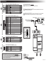
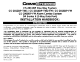
RSX-G6 Wire Diagram
Push-Button Status Light
(P/N: AU-LED-PB2)
Status Light
Valet / Programming
Button
A
BLACK 6 PIN HIGH CURRENT POWER HARNESS (P/N: H-RS6F*)
PIN POL. COLOR FUNCTION DATA**
1(+) PINK/WHITE IGNITION / Accessory / Start (Prog. - Feature #2) - INPUT/OUTPUT*** 4
2(+) BROWN START - INPUT/OUTPUT 4
3(+) GRAY ACCESSORY / Ignition / Start (Prog. - Feature #2) - INPUT/OUTPUT*** 4
4(+) RED Feed For GRAY(A3) / BROWN(A2) / PINK/WHITE(A1) - INPUT (30A Fused)
5(+) RED System Power - INPUT (30A - Fused)
6(+) PINK IGNITION / Accessory / Start - INPUT/OUTPUT*** 4
4
36
1ETEMPERATURE SENSOR - DO NOT COVER
(For high/low temp auto start and for tachless low temp crank extender)
C
RED 3 PIN DOOR LOCK/UNLOCK HARNESS (P/N: DLP-N3)
PIN POL. COLOR FUNCTION DATA**
1(-) GREEN Lock Pulse - OUTPUT (250ma) 4
2(+) EMPTY PIN Constant +12V Supply To Plug-in Door Lock Adapters - OUTPUT (500ma)
3(-) BLUE Unlock Pulse - OUTPUT (250ma) 4
3
1
FANTENNA / STATUS LIGHT / VALET PORT - Supports any compatible plug-in antennas or push-
button status light (P/N: AU-LED-PB2)
D
RED 3 PIN REMOTE START HARNESS (P/N: H-RS3A)
PIN POL. COLOR FUNCTION (RED PORT) DATA**
1(-) ORANGE/WHITE Status (Prog. - Feature #11) - OUTPUT (250ma) 4
2(+) RED Constant +12V Supply For Relays Or Modules - OUTPUT (500ma)
3(-) BLUE/ORANGE Start (Prog. Feature #12) - OUTPUT (250ma) 4
3
1
AB
C D GFE
Starter Interrupt/Anti-Grind Relay
(P/N: AU-SOCKET - Optional)
Starter
Ign. Switch
WHITE
RED
Cut Starter Wire
ORANGE
OR
GGREEN & BLACK DATA PORTS - For Telematics / Data Sensor (Shock, Tilt, etc) / Vehicle Interface
Module. (DBI & iDatalink protocols supported on both ports - see ‘Vehicle Learn’ or feature #3)
B
WHITE 14 PIN MAIN INPUT/OUTPUT HARNESS (P/N: H-RS14F)
PIN POL. COLOR FUNCTION DATA**
1(-) YELLOW/BLACK Status/GWR (Prog. Feature #10) - OUTPUT (500ma)
2(-) WHITE/BLACK Light Flash - OUTPUT (250ma) 4
3(-) BROWN Trunk Release (Prog. Feature #20) - OUTPUT (250ma) 4
4(-) ORANGE/BLACK OEM Alarm Disarm (Prog. - Feature #13) - OUTPUT (250ma) 4
5(-) GRAY Hood Trigger - INPUT 4
6(-) RED/WHITE Tach Pulse Input (coil or injector) - INPUT 4
7(-) PINK Glow Plug (Diesel) / Door Trigger (MT Mode Required) - INPUT 4
8(-) GREEN RS Activation (Automatic) / Parking Brake (MT Mode Required) - INPUT 4
9EMPTY
10 (-) ORANGE OEM Alarm Arm (Prog. - Feature #13) - OUTPUT (250ma) 4
11 (-) BLACK System Ground - INPUT
12 (-) YELLOW Horn Honk (Prog. - Feature #27 - 29) - OUTPUT (1A)
13 (+) VIOLET Brake Pedal RS Shutdown - INPUT 4
14 (+) WHITE Light Flash - OUTPUT (10A Fused) 4
18
714
Tech Support
Phone: 800-921-TECH (8324)
Web: OmegaDealer.com
FB dealer group: Facebook.com/groups/crimestopperinsight/
Corporate Site / Product Info: CrimeStopper.com
QIM_RSX-G6_20210610

TIP: You can program features via your computer with Omega Weblink.
Visit www.OmegaWeblink.com to learn more.
RSX-G6 QUICK REFERENCE
PROGRAMMING GUIDE (FOR FIRMWARE v1.0)
visit www.OmegaWeblink.com to get the latest firmware
visit www.OmegaDealer.com to download a complete guide
Features Chart
1. Enter feture programming (DO NOT SELECT ANY FEATURES).
2. Press LOCK + UNLOCK (or press BRAKE x 5)
- 1-button/2-button models: Press the START button 5 times
- You will get5 light ashes to indicate reset & exit programming.
Features Reset
Scan To Download
the full installation
guide from
OmegaDealer.com!
(login required)
Copyright 2021 Omega Research & Development Technologies, Inc. QIM_RSX-G6_20210610
LED Flashes/Chirps Alarm Quick Test Zone Violation Recall
1Sensor Full Trigger -
2 Hood Hood
3 Door Door
4Sensor Warning Sensor Port Trigger
LED Flashes Violated Zone
1Brake pedal pressed
2 Hood opened
3System in Valet Mode
43D sensor detected vehicle motion while cranking
5Engine running not detected
6Received engine stop command (remote, telematics, etc.)
7MT reservation mode not set
8 Run time expired
9Low vehicle battery voltage detected
1. Turn the ignition key “ON” (do not start).
2. Press the valet button 5 times within 5 seconds of step 1.
- The horn will chirp 5 times and the Parking Lights will ash 5 times
3. Press the valet button equal to the desired feature’s number.
- The horn will chirp once for every buttomn press.
- Once the desired button presses are complete the horn will chirp to conrm the chossen feature
(long chirp=10 short chirp=1, example: 2 long chirps followed by 5 short chirps equals feature 25).
4. Press the transmitter button (or brake pedal) to select the desired setting.
- 1-BUTTON MODELS: Change the feature by pressing the transmitter button OR brake pedal the same equal to the
desired setting. Complete all presses before hearing any chirps.
- The siren/horn will chirp equal to the selected setting.
5. Repeat steps 3 & 4 at this time IF you wish to change additional features.
6. Turn the ignition key “OFF” to exit programming.
- NOTE: The system will exit automatically at any time after 10 seconds of no activity.
Perform Vehicle Learn (US patent #10,151,289)
Programming Features Manually
Tach Wire Signal Learn
Zone Violation Recall: To diagnose alarm triggers, disarm/unlock the alarm with the remote and the status LED will
ash to indicate which zone(s) were triggered last. Turn the ignition key “ON” to clear alarm trigger memory.
If remote start fails to activate, the system will ash the parking lights, and ash the status LED to indicate
the cause. If remote start shuts down prematurely after successfully starting, you can recall the violation by putting
the system in valet mode (turn ignition ON and hold the valet button for 5+ seconds). Before the status LED turns on
(system in valet mode), the LED will ash to indicate any violated zones.
Programming Transmitters
Alarm Diagnostics
Remote Start Diagnostics
When utilizing the tach wire circuit for engine detection, the vehicle’s tach signal must be learned. Tach signal is learned
during Vehicle Learn and usually does not have to be relearned. Using either method below will automatically change
Installer Feature #1 to ‘Tach Wire’. If a valid tach signal is not detected, the system will not switch to ‘Tach Wire’ mode.
METHOD 1:
Perform Vehicle Learn - If a tach wire is connected, ‘tach wire’ mode will be selected and the signal auto-learned.
METHOD 2:
1. Turn the ignition key “ON”.
2. Press the brake pedal 5 times within 5 seconds of step 1.
- The siren/horn will chirp 5 times.
3. Start the engine.
- The status LED will turn on when it has learned the tach signal. If not, check tach wire & try again.
4. Press the valet button to resample the tach signal if needed. If the engine has a high idle at startup, allow the idle to
“settle” around 700 RPM before resampling.
- The status light will ash o then back on when the signal has been resampled.
5. Turn the ignition key “OFF”.
METHOD 3:
6. Start the engine with the ignition key.
7. Press & hold the brake pedal.
8. Press & release the valet button.
- The siren/horn will chirp 5 times.
- The status LED will turn on when it has learned the tach signal. If not, check tach wire & try again.
9. Turn the ignition key “OFF” or release the brake pedal to exit.
Vehicle Learn is the ultimate time saver and remote start conguration tool. It congures most
install-critical features to match vehicle requirements.
IT’S FASTER THAN PROGRAMMING EVEN ONE FEATURE MANUALLY OR ON YOUR PC!
Vehicle Learn Will:
• Automatically congure IGNITION, ACCESSORY, AND START circuits to match the vehicle.
• Let you quickly choose crank delay (NOTE: wait-to-start via data is always honored)
• Sample crank time for crank averaging (tachless modes only).
• Auto-detect engine running method: Data-tach, tach wire (will also tach learn), or tachless mode.
• Auto-detect data port protocols
Before You Begin:
• Make all wire connections
• Connect any accessories/modules to the data ports.
Make sure any interface module/bypass kit is in “DATA MODE” and programmed to the vehicle.
• If installing on a Manual Transmission vehicle, change feature #6 to desired setup process.
Connect the GREEN wire to the vehicles parking brake and set the parking brake.
Vehicle Learn Procedure:
1. Turn the ignition key ON (do not start)
2. Press the valet button 8 times in less than 10 seconds.
- The system will chirp & ash lights to indicate crank delay (Default: 1 chirp/ash = 1.5 seconds).
3. (OPTIONAL) Press valet to change crank delay.
- Chirp conrmation: 1=1.5 sec, 2=15 sec, 3=20 sec, 4=30 sec.
4. Start the engine with the key and let the engine reach a normal idle (about 700 rpm).
5. AUTOMATIC TRANSMISSION: Turn the ignition OFF.
- The system will chirp & ash the lights equal the # of IGN/ACC/START circuits detected (Max: 4).
TIP: If you receive fewer chirps/ashes than circuits you connected, check connections and try again.
MANUAL TRANSMISSION: Release the parking brake (this completes ignition sequence learn.)
- The system will chirp & ash the lights equal the # of IGN/ACC/START circuits detected (Max: 4).
TIP: If you receive fewer chirps/ashes than circuits you connected, check connections and try again.
Set the parking brake again.
Before turning the key OFF, perform the selected MT reservation sequence (feature #6)
- When successful, the LED will once every 2 seconds.
6. PUSH-BUTTON-START VEHICLES: Exit the vehicle & take the OEM fob/key 20 ft. away to allow remote start.
7. Activate remote start within 60 seconds of Step 5. Wait until the engine is running and the LED ashes slowly.
- The system will then detect data protocols and the best available engine detection method (datatach, tach, etc.).
- If the brake pedal is pressed before the LED ashes slowly, settings are reset and you must repeat vehicle learn.
8. TO SAVE SETTINGS & COMPLETE VEHICLE LEARN: Press the BRAKE pedal (the engine will stop).
TO CANCEL/START OVER: Press & release the valet button once.
Standard Programming: Use this method to program additional or replacement transmitters.
BEFORE YOU BEGIN: Have all transmitters which are to operate the system at hand.
1. Turn the ignition key “ON” (do not start).
2. Press the valet button 4 times within 5 seconds of step 1.
- The horn will chirp 4 times and the Parking Lights will ash 4 times
3. Press & release the “lock” button on each transmitter one after the other.
- 1-button models, press the “start” button.
- The Parking Lights will ash 1-4 times for each transmitter learned.
- NOTE: When the rst new transmitter is learned all previous transmitters are erased.
- NOTE: All other button functions will automatically be assigned.
4. Turn the ignition key “OFF”.
- The horn will sound briey and the Parking Lights will ash 4 times
- NOTE: The system will exit automatically at any time after 10 seconds of no activity.
Alarm Quick Test Mode: Use this mode to test all zones of the alarm system and quickly adjust any sensors.
1. Press & hold the valet button.
2. Press the Lock button on the remote within 2 seconds of step 1 (before the system enters valet mode).
- The LED will begin to ash rapidly.
3. Release the valet button.
- The siren/horn will chirp indicating any alarm zone violations. See the table below.
- NOTE: Chirps will repeat every 2 seconds while the trigger remains violated.
- NOTE: If multiple zones are triggered the chirps will cycle thru the zones every 2 seconds then repeat.
4. 4. Press Lock or Unlock on the controller or power cycle the system to exit.
- NOTE: There is no exit timer to this feature, chirps will continure until the zone is clear or the mode is exited.
REMOTE START INSTALL
SEC INSTALL
SECURITY OPERATION RS OPERATON
Programmable Features: Ignition on, press valet 5 times (5 chirps/Light ashes)
# Feature Lock Button
(Brake 1x)
Unlock Button
(Brake 2x)
Trunk Button
(Brake 3x)
Start Button
(Brake 4x)
Lock + Unlock
(Brake 5x)
Trunk + Start
(Brake 6x)
1 Engine Detection Prog. Voltage Voltage Tach Wire Data-tach Crank Only
2 Pink/White & Gray Output P/W = Ign
Gray = Acc
P/W = Acc
Gray = Acc
P/W = Start
Gray = Acc
P/W = Ign
Gray = Ign
P/W = Ign
Gray = Start
P/W = Start
Gray = Start
3 Data Port Protocol Green = DBI
Black = DBI
Green = iData
Black = iData
Green = DBI
Black = iData
Green = iData
Black = DBI
4 Remote Start Lock Control Off Lock after Start Unlock before
Start
Unlock before
Start & Lock after Lock after RS Off
5 Crank Delay (Gas/Diesel) 1.5 sec 15 sec 20 sec 30 sec
6 Manual Trans. Reservation
Set w/ remote
- Engine Off w/
Lock
Off
Set w/ remote
- Engine Off w/
Door close
Set w/ remote
- Engine Off w/
Door close + 10s
Set w/ Hand
Brake, Shutdown
upon door close
7 RS Activation (GREEN wire) 1 Pulse 2 pulses 3 pulses 4 pulses
8 Crank Time 0.75 sec 1 sec 1.5 sec 2.25 sec 3 sec Average
9 Tachless Low Temp Crank Extend 0 ms 200 ms 300 ms 400 ms
10 Yellow/Black Output Starter Inter-
rupt Anti-grind only Starter Interrupt/
Anti-grind
Auto-Starter
Interrupt Status
11 Red RS Port Orange/White Wire Ignition Accessory 0.8 sec Defrost
Pulse
10 min Defrost
Pulse
Pulse After
Engine Off Horn
12 Red RS Port Blue/Orange Wire Dome Light Start Ignition Accessory Status Light Flash
13 Orange | Orange/Black Wires Arm | Disarm Arm | CH. 5 CH. 4 | Disarm CH. 4 | CH.5 CH. 4 Latch |
Disarm
CH. 4 Latch |
CH.5
14 Turbo Timer Off 1 min 2 min 3 min 5 min
15 Remote Start Run Time 3 min 10 min 15 min 20 min 30 min
16 RS Activation (Remote) Start x 1 Start x 2 Start x 3 Start x 4 Hold Start 0.8 sec Hold Start
2sec
17 Low Temp Auto Start Threshold 0 Deg F 15 Deg F 32 Deg F
18 High Temp Auto Start Threshold 75 Deg F 90 Deg F 105 Deg F 120 Deg F
19 Remote Valet Off Lock+Unlock 2 sec Lock+Unlock 2x
20 Brown (Trunk Release) Output Dome Light 0.8 sec Trunk
Button
2x Press Trunk
Button 2 sec Trunk Button
21 Door Lock/Unlock Outputs 0.8 sec 3 sec Double Unlock Total Closure
22 Pulse Ign. + Acc. on Disarm On Off
23 Alarm Functions |
1-button Remote Lock/Unlock
Alarm On |
Lock+Unlock
Alarm Off |
Lock+Unlock ON
Alarm Off |
Unlock Only
Sensor Detect |
Lock+Unlock OFF
24 Flashing Light Conrmations Unlock: ON
RS: ON
Unlock: ON
RS: Flash
Unlock: Flash
RS: ON
Unlock: Flash
RS: Flash
25 Ignition Lock / Unlock Off Ign On = Lock Ign Off = Unlock Lock + Unlock
26 Unlock w/ Trunk Release On Off
27 Conrmation Chirp Volume Low Med-Low Med-High High
28 Conrmation Chirps L/U - Horn
RS - 3x honk
L/U - On Demand
RS - 3x honk
L/U - Horn
RS - None
L/U - On Demand
RS - None Off
29 Horn Trigger Style Pulse LOW Pulse MED Pulse HI Human Panic!
30 Last Door Arming Off On w/o Lock* On w/ Lock*
31 Automatic Rearming Off On w/o Lock On w/ Lock Enhanced Rearm
32 Alarm Trigger Duration 30 sec 60 sec 90 sec 120 sec
33 Arming Delay 3 sec 15 sec 30 sec 45 sec
FEATURE SETTING KEY: Default Setting Feature 23 (Alarm Functions) must be ON
* Door status required from external interface module or DATA sensor w/ analog inputs.
-
 1
1
-
 2
2


CrimeStopper RS1-G5 Installation guide
- Category
- Remote starters
- Type
- Installation guide
- This manual is also suitable for
Ask a question and I''ll find the answer in the document
Finding information in a document is now easier with AI
Related papers
-
 Crimestopper Security Products RS-1303DP User manual
-
 Crimestopper Security Products Ezee Start EZ-64TW1 User manual
-
 CrimeStopper Cool Start RS-1 Installation Instructions Manual
-
 Crimestopper Security Products The Informer II CS-2016DP-FM User manual
-
 Crimestopper Security Products Cool Start RS-1 User manual
-
 CrimeStopper CS-2014FM Installation Handbook
-
Crimestopper Security Products SP-402 User manual
-
 Crimestopper Security Products The Informer II CS-2016DP-FM User manual
-
CrimeStopper RS-999TW1/TW2 Installation Instructions Manual
-
 Crimestopper Security Products CS-2011DP User manual


Other documents
-
Omega RS-370 v1.6 Installation guide
-
-
-
-
-
-
-
-
-
 Code Alarm Professional ca6153 Installation guide
