
- 1 -
IP Power 9823GP-RL
Ethernet-based Data Acquisition and Power Control Module
User Manual
Version : V1.01
Firmware Version: V1.04
Date Released: MAY . 2018

- 2 -
COPY RIGHT
Copyright © 2018 All rights reserved. No part of this publication may be reproduced, stored in a retrieval
system, or transmitted in any form or by any means, electronic, mechanical, photocopying, recording or
otherwise, without the prior written consent of us. All trademarks and products mentioned in this
document are the properties of us.
The documentation and the software included with this product are copyrighted 2018
by Aviosys International Inc. All rights are reserved.
Aviosys International Inc reserves the right to make improvements in the products described in this manual at any
time without notice. No part of this manual may be reproduced, copied, translated or transmitted in any form or by
any means without the prior written permission of Aviosys International Inc. Information provided in this manual is
intended to be accurate and reliable. However, Advantech Co., Ltd. assumes no responsibility for its use, nor for any
infringements of the rights of third parties, which may result from its use.
IMPORTANT NOTICE
* The product was designed for indoor use, we carry no responsibility for possible damages caused by
outdoor use, especially in the rain
* Please use the power adapter provided by the dealer, we carry no responsibility for the possible damage
from using power adapters not provided by us .
* Please contact the dealer If IP Power 9823 is not working properly.
* Warning: Any changes made to this equipment without permission may cause damages to the device! .

- 3 -
Contents
1. INTRODUCTION ................................................................................................... 5
1.1 Overview .................................................................................................................................................. 5
1.2 Main Features .......................................................................................................................................... 7
1.2.1 Hardware Features .......................................................................................................................... 7
1.2.2 Firmware feature ............................................................................................................................. 8
1.2.3 Ethernet I/O control board , Modbus TCP/IP & BacNet TCP/IP ........................................................ 8
1.3 Product Specification ............................................................................................................................... 9
1.3.1 Basic .................................................................................................................................................. 9
1.3.2 Latching Relay Output....................................................................................................................... 9
1.3.3 Digital Input (DI) ...............................................................................................................................10
1.3.4 Digital Output ..................................................................................................................................10
1.3.5 RS-485 ..............................................................................................................................................10
1.3.6 Humidity Temperature Sensor ........................................................................................................10
1.3.7 Protection: .......................................................................................................................................10
1.3.8 Environment: ...................................................................................................................................11
1.3.9Dimensions: ......................................................................................................................................11
1.4 IO Interface .............................................................................................................................................11
2. HARDWARE INSTALLATION ................................................................................ 13
2.1 Before Starting ........................................................................................................................................13
2.1.1 Package : ..........................................................................................................................................13
2.1.2 Minimum system Requirements : ....................................................................................................13
2.2 Hardware Connection.....................................................................................................................13
2.2.1 Power supply connection ................................................................................................................14
2.2.2 IO connection ..................................................................................................................................14
3. SYSTEM CONFIGURATION .............................................................................. 21
3.1 Hardware configuration .........................................................................................................................21
3.2 Network Connection : ............................................................................................................................21
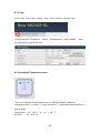
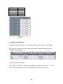
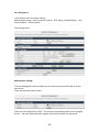
3.2 Software configuration ...........................................................................................................................22
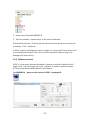
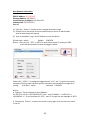
3.2.1 Software installation ........................................................................................................................22
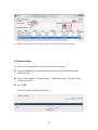
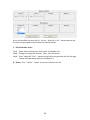
3.2.2 Software overview ..........................................................................................................................23
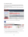
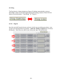
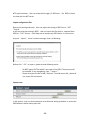
3.2.3 Using IP Service ( & CNT ) ..............................................................................................................26
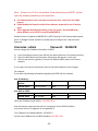
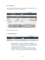
3.3 Internet Setup .........................................................................................................................................27
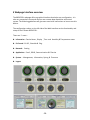
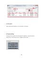
4 WEBPAGE INTERFACE OVERVIEW ........................................................................ 28

- 4 -
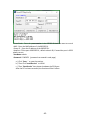
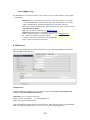
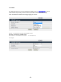
4.1 Information .............................................................................................................................................29
4.1.1 Device Name : ..................................................................................................................................29
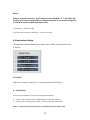
4.1.2 Display..............................................................................................................................................29
4.1.3 Time .................................................................................................................................................30
4.1.4 Humidity & Temperature status ......................................................................................................30
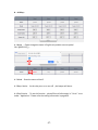
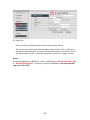
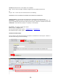
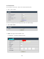
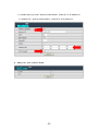
4.2.1 DI-DO ..............................................................................................................................................31
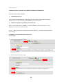
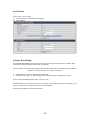
4.2.2 Schedule ..........................................................................................................................................46
4.2.3 Ping ..................................................................................................................................................51
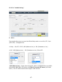
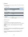
4.3 Network : ................................................................................................................................................56
4.4 Application Settings ................................................................................................................................57
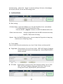
4.4.1 Email ................................................................................................................................................57
4.4.2 DDNS ................................................................................................................................................61
4.4.3 Communication ...............................................................................................................................62
4.4.4 IP Service ..........................................................................................................................................64
4.5 System Setting ........................................................................................................................................65
4.5.1 Management ...................................................................................................................................66
4.5.2 System Information .........................................................................................................................69
4.5.3 System Log ......................................................................................................................................70
4.5.4 Firmware .........................................................................................................................................70
5.CONTROLLING THE DEVICE ................................................................................. 72
CGI HTTP Commands ..................................................................................................................................72
Telnet Control ...............................................................................................................................................74
6.FAQ : ................................................................................................................. 74

- 5 -
1. Introduction
1.1 Overview
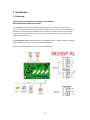
Ethernet-based Data Acquisition and Power Control Module /
Ethernet Peripheral Digit IO controller
The IP9823GP-RL is a cost effective solution for data acquisition, monitoring and control through
network. The module provide IO for data acquisition, Relay for power control module and embedded
webserver for a wide application. IP9823 Series also provides an excellent web server and complete
network and industry standard protocols. It is easily integrated with existing system and play a high
performance network control.
With latching type relay, with RS485 interface to be MODBUS Gateway – 9823 is a stable and powerful
bridge of Modbus /TCP Server on network and the Modbus devices
Please refer the following picture for the overview of IP9823GP-RL

- 6 -

- 7 -
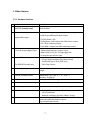
1.2 Main Features
1.2.1 Hardware Features
Item
Description
1
4 Latch Type Relay
16A/250V (memory relay)
Low power dispassion, lower spike, NO heat &
More durable!
2
4 DO
Programable output
COM power voltage is up to 50V, open drain design.
Provide 4 type 400ma pull down output.
* DC(Pull Down / Off)
* Pulse(power cycle) output with 16bit Down counter
* 2K~ 50Hz Frequency output
* Only DO# 1 support ule width modulate) output
3
4 DI
4 General purpose digital input
Provide both type input
1. 500ohm Resistance dry contact input
2. detect (50V~4.5V) /(0~ 3V) logic High/Low
bi-direction wet contact input
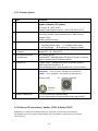
4
2 special DI
*For IP9823GP models only
Provide 3 type input
1. DC logic High/Low detect (Dry/Wet contact)
2. Tachometer (up to 2KHz /120K rpm)
3. 32bit Tally Counter
5
USB Port(option)
For extended HID/CDC and Camera/Storage device/3G
dongle
6
Thermal /Humidity sensor
Temperature: -20 ~ +60 °C / - 4 ~ +136 °F
Humidity: 20-95% RH
7
RS485 bus
receive/send RS485 message to internet
8
PMOD connect (option)
option to I2C/SPI gas, temp/current ADC sensor
9
Antenna (option)
option to wireless LAN ( FCC certificated only)
10
Notification
1. On board Beeper sound notification.
2. LED I/O indication
3. Network notification for Mail / SNMP / Syslog
11
Protection
Isolation Voltage 3,000 VDC . Power Reversal Protection
detect self watch dog timeout reboot.
ping network failure action

- 8 -
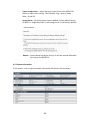
1.2.2 Firmware feature
Item
Description
1
Network
Web server, UPNP , DDNS & Telnet
Modbus to Modbus/TCP gateway
NTP server & SMTP server
Support most Ethernet protocol: DHCP, UDP/TCP/IP, HTTP
2
Security
SSL3.0 , HTTPS, SNMP V2. SMTP ( Gmail , hotmail)
Web server provide 3 levels authentication: Administrator,
Operator, Guest
Base64 password encrypt
3
Event, Alarm Notification
1. SMTP mail notification. 2. Syslog server notify
2. Ping failure event action. 4. Scheduler event action
5. I/O level change & Temperature, Frequency Change
4
SDK and Industrious
Protocol
Provide HTTP CGI command , SNMP V2 & POP3 Mail control .
Modbus/TCP & Bacnet/TCP.
5
IOT/ Device-to-Cloud
Architecture
CNT ( Aviosys server)
Standard MQTT (Message Queue Telemetry Transport ) protocol -
Apply on Amazon, Baidu, Alibaba available
6
Windows AP
IP Power center ( manager and control all Aviosys product ),
IPEdit (local/internet search ) &
Online webpage search www.myipedit.com ( internet search )
7
Mobile APP
* All support APP for Android or iOS system :
- Android APP -- name “IP Power free download in Google Play .
- iOS APP -- name “IPPOWER+ “ free download in Apple AppStore
IPPower+ (iOS) & IPPower (Android)
8
Wireless LAN(Option)
(FCC certificated only, default disable)
AP client mode support (extend wireless LAN range) & WPS
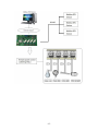
1.2.3 Ethernet I/O control board , Modbus TCP/IP & BacNet TCP/IP
IP9823GP-RL is a module with embedded webserver and based on standard ethernet networking
10/100 Mbps Ethernet and support popular Modbus /TCP or and BacNet /TCP protocols over TCP/IP for
data connection .

- 9 -
1.3 Product Specification
1.3.1 Basic
• Network LAN 10/100Base-T(X)
• Power Input 12 ~ 30 VDC (Reversal Protection)
• Power Consumption : 2W @ 12 VDC ( IP9823LT )
◦ 2.16W @ 12 VDC ( IP9823GP )
• Connectors 1 x RJ-45 (LAN), Plug-in screw terminal block (I/O and power)
• Watchdog Timer System (1.6 second) and Communication (programmable)
• Support Peer-to-Peer
• Support protocol: - Network : HTTP, UDP/TCP, DHCP, SMTP,
- iot/cloud : MQTT, UPNP
- industry : HTTP CGI, SNMP, Modbus/TCP, Bacnet/TCP,
Modbus RTU
• USB 2.0 for extended future HID, CDC, Camera, Storage requirement.
• PING Call Timer System
• Build in RTC timer for schedule
• Option: Wireless LAN extendable
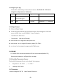
1.3.2 Latching Relay Output
4 pcs Latching type relay and each relay can switch power .
• max. 260 VAC @ 16 A . max. 30 VDC @ 5A
• Relay On Time 15 ms . Relay Off Time 8 ms
• Max. Switching 20 operations/minutes

- 10 -
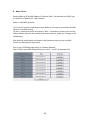
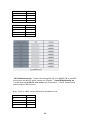
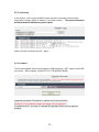
1.3.3 Digital Input (DI)
Provide 6 DI with both dry contact and wet contact. IN ch5 and ch6. of DI can be
assigned to a tally counter or Tachometer.
DI
Logic Level 0
Logic Level 1
Notice
Dry
Below 500 Ohm resistance
close to GND signal.
3 VDC
Wet
Open
5-50 VDC
Connector + / - protection
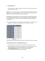
1.3.4 Digital Output
⚫ 4 Channels Digital Output
⚫ Provide 4 of open collector type to pull down output. Sink voltage max. 5~40 VDC
source to GND. (max. current 400mA). Power Dissipation
- Each Channel: 400mA max.
- Total current: 1.5A max.(4 Channels)
⚫ each channel can be assigned a 16bits pulse count
⚫ each channel can be assigned a frequency output (2K ~ 50Hz)
⚫ one channel can be assigned a programmable PWM output
1.3.5 RS-485
1-ch RS-485 ASCII command and Modbus RTU to Ethernet-based(Modbus TCP)
Baud-rate and address is configured from web page
1.3.6 Humidity Temperature Sensor
The Humidity Temperature Sensor on the board. Sensing range
• Temperature: -20 ~ +60 °C / - 4 ~ +136 °F
• Humidity: 20-95 % RH
1.3.7 Protection:
Isolation Voltage 3K VDC . & Power Reversal Protection

- 11 -
1.3.8 Environment:
- Operation: Temperature -10 ~ 70°C (14 ~ 158°F) .
Humidity 20 ~ 95% RH (non-condensing).
- Storage: Temperature -20 ~ 80°C (-4 ~ 176°F) .
Humidity 0 ~ 95% RH (non-condensing)
1.3.9Dimensions:
- 200 x 107x 20 mm ( L/W/ H )
- 203x 122x 50 mm ( L/W/ H ) ( w/ Din Rail Stand)
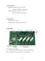
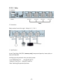
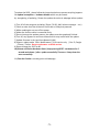
1.4 IO Interface
Upper : 4DI , 2DI , 4DO , RS485 ,
Power line in and power in socket . ( Only select one power input )
Down : Ethernet ( RJ 45) , Reset , Reboot and 4 Latching Relays

- 12 -
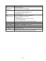
Description
Function
4DI
General purpose
digital input
Provide both type input
1. 500ohm Resistance dry contact input
2. detect (50V~4.5V) /(0~ 3V) logic High/Low bi-direction wet contact input
2 DI
special
Provide 3 type input
1. DC logic High/Low detect (Dry/Wet contact)
2. Tachometer (up to 2KHz /120K rpm)
3. 32bit Tally Counter
4DO
Programable output
COM power voltage is up to 50V, open drain design.
Provide 4 type 400ma pull down output.
* DC(Pull Down / Off)
* Pulse(power cycle) output with 16bit Down counter
* 2K~ 50Hz Frequency output
* Only DO# 1 support PWM ( pule width modulate) output
RS485
Receive/send RS485 message to internet
Power line in
Power input : for line input 12 ~ 30 VDC
Power in socket
Power input : for power adaptor 12V 1A VAC
Network
10/100 Mbps , Ethernet RJ 45connector
RST = Reset
Set back to manufactory default
RAT = Reboot
Reboot the device power
4 Latch Type Relay
16A/250V (memory relay)
Low power dispassion, lower spike, no heat more durable!

- 13 -
2. Hardware installation
2.1 Before Starting
*Before setting up the device make sure of the following:
1.) All the package contents are all included if anything is missing please contact the
dealer where the device was purchased from.
2.) Check the power input cable is working correctly.
3.) Check all cables to make sure there are no problems with it.
2.1.1 Package :
⚫ Standard :
- IP 9823GP-RL .
- CD with manual and software
⚫ Option :
- Power adaptor (12V 1A ) .
- Network cable (RJ45 connector) .
- Din Rail mount
2.1.2 Minimum system Requirements :
- Windows OS with network capacity & web browser .
Like Google Chrome , Safari , IE 9.0 or above .
- Ethernet Hub /Switch ( at least 2 ports)
- Ethernet cable with RJ45 connector
- Power supply for IP9823GP-RL ( 12 ~ 30 VDC unregulated )
2.2 Hardware Connection
This section provides basic information on wiring the power supply, I/O
units, network connection and LED display .

- 14 -
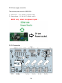
2.2.1 Power supply connection
There are two power source for IP9823GP-RL .
1. Power line in : 12 to 30 VDC ( in Green socket )
2. Power adaptor : 12V 1A VAC ( in Black socket )
MUST only select one power input .
2.2.2 IO connection

- 15 -
The system uses a plug-in screw terminal block for the interface between I/O modules
and field devices. The following information must be considered when connecting
electrical devices to I/O modules.
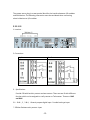
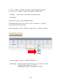
2.2.2.1 DI
1. Location :
2. Connection :
Dry Contact
Wet Contact
3. Specification :
Provide 6 DI with both dry contact and wet contact. There are two DI with different
function which can be assigned to a tally counter or Tachometer. Those are DI#5
and DI#6
3-1 : DI#1 , 2 , 3 & 4 , General purpose digital input. Provide both type input
* 500ohm Resistance dry contact input

- 16 -
* Detect (50V~4.5V) /(0~ 3V) logic High/Low bi-direction wet contact input
3-2 : DI #5 & # 6 , special . Provide 3 type input
* DC logic High/Low detect (Dry/Wet contact)
* Tachometer (up to 2KHz /120K rpm)
* Tally Counter ( 32 bit )
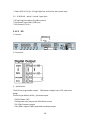
2.2.2.2 DO
1. Location :
2. Connection :
3. Specification :
The 4 DO are programable outputs . COM power voltage is up to 50V, open drain
design.
Provide 4 type 400ma ( MAX. ) pull down output.
* DC(Pull Down / Off)
* Pulse(power cycle) output with 16bit Down counter
* 2K~ 50Hz Frequency output
* Only DO# 1 support PWM ( pule width modulate) output

- 17 -
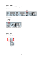
2.2.2.3 Relay
1. Location :
2. Connection :
Relay number from left to right : Relay # 4 , 3 , 2 & 1
3 . Specification :
4 Latch Type Relay: 16A/250V (memory relay) Low power dispassion, lower spike, no
heat more durable!
Latching type relay and each relay can switch power .
* max. 260 VAC @ 16 A . max. 30 VDC @ 5 A
* Relay On Time 15 ms . Relay Off Time 8 ms
*Max. Switching 20 operations/minutes

- 18 -
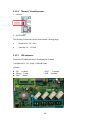
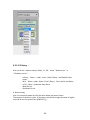
2.2.2.4 RS485
User can receive or send RS485 message to internet .
1. Location :
2. Connection :
3.Specification : Standard RS485 interface .
2.2.2.5 USB
For 4G Dongle application.

- 19 -
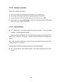
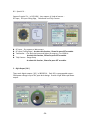
2.2.2.6 Thermal / Humidity sensor
1. Location :
2. Specification :
The Humidity Temperature Sensor on the board. Sensing range
• Temperature: -20 ~ +60 C
• Humidity: 20 ~ 95 RH%
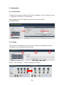
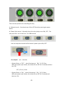
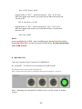
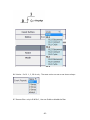
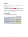
2.2.2.7 LED Indicators
There are LED lights near the IO to indicate the IO status
.
Led lights for DI , DO , Relay , USB and Power
Location :
⚫ 6 DI : in yellow * 4 DO : in orange
⚫ 4 Relay : in blue * USB : in purple
⚫ 1 WF : power

- 20 -
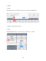
2.2.2.8 Network connection
Please refer following procedure :
1.) Connect the Ethernet cable (RJ45) to the 9823 to user HUB/Switch .
2.) Then connect the power cable into the power input port of the 9823.
3.) Connect the device that user would like to control to the IO of the 9823.
4.) After power in for around 60 seconds , there is a short beep sound for 9823 which
means the system reboot successfully
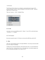
2.2.2.9 Reset & Reboot
⚫ RST : Means Reset , set the device back to manufactory default . Like IP, password,
schedule , ping setting and IO setting .
Keep pressing the RST button for 5 seconds and then release, user will get 4 short
beeps soon as release the RST button , 4 beeps means the device start setting back to
default .
After reset , the device will reboot it selves . So customer will get another short beep
( keep pressing for 5 seconds )
The total time of RESET plus reboot procedure is around 65 seconds
⚫ RAT : Means Reboot , device power reboot .It will take 60 seconds to boot up the
system
Page is loading ...
Page is loading ...
Page is loading ...
Page is loading ...
Page is loading ...
Page is loading ...
Page is loading ...
Page is loading ...
Page is loading ...
Page is loading ...
Page is loading ...
Page is loading ...
Page is loading ...
Page is loading ...
Page is loading ...
Page is loading ...
Page is loading ...
Page is loading ...
Page is loading ...
Page is loading ...
Page is loading ...
Page is loading ...
Page is loading ...
Page is loading ...
Page is loading ...
Page is loading ...
Page is loading ...
Page is loading ...
Page is loading ...
Page is loading ...
Page is loading ...
Page is loading ...
Page is loading ...
Page is loading ...
Page is loading ...
Page is loading ...
Page is loading ...
Page is loading ...
Page is loading ...
Page is loading ...
Page is loading ...
Page is loading ...
Page is loading ...
Page is loading ...
Page is loading ...
Page is loading ...
Page is loading ...
Page is loading ...
Page is loading ...
Page is loading ...
Page is loading ...
Page is loading ...
Page is loading ...
Page is loading ...
Page is loading ...
-
 1
1
-
 2
2
-
 3
3
-
 4
4
-
 5
5
-
 6
6
-
 7
7
-
 8
8
-
 9
9
-
 10
10
-
 11
11
-
 12
12
-
 13
13
-
 14
14
-
 15
15
-
 16
16
-
 17
17
-
 18
18
-
 19
19
-
 20
20
-
 21
21
-
 22
22
-
 23
23
-
 24
24
-
 25
25
-
 26
26
-
 27
27
-
 28
28
-
 29
29
-
 30
30
-
 31
31
-
 32
32
-
 33
33
-
 34
34
-
 35
35
-
 36
36
-
 37
37
-
 38
38
-
 39
39
-
 40
40
-
 41
41
-
 42
42
-
 43
43
-
 44
44
-
 45
45
-
 46
46
-
 47
47
-
 48
48
-
 49
49
-
 50
50
-
 51
51
-
 52
52
-
 53
53
-
 54
54
-
 55
55
-
 56
56
-
 57
57
-
 58
58
-
 59
59
-
 60
60
-
 61
61
-
 62
62
-
 63
63
-
 64
64
-
 65
65
-
 66
66
-
 67
67
-
 68
68
-
 69
69
-
 70
70
-
 71
71
-
 72
72
-
 73
73
-
 74
74
-
 75
75


Ask a question and I''ll find the answer in the document
Finding information in a document is now easier with AI
Related papers
Other documents
-
SCT UVC86 User guide
-
 SOLINTEG DuoCom Owner's manual
-
 Opengear IP POWER User manual
-
Delta Controls O3 Edge User guide
-
Delta Controls O3 Sense User guide
-
Viking RC-4A User manual
-
 Millennium Lighting 9823 Owner's manual
-
XtendLan IPM-401H User manual
-
Honeywell E671781 User manual
-
 SystemAir SAVE VTR 500 L Owner's manual


