Page is loading ...

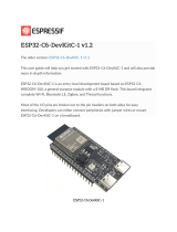
ESP32-S2-MINI-2
User Manual
2.4 GHz Wi-Fi (802.11 b/g/n) module
Built around ESP32-S2 series of SoC (chip revision v1.0), Xtensa®single-core 32-bit LX7 mi-
croprocessor
4 MB flash and optional 2 MB PSRAM in chip package
37 GPIOs, rich set of peripherals
On-board PCB antenna
ESP32-S2-MINI-2
Pre-release v0.5
Espressif Systems
Copyright © 2022
www.espressif.com

1 Module Overview
1 Module Overview
ESP32-S2-MINI-2 is a general-purpose Wi-Fi module. The rich set of peripherals and a small size make this
module an ideal choice for smart homes, industrial automation, health care, consumer electronics, etc.
Table 1: ESP32-S2-MINI-2 Specifications
Categories Parameters Specifications
Wi-Fi Protocols 802.11 b/g/n (up to 150 Mbps)
Frequency range 2412 ~2462 MHz
Hardware
Module interfaces
GPIO, SPI, I2S, UART, I2C, LED PWM, TWAI®, LCD,
Camera interface, ADC, DAC, touch sensor, temper-
ature sensor, USB OTG
Integrated crystal 40 MHz crystal
Operating voltage/Power supply 3.0 V ~3.6 V
Operating current Average: 80 mA
Minimum current delivered by power
supply 500 mA
Ambient temperature –40 °C ~+85 °C/105 °C
Moisture sensitivity level (MSL) Level 3
Espressif Systems 2 ESP32-S2-MINI-2 User Manual v0.5

Contents
Contents
1 Module Overview 2
2 Pin Definitions 4
2.1 Pin Layout 4
2.2 Pin Description 4
3 Get Started 7
3.1 What You Need 7
3.2 Hardware Connection 7
3.3 Set up Development Environment 8
3.3.1 Install Prerequisites 8
3.3.2 Get ESP-IDF 8
3.3.3 Set up Tools 9
3.3.4 Set up Environment Variables 9
3.4 Create Your First Project 9
3.4.1 Start a Project 9
3.4.2 Connect Your Device 9
3.4.3 Configure 10
3.4.4 Build the Project 10
3.4.5 Flash onto the Device 11
3.4.6 Monitor 12
4 U.S. FCC Statement 14
5 Related Documentation and Resources 18
Revision History 19
Espressif Systems 3 ESP32-S2-MINI-2 User Manual v0.5

2 Pin Definitions
2 Pin Definitions
2.1 Pin Layout
The pin diagram below shows the approximate location of pins on the module.
Pin 1
Pin 2
Pin 3
Pin 4
Pin 5
Pin 6
Pin 7
Pin 8
Pin 9
Pin 10
Pin 11
Pin 12
Pin 13
Pin 14
Pin 15
GND
GND
3V3
IO0
IO1
IO2
IO3
IO4
IO5
IO6
IO7
IO8
IO9
IO10
IO11
Pin 63
GND
IO12 Pin 16
Pin 17
Pin 18
Pin 19
Pin 20
Pin 21
Pin 22
Pin 23
Pin 24
Pin 25
Pin 26
Pin 27
Pin 28
Pin 29
Pin 30
Pin 64
GND
Pin 31
IO13
IO14
IO15
IO16
IO17
IO18
IO19
IO20
IO21
IO26
NC
IO33
IO34
GND
Pin 32
Pin 33
Pin 34
Pin 35
Pin 36
Pin 37
Pin 38
Pin 39
Pin 40
Pin 41
Pin 42
Pin 43
Pin 44
Pin 45
Pin 65
GND
Pin 62
GND
Pin 46
Pin 47
Pin 48
Pin 49
Pin 50
Pin 51
Pin 52
Pin 53
Pin 54
Pin 55
Pin 56
Pin 57
Pin 58
Pin 59
Pin 60
Pin 61
GND
GND GND GND
GNDGND
GND GND GND
IO35
IO36
IO37
IO38
IO39
IO40
IO41
IO42
TXD0
RXD0
IO45
GND
GND
IO46
EN
GND
GND
GND
GND
GND
GND
GND
GND
GND
GND
GND
GND
GND
GND
GND
Keepout Zone
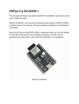
Figure 1: Pin Layout (Top View)
2.2 Pin Description
The module has 65 pins. See pin definitions in Table 2.
For peripheral pin configurations, please refer to ESP32-S2 Series Datasheet.
Table 2: Pin Definitions
Name No. Type1Function
GND
1, 2, 30,
42, 43,
46-65
P Ground
3V3 3 P Power supply
Cont’d on next page
Espressif Systems 4 ESP32-S2-MINI-2 User Manual v0.5

2 Pin Definitions
Table 2 – cont’d from previous page
Name No. Type1Function
IO0 4 I/O/T RTC_GPIO0, GPIO0
IO1 5 I/O/T RTC_GPIO1, GPIO1, TOUCH1, ADC1_CH0
IO2 6 I/O/T RTC_GPIO2, GPIO2, TOUCH2, ADC1_CH1
IO3 7 I/O/T RTC_GPIO3, GPIO3, TOUCH3, ADC1_CH2
IO4 8 I/O/T RTC_GPIO4, GPIO4, TOUCH4, ADC1_CH3
IO5 9 I/O/T RTC_GPIO5, GPIO5, TOUCH5, ADC1_CH4
IO6 10 I/O/T RTC_GPIO6, GPIO6, TOUCH6, ADC1_CH5
IO7 11 I/O/T RTC_GPIO7, GPIO7, TOUCH7, ADC1_CH6
IO8 12 I/O/T RTC_GPIO8, GPIO8, TOUCH8, ADC1_CH7
IO9 13 I/O/T RTC_GPIO9, GPIO9, TOUCH9, ADC1_CH8, FSPIHD
IO10 14 I/O/T RTC_GPIO10, GPIO10, TOUCH10, ADC1_CH9, FSPICS0, FSPIIO4
IO11 15 I/O/T RTC_GPIO11, GPIO11, TOUCH11, ADC2_CH0, FSPID, FSPIIO5
IO12 16 I/O/T RTC_GPIO12, GPIO12, TOUCH12, ADC2_CH1, FSPICLK, FSPIIO6
IO13 17 I/O/T RTC_GPIO13, GPIO13, TOUCH13, ADC2_CH2, FSPIQ, FSPIIO7
IO14 18 I/O/T RTC_GPIO14, GPIO14, TOUCH14, ADC2_CH3, FSPIWP, FSPIDQS
IO15 19 I/O/T RTC_GPIO15, GPIO15, U0RTS, ADC2_CH4, XTAL_32K_P
IO16 20 I/O/T RTC_GPIO16, GPIO16, U0CTS, ADC2_CH5, XTAL_32K_N
IO17 21 I/O/T RTC_GPIO17, GPIO17, U1TXD, ADC2_CH6, DAC_1
IO18 22 I/O/T RTC_GPIO18, GPIO18, U1RXD, ADC2_CH7, DAC_2, CLK_OUT3
IO19 23 I/O/T RTC_GPIO19, GPIO19, U1RTS, ADC2_CH8, CLK_OUT2, USB_D-
IO20 24 I/O/T RTC_GPIO20, GPIO20, U1CTS, ADC2_CH9, CLK_OUT1, USB_D+
IO21 25 I/O/T RTC_GPIO21, GPIO21
IO26 226 I/O/T SPICS1, GPIO26
NC 27 — NC
IO33 28 I/O/T SPIIO4, GPIO33, FSPIHD
IO34 29 I/O/T SPIIO5, GPIO34, FSPICS0
IO35 31 I/O/T SPIIO6, GPIO35, FSPID
IO36 32 I/O/T SPIIO7, GPIO36, FSPICLK
IO37 33 I/O/T SPIDQS, GPIO37, FSPIQ
IO38 34 I/O/T GPIO38, FSPIWP
IO39 35 I/O/T MTCK, GPIO39, CLK_OUT3
IO40 36 I/O/T MTDO, GPIO40, CLK_OUT2
IO41 37 I/O/T MTDI, GPIO41, CLK_OUT1
IO42 38 I/O/T MTMS, GPIO42
TXD0 39 I/O/T U0TXD, GPIO43, CLK_OUT1
RXD0 40 I/O/T U0RXD, GPIO44, CLK_OUT2
IO45 41 I/O/T GPIO45
IO46 44 I GPIO46
EN 45 I
High: on, enables the chip.
Low: off, the chip powers off.
Note: Do not leave the EN pin floating.
Espressif Systems 5 ESP32-S2-MINI-2 User Manual v0.5

2 Pin Definitions
1P: power supply; I: input; O: output; T: high impedance.
2IO26 is used by the embedded PSRAM on the ESP32-S2-MINI-2-N4R2 module, and cannot be used
for other purposes.
Espressif Systems 6 ESP32-S2-MINI-2 User Manual v0.5

3 Get Started
3 Get Started
3.1 What You Need
To develop applications for module you need:
• 1 x ESP32-S2-MINI-2
• 1 x Espressif RF testing board
• 1 x USB-to-Serial board
• 1 x Micro-USB cable
• 1 x PC running Linux
In this user guide, we take Linux operating system as an example. For more information about the configuration
on Windows and macOS, please refer to ESP-IDF Programming Guide.
3.2 Hardware Connection
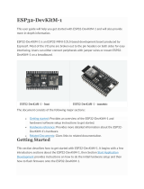
1. Solder the ESP32-S2-MINI-2 module to the RF testing board as shown in Figure 2.
Figure 2: Hardware Connection
2. Connect the RF testing board to the USB-to-Serial board via TXD, RXD, and GND.
3. Connect the USB-to-Serial board to the PC.
4. Connect the RF testing board to the PC or a power adapter to enable 5 V power supply, via the Micro-USB
cable.
5. During download, connect IO0 to GND via a jumper. Then, turn ”ON” the testing board.
6. Download firmware into flash. For details, see the sections below.
Espressif Systems 7 ESP32-S2-MINI-2 User Manual v0.5

3 Get Started
7. After download, remove the jumper on IO0 and GND.
8. Power up the RF testing board again. The module will switch to working mode. The chip will read
programs from flash upon initialization.
Note:
IO0 is internally logic high. If IO0 is set to pull-up, the Boot mode is selected. If this pin is pull-down or left floating, the
Download mode is selected. For more information on ESP32-S2-MINI-2, please refer to ESP32-S2 Series Datasheet.
3.3 Set up Development Environment
The Espressif IoT Development Framework (ESP-IDF for short) is a framework for developing applications based
on the Espressif SoCs. Users can develop applications with ESP32-S2 in Windows/Linux/macOS based on
ESP-IDF. Here we take Linux operating system as an example.
3.3.1 Install Prerequisites
To compile with ESP-IDF you need to get the following packages:
• CentOS 7 & 8:
1sudo yum -y update && sudo yum install git wget flex bison gperf python3 python3-
pip
2python3-setuptools cmake ninja-build ccache dfu-util libusbx
• Ubuntu and Debian:
1sudo apt-get install git wget flex bison gperf python3 python3-pip python3-
setuptools
2cmake ninja-build ccache libffi-dev libssl-dev dfu-util libusb-1.0-0
• Arch:
1sudo pacman -S --needed gcc git make flex bison gperf python-pip cmake ninja
ccache
2dfu-util libusb
Note:
• This guide uses the directory ~/esp on Linux as an installation folder for ESP-IDF.
• Keep in mind that ESP-IDF does not support spaces in paths.
3.3.2 Get ESP-IDF
To build applications for ESP32-S2-MINI-2 module, you need the software libraries provided by Espressif in
ESP-IDF repository.
To get ESP-IDF, create an installation directory (~/esp) to download ESP-IDF to and clone the repository with ‘git
clone’:
Espressif Systems 8 ESP32-S2-MINI-2 User Manual v0.5

3 Get Started
1mkdir -p ~/esp
2cd ~/esp
3git clone --recursive https://github.com/espressif/esp-idf.git
ESP-IDF will be downloaded into ~/esp/esp-idf. Consult ESP-IDF Versions for information about which ESP-IDF
version to use in a given situation.
3.3.3 Set up Tools
Aside from the ESP-IDF, you also need to install the tools used by ESP-IDF, such as the compiler, debugger,
Python packages, etc. ESP-IDF provides a script named ’install.sh’ to help set up the tools in one go.
1cd ~/esp/esp-idf
2./install.sh
3.3.4 Set up Environment Variables
The installed tools are not yet added to the PATH environment variable. To make the tools usable from the
command line, some environment variables must be set. ESP-IDF provides another script ’export.sh’ which does
that. In the terminal where you are going to use ESP-IDF, run:
1. $HOME/esp/esp-idf/export.sh
Now everything is ready, you can build your first project on ESP32-S2-MINI-2 module.
3.4 Create Your First Project
3.4.1 Start a Project
Now you are ready to prepare your application for ESP32-S2-MINI-2 module. You can start with
get-started/hello_world project from examples directory in ESP-IDF.
Copy get-started/hello_world to ~/esp directory:
1cd ~/esp
2cp -r $IDF_PATH/examples/get-started/hello_world .
There is a range of example projects in the examples directory in ESP-IDF. You can copy any project in the same
way as presented above and run it. It is also possible to build examples in-place, without copying them
first.
3.4.2 Connect Your Device
Now connect your module to the computer and check under what serial port the module is visible. Serial ports in
Linux start with ‘/dev/tty’ in their names. Run the command below two times, first with the board unplugged,
then with plugged in. The port which appears the second time is the one you need:
1ls /dev/tty*
Note:
Keep the port name handy as you will need it in the next steps.
Espressif Systems 9 ESP32-S2-MINI-2 User Manual v0.5

3 Get Started
3.4.3 Configure
Navigate to your ‘hello_world’ directory from Step 3.4.1. Start a Project, set ESP32-S2 chip as the target and run
the project configuration utility ‘menuconfig’.
1cd ~/esp/hello_world
2idf.py set-target esp32s2
3idf.py menuconfig
Setting the target with ‘idf.py set-target ESP32-S2’ should be done once, after opening a new project. If the
project contains some existing builds and configuration, they will be cleared and initialized. The target may be
saved in environment variable to skip this step at all. See Selecting the Target for additional information.
If the previous steps have been done correctly, the following menu appears:
Figure 3: Project Configuration - Home Window
You are using this menu to set up project specific variables, e.g. Wi-Fi network name and password, the
processor speed, etc. Setting up the project with menuconfig may be skipped for “hello_word”. This example will
run with default configuration
The colors of the menu could be different in your terminal. You can change the appearance with the option
‘-�-style’�. Please run ‘idf.py menuconfig -�-help’�for further information.
3.4.4 Build the Project
Build the project by running:
1idf.py build
This command will compile the application and all ESP-IDF components, then it will generate the bootloader,
partition table, and application binaries.
1$ idf.py build
2Running cmake in directory /path/to/hello_world/build
3Executing ”cmake -G Ninja --warn-uninitialized /path/to/hello_world”...
Espressif Systems 10 ESP32-S2-MINI-2 User Manual v0.5

3 Get Started
4Warn about uninitialized values.
5-- Found Git: /usr/bin/git (found version ”2.17.0”)
6-- Building empty aws_iot component due to configuration
7-- Component names: ...
8-- Component paths: ...
9
10 ... (more lines of build system output)
11
12 [527/527] Generating hello_world.bin
13 esptool.py v2.3.1
14
15 Project build complete. To flash, run this command:
16 ../../../components/esptool_py/esptool/esptool.py -p (PORT) -b 921600
17 write_flash --flash_mode dio --flash_size detect --flash_freq 40m
18 0x10000 build/hello_world.bin build 0x1000 build/bootloader/bootloader.bin 0x8000
19 build/partition_table/partition-table.bin
20 or run ’idf.py -p PORT flash’
If there are no errors, the build will finish by generating the firmware binary .bin file.
3.4.5 Flash onto the Device
Flash the binaries that you just built onto your module by running:
1idf.py -p PORT [-b BAUD] flash
Replace PORT with your ESP32-S2 board’s serial port name from Step: Connect Your Device.
You can also change the flasher baud rate by replacing BAUD with the baud rate you need. The default baud
rate is 460800.
For more information on idf.py arguments, see idf.py.
Note:
The option ‘flash‘ automatically builds and flashes the project, so running ‘idf.py build‘ is not necessary.
When flashing, you will see the output log similar to the following:
1...
2esptool.py esp32s2 -p /dev/ttyUSB0 -b 460800 --before=default_reset --after=hard_reset
3write_flash --flash_mode dio --flash_freq 80m --flash_size 4 MB 0x0 bootloader/bootloader.
bin
40x10000 hello_world.bin 0x8000 partition_table/partition-table.bin
5esptool.py v3.2-dev
6Serial port /dev/ttyUSB0
7Connecting....
8Chip is ESP32-S2
9Features: WiFi
10 Crystal is 40MHz
11 MAC: 7c:df:a1:e0:00:64
12 Uploading stub...
13 Running stub...
Espressif Systems 11 ESP32-S2-MINI-2 User Manual v0.5

3 Get Started
14 Stub running...
15 Changing baud rate to 460800
16 Changed.
17 Configuring flash size...
18 Flash will be erased from 0x00000000 to 0x00004fff...
19 Flash will be erased from 0x00010000 to 0x00039fff...
20 Flash will be erased from 0x00008000 to 0x00008fff...
21 Compressed 18896 bytes to 11758...
22 Writing at 0x00000000... (100 %)
23 Wrote 18896 bytes (11758 compressed) at 0x00000000 in 0.5 seconds (effective 279.9 kbit/s)
...
24 Hash of data verified.
25 Compressed 168208 bytes to 88178...
26 Writing at 0x00010000... (16 %)
27 Writing at 0x0001a80f... (33 %)
28 Writing at 0x000201f1... (50 %)
29 Writing at 0x00025dcf... (66 %)
30 Writing at 0x0002d0be... (83 %)
31 Writing at 0x00036c07... (100 %)
32 Wrote 168208 bytes (88178 compressed) at 0x00010000 in 2.4 seconds (effective 569.2 kbit/s
)...
33 Hash of data verified.
34 Compressed 3072 bytes to 103...
35 Writing at 0x00008000... (100 %)
36 Wrote 3072 bytes (103 compressed) at 0x00008000 in 0.1 seconds (effective 478.9 kbit/s)...
37 Hash of data verified.
38
39 Leaving...
40 Hard resetting via RTS pin...
41 Done
If there are no issues by the end of the flash process, the board will reboot and start up the “hello_world”
application.
3.4.6 Monitor
To check if “hello_world” is indeed running, type ‘idf.py -p PORT monitor‘ (Do not forget to replace PORT with
your serial port name).
This command launches the IDF Monitor application:
1$ idf.py -p /dev/ttyUSB0 monitor
2Running idf_monitor in directory [...]/esp/hello_world/build
3Executing ”python [...]/esp-idf/tools/idf_monitor.py -b 115200
4[...]/esp/hello_world/build/hello-world.elf”...
5--- idf_monitor on /dev/ttyUSB0 115200 ---
6--- Quit: Ctrl+] | Menu: Ctrl+T | Help: Ctrl+T followed by Ctrl+H ---
7ets Jun 8 2016 00:22:57
8
9rst:0x1 (POWERON_RESET),boot:0x13 (SPI_FAST_FLASH_BOOT)
10 ets Jun 8 2016 00:22:57
Espressif Systems 12 ESP32-S2-MINI-2 User Manual v0.5

3 Get Started
11 ...
After startup and diagnostic logs scroll up, you should see “Hello world!” printed out by the application.
1...
2Hello world!
3Restarting in 10 seconds...
4This is esp32s2 chip with 1 CPU core, WiFi,
5silicon revision 1
6Minimum free heap size: 390684 bytes
7Restarting in 9 seconds...
8Restarting in 8 seconds...
9Restarting in 7 seconds...
To exit IDF monitor use the shortcut Ctrl+].
That’s all what you need to get started with ESP32-S2-MINI-2 module! Now you are ready to try some other
examples in ESP-IDF, or go right to developing your own applications.
Espressif Systems 13 ESP32-S2-MINI-2 User Manual v0.5

4 U.S. FCC Statement
4 U.S. FCC Statement
The device complies with KDB 996369 D03 OEM Manual v01. Below are integration instructions for host product
manufacturers according to the KDB 996369 D03 OEM Manual v01.
List of Applicable FCC Rules
FCC Part 15 Subpart C 15.247
Specific Operational Use Conditions
The module has WiFi functions.
• Operation Frequency:
–WiFi: 2412 ~2462 MHz
• Number of Channel:
–WiFi: 11
• Modulation:
–WiFi: DSSS; OFDM
• Type: On-board PCB antenna
• Gain: 4.54 dBi Max
The module can be used for IoT applications with a maximum 4.54 dBi antenna. The host manufacturer installing
this module into their product must ensure that the final composit product complies with the FCC requirements
by a technical assessment or evaluation to the FCC rules, including the transmitter operation. The host
manufacturer has to be aware not to provide information to the end user regarding how to install or remove this
RF module in the user’s manual of the end product which integrates this module. The end user manual shall
include all required regulatory information/warning as show in this manual.
Limited Module Procedures
Not applicable. The module is a single module and complies with the requirement of FCC Part 15.212.
Trace Antenna Designs
Not applicable. The module has its own antenna, and does not need a host’s printed board microstrip trace
antenna, etc.
RF Exposure Considerations
The module must be installed in the host equipment such that at least 20cm is maintained between the antenna
and users’ body; and if RF exposure statement or module layout is changed, then the host product manufacturer
required to take responsibility of the module through a change in FCC ID or new application. The FCC ID of the
module cannot be used on the final product. In these circumstances, the host manufacturer will be responsible
for re-evaluating the end product (including the transmitter) and obtaining a separate FCC authorization.
Espressif Systems 14 ESP32-S2-MINI-2 User Manual v0.5

4 U.S. FCC Statement
Antennas
Antenna specification are as follows:
• Type: On-board PCB antenna
• Gain: 4.54 dBi
This device is intended only for host manufacturers under the following conditions:
• The transmitter module may not be co-located with any other transmitter or antenna.
• The module shall be only used with the external antenna(s) that has been originally tested and certified with
this module.
• The antenna must be either permanently attached or employ a ‘unique’ antenna coupler.
As long as the conditions above are met, further transmitter test will not be required. However, the host
manufacturer is still responsible for testing their end-product for any additional compliance requirements required
with this module installed (for example, digital device emissions, PC peripheral requirements, etc.).
Label and Compliance Information
Host product manufacturers need to provide a physical or e-label stating “Contains FCC ID:
2AC7Z-ESPS2MINI2” with their finished product.
Information on test modes and additional testing requirements
• Operation Frequency:
–WiFi: 2412 ~2462 MHz
• Number of Channel:
–WiFi: 11
• Modulation:
–WiFi: DSSS; OFDM
Host manufacturer must perform test of radiated and conducted emission and spurious emission, etc., according
to the actual test modes for a stand-alone modular transmitter in a host, as well as for multiple simultaneously
transmitting modules or other transmitters in a host product. Only when all the test results of test modes comply
with FCC requirements, then the end product can be sold legally.
Additional testing, Part 15 Subpart B compliant
The modular transmitter is only FCC authorized for FCC Part 15 Subpart C 15.247 and that the host product
manufacturer is responsible for compliance to any other FCC rules that apply to the host not covered by the
modular transmitter grant of certification. If the grantee markets their product as being Part 15 Subpart B
compliant (when it also contains unintentional-radiator digital circuity), then the grantee shall provide a notice
stating that the final host product still requires Part 15 Subpart B compliance testing with the modular transmitter
installed.
This equipment has been tested and found to comply with the limits for a Class B digital device, pursuant to
Part15 of the FCC Rules. These limits are designed to provide reasonable protection against harmful interference
Espressif Systems 15 ESP32-S2-MINI-2 User Manual v0.5

4 U.S. FCC Statement
in a residential installation. This equipment generates, uses and can radiate radio frequency energy and, if not
installed and used in accordance with the instructions, may cause harmful interference to radio
communications.
However, there is no guarantee that interference will not occur in a particular installation. If this equipment does
cause harmful interference to radio or television reception, which can be determined by turning the equipment off
and on, the user is encouraged to try to correct the interference by one of the following measures:
• Reorient or relocate the receiving antenna.
• Increase the separation between the equipment and receiver.
• Connect the equipment into an outlet on a circuit different from that to which the receiver is connected.
• Consult the dealer or an experienced radio/TV technician for help.
This device complies with Part 15 of the FCC Rules. Operation is subject to the following two conditions:
• This device may not cause harmful interference.
• This device must accept any interference received, including interference that may cause undesired
operation.
Caution:
Any changes or modifications not expressly approved by the party responsible for compliance could void the user’s
authority to operate the equipment.
This equipment complies with FCC RF radiation exposure limits set forth for an uncontrolled environment. This
device and its antenna must not be co-located or operating in conjunction with any other antenna or transmitter.
The antennas used for this transmitter must be installed to provide a separation distance of at least 20 cm from
all persons and must not be co-located or operating in conjunction with any other antenna or transmitter.
OEM Integration Instructions
This device is intended only for OEM integrators under the following conditions:
• The transmitter module may not be co-located with any other transmitter or antenna.
• The module shall be only used with the external antenna(s) that has been originally tested and certified with
this module.
As long as the conditions above are met, further transmitter test will not be required. However, the OEM
integrator is still responsible for testing their end-product for any additional compliance requirements required
with this module installed (for example, digital device emissions, PC peripheral requirements, etc.).
Validity of Using the Module Certification
In the event that these conditions cannot be met (for example certain laptop configurations or co-location with
another transmitter), then the FCC authorization for this module in combination with the host equipment is no
longer considered valid and the FCC ID of the module cannot be used on the final product. In these
circumstances, the OEM integrator will be responsible for re-evaluating the end product (including the transmitter)
and obtaining a separate FCC authorization.
Espressif Systems 16 ESP32-S2-MINI-2 User Manual v0.5

4 U.S. FCC Statement
End Product Labeling
The final end product must be labeled in a visible area with the following: “Contains Transmitter Module FCC ID:
2AC7Z-ESPS2MINI2”.
Espressif Systems 17 ESP32-S2-MINI-2 User Manual v0.5

5 Related Documentation and Resources
5 Related Documentation and Resources
Related Documentation
•ESP32-S2 Series Datasheet –Specifications of the ESP32-S2 hardware.
•ESP32-S2 Technical Reference Manual –Detailed information on how to use the ESP32-S2 memory and peripherals.
•ESP32-S2 Hardware Design Guidelines –Guidelines on how to integrate the ESP32-S2 into your hardware product.
•ESP32-S2 Series SoC Errata –Descriptions of errors in ESP32-S2 series of SoCs from chip revision 0 forward.
•Certicates
https://espressif.com/en/support/documents/certificates
•ESP32-S2 Product/Process Change Notications (PCN)
https://espressif.com/en/support/documents/pcns
•ESP32-S2 Advisories –Information on security, bugs, compatibility, component reliability.
https://espressif.com/en/support/documents/advisories
•Documentation Updates and Update Notication Subscription
https://espressif.com/en/support/download/documents
Developer Zone
•ESP-IDF Programming Guide for ESP32-S2 –Extensive documentation for the ESP-IDF development framework.
•ESP-IDF and other development frameworks on GitHub.
https://github.com/espressif
•ESP32 BBS Forum –Engineer-to-Engineer (E2E) Community for Espressif products where you can post questions,
share knowledge, explore ideas, and help solve problems with fellow engineers.
https://esp32.com/
•The ESP Journal –Best Practices, Articles, and Notes from Espressif folks.
https://blog.espressif.com/
• See the tabs SDKs and Demos,Apps,Tools,AT Firmware.
https://espressif.com/en/support/download/sdks-demos
Products
•ESP32-S2 Series SoCs –Browse through all ESP32-S2 SoCs.
https://espressif.com/en/products/socs?id=ESP32-S2
•ESP32-S2 Series Modules –Browse through all ESP32-S2-based modules.
https://espressif.com/en/products/modules?id=ESP32-S2
•ESP32-S2 Series DevKits –Browse through all ESP32-S2-based devkits.
https://espressif.com/en/products/devkits?id=ESP32-S2
•ESP Product Selector –Find an Espressif hardware product suitable for your needs by comparing or applying filters.
https://products.espressif.com/#/product-selector?language=en
Contact Us
• See the tabs Sales Questions,Technical Enquiries,Circuit Schematic & PCB Design Review,Get Samples
(Online stores), Become Our Supplier,Comments & Suggestions.
https://espressif.com/en/contact-us/sales-questions
Espressif Systems 18 ESP32-S2-MINI-2 User Manual v0.5

Revision History
Revision History
Date Version Release notes
2022-09-22 v0.5 Preliminary release
Espressif Systems 19 ESP32-S2-MINI-2 User Manual v0.5

www.espressif.com
Disclaimer and Copyright Notice
Information in this document, including URL references, is subject to change without notice.
ALL THIRD PARTY’S INFORMATION IN THIS DOCUMENT IS PROVIDED AS IS WITH NO
WARRANTIES TO ITS AUTHENTICITY AND ACCURACY.
NO WARRANTY IS PROVIDED TO THIS DOCUMENT FOR ITS MERCHANTABILITY, NON-
INFRINGEMENT, FITNESS FOR ANY PARTICULAR PURPOSE, NOR DOES ANY WARRANTY
OTHERWISE ARISING OUT OF ANY PROPOSAL, SPECIFICATION OR SAMPLE.
All liability, including liability for infringement of any proprietary rights, relating to use of information
in this document is disclaimed. No licenses express or implied, by estoppel or otherwise, to any
intellectual property rights are granted herein.
The Wi-Fi Alliance Member logo is a trademark of the Wi-Fi Alliance. The Bluetooth logo is a
registered trademark of Bluetooth SIG.
All trade names, trademarks and registered trademarks mentioned in this document are property
of their respective owners, and are hereby acknowledged.
Copyright © 2022 Espressif Systems (Shanghai) Co., Ltd. All rights reserved.
/