Page is loading ...

OIL-FIRED WATER AND STEAM KNOCKED DOWN BOILERS
AND BOILER/BURNER UNITS/NO. 2 OIL
See publication LD-41K for assembly and parts and publication LD-42KB for approved oil burners.
INSTALLATION AND OPERATING INSTRUCTIONS
KEEP BOILER AREA CLEAR AND FREE FROM
COMBUSTIBLE MATERIALS, GASOLINE AND
OTHER FLAMMABLE VAPORS AND LIQUIDS.
FAILURE TO ADHERE TO ABOVE SAFETY WARN-
ING, MAY RESULT IN PERSONAL INJURY OR
DEATH AND PROPERTY DAMAGE.
SAFETY WARNING:
CONTENTS . . . . . . . . . . . . . . . . . . . . . . . . . . . . . .PAGE
Assembly . . . . . . . . . . . . . . . . . . . . . . .see pub. #LD-41K
Ratings and Dimensions . . . . . . . . . . . . . . . . . . . . . . . .2
Installation Requirements:
Boiler Location . . . . . . . . . . . . . . . . . . . . . . . . . . . . .3
Clearances . . . . . . . . . . . . . . . . . . . . . . . . . . . . . . . .3
Chimney Requirements . . . . . . . . . . . . . . . . . . . . . . .3
Air Supply and Venting . . . . . . . . . . . . . . . . . . . . . . .3
Controls and Accessories . . . . . . . . . . . . . . . . . . . . .4
Piping for Steam Boilers . . . . . . . . . . . . . . . . . . . . . .4
Blowing Off a Steam Boiler . . . . . . . . . . . . . . . . . . . .4
Cleaning Piping System . . . . . . . . . . . . . . . . . . . . . .5
Piping for Water Units . . . . . . . . . . . . . . . . . . . . . . . .5
Piping for Tankless Heater . . . . . . . . . . . . . . . . . . . .5
Installing Burner . . . . . . . . . . . . . . . . . . . . . . . . . . . .6
Oil Supply Piping . . . . . . . . . . . . . . . . . . . . . . . . . . . .6
Wiring the Boiler . . . . . . . . . . . . . . . . . . . . . . . . . . . .6
Vent Piping and Draft Regulator . . . . . . . . . . . . . . . .6
Operating Instructions:
Precautions Before Starting . . . . . . . . . . . . . . . . . . .6
Start up . . . . . . . . . . . . . . . . . . . . . . . . . . . . . . . . . . .6
Cleaning and Filling New
Water Boiler . . . . . . . . . . . . . . . . . . . . . . . . . . . .6
Steam Boiler . . . . . . . . . . . . . . . . . . . . . . . . . . . .7
Low Water Cut-off check-out . . . . . . . . . . . . . . . . . . .8
Pressure Control check-out . . . . . . . . . . . . . . . . . . . .8
Replacement of Steam Boiler . . . . . . . . . . . . . . . . . .8
Wiring Diagrams . . . . . . . . . . . . . . . . . . . . . . . . . . . .9-12
Burner Data . . . . . . . . . . . . . . . . . . .see pub. # LD-42KB
Care and Maintenance:
Extended Shutdown . . . . . . . . . . . . . . . . . . . . . . . .13
Freezing Protection . . . . . . . . . . . . . . . . . . . . . . . . .13
Oil Burner . . . . . . . . . . . . . . . . . . . . . . . . . . . . . . . .13
General Maintenance . . . . . . . . . . . . . . . . . . . . . . .13
THIS MANUAL MUST BE LEFT WITH OWNER
AND SHOULD BE HUNG ON OR ADJACENT TO
THE BOILER FOR REFERENCE.
In addition, where required by the authority having ju-
risdiction, the installation must conform to American
Society of Mechanical Engineers Safety Code for
Controls and Safety Devices for Automatically Fired
Boilers, No. CSD-1, latest edition.
IMPORTANT: This boiler must be installed by a
trained, experienced, service technician, licensed for
the installation and servicing of oil burning equipment or
otherwise qualified by the authorities having jurisdiction
over the installation.
IMPORTANT: The installation of this equipment must
conform to the requirements of the authority having ju-
risdiction or, in the absence of such requirements, to
the installation of Oil Burning Equipment, ANSI/NFPA
31, latest edition, and to the National Electrical Code
ANSI-NFPA 70, latest edition. The installation must
also conform to the additional requirements in this
Slant/Fin Instruction Manual. Where there is any dif-
ference, the more stringent requirement shall govern.
Printed in U.S.A. 0402 Publication No. LD-43K
Part No. 43-0268
LIBERTY II
®

2 LIBERTY
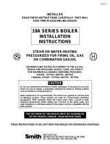
TAPPINGS AND OPENINGS
Tapping Loc. Steam Boiler
13” supply
1A* 2” supply onn rear section *
33/4” steam safety valve
41/4” siphon, pressure gauge & pressure cut-out
83/4” alternate electronic low water cut-off
91-1/2” skimmer tapping
10 1/2” low limit for tankless
11A 1/2” tankless inlet
11B 1/2” tankless outlet
12 1/2” steam gauge glass & 67 LWCO
13 1-1/2” bushed to 3/4” for drain cock
14 1-1/2” condensate return
Tapping Loc. Water Boiler
1 1-1/2” supply
2 3/4” air vent or expansion tank
3 3/4” water relief valve
5A 1/2” tankless inlet
5B 1/2” tankless outlet
6 1/4” pressure temp. gauge
7 1/2” high limit, hi/lo or combination control
13 1-1/2” return & 3/4” drain cock
14 1-1/2” alternate return Figure 1
DIMENSIONS
Figure 2
RATINGS
Boiler
Model
No.*
I=B=R Burner
Capacity
Oil Input
GPH† BTUH
D.O.E.
Heating
Capacity
MBH
Water Steam
I=B=R
Net Ratings
Water
MBH *
Steam
MBH *
Steam
Sq. Ft.
I=B=R Chimney Size
Nom. Rect.
x Height §
(in x in x ft)
I.D. Round
x Height
(in x ft)
A.F.U.E.
%
Water Steam
Dimensions (inches)
Boiler
Length
“A”
Front to
Flue ¢
“B”
Flue
Dia.
“C”
Return
Circulator
Flange
‘D”
Overall
Length
“E”
Boiler
Sect.
Tankless
Heater
GPM * *
Water Steam
LD-20 0.75 105,000 90 79 8 x 8 x 15 5 x 15 83.50 111⁄289⁄326❏11⁄4241⁄42 2.20
LD-20 BK 0.95 133,000 110 96 8 x 8 x 15 5 x 15 81.76 111⁄289⁄32 6❏11⁄4241⁄42 2.40
LD-30H 1.00 140,000 121 105 8 x 8 x 15 6 x 15 86.00 147⁄8101⁄3261
1⁄4275⁄83 3.10
1.10 154,000 134 134 117 101 421 8 x 8 x 15 6 x 15 84.85 84.15 147⁄8101⁄32 61
1⁄4275⁄83 3.20 3.00
1.25 175,000 151 131 8 x 8 x 15 6 x 15 83.50 147⁄8101⁄32 61
1⁄4275⁄83 3.40
LD-40H 1.50 210,000 182 179 158 134 558 8 x 8 x 15 7 x 15 86.00 84.00 181⁄41123⁄32 71
1⁄431 4 3.80 3.40
1.60 224,000 195 195 170 146 608 8 x 8 x 15 7 x 15 84.45 83.80 181⁄41123⁄32 71
1⁄431 4 3.90 3.50
1.80 252,000 218 190 8 x 8 x 15 7 x 15 83.33 181⁄41123⁄32 71
1⁄431 4 4.15
LD-50H 2.00 280,000 243 239 211 179 746 8 x 8 x 15 8 x 15 86.00 84.00 215⁄81313⁄32 81
1⁄2343⁄85 4.30 3.90
2.10 294,000 256 255 223 191 796 8 x 8 x 15 8 x 15 84.06 83.45 215⁄81313⁄32 81
1⁄2343⁄85 4.40 4.00
2.35 329,000 272§ 237 8 x 12 x 15 8 x 15 215⁄81313⁄32 81
1⁄2343⁄85 4.70
2.60 364,000 298§ 298§ 259 224 933 8 x 12 x 15 10 x 15 25 153⁄32 81
1⁄2373⁄46 4.90 4.50
2.85 399,000 327§ 284 8 x 12 x 15 10 x 15 25 153⁄32 81
1⁄2373⁄46 5.20
3.10 434,000 352§ 354§ 306 266 1108 8 x 12 x 15 10 x 15 283⁄81625⁄32 9 411⁄87 5.45 5.00
3.35 469,000 381§ 331 8 x 12 x 15 10 x 15 283⁄81625⁄32 9 411⁄87 5.70
LD-30
LD-50
LD-60
LD-70
LD-40
Standard working pressure 30 PSI water, 15 PSI steam.
All boilers hydrostatically tested - A.S.M.E.
For forced hot water heating systems where the boiler and all piping are located within
the area to be heated, the boiler may be selected on the basis of gross D.O.E. capacity
output. The net I=B=R output ratings shown are based on an allowance for piping and
pickup of 1.15 (water) or 1.33 (steam). D.O.E. capacity gross output is divided by the
allowance to obtain net rating. The manufacturer should be consulted before selecting
a boiler for unusual piping and pickup requirements such as intermittent system opera-
tion extensive piping, etc.
*
Ratings are based on light oil at 140,000 Btu per gallon, and apply only when burner
models listed in publication no. LD-42KB are used, and are properly adjusted to produce
13% CO2.
Nominal clay tile liner dimensions.
Tankless heater rating based on intermittent draw.
I.B.R. gross output.
Collar is oblong, will fit 6” diameter nominal connector.
NOTE: All boilers under 300,000 Btuh input are tested and rated for capacity under the
U.S. Department of Energy (D.O.E.) Test Procedures for Boilers
¶
†
‡
§
❏
TOP VIEW FRONT VIEW WATER FRONT VIEW STEAM
* Rear section LD-50, LD-60, LD-70
steam boilers only.
Flue Collector
Front Section
4
32
1
65A 5B
7
FRONT
13
REAR 14 REAR 14
FRONT
13
10
11A 11B 12 1A* 9
88

3
LIBERTY
BOILER LOCATION
Provide a level, solid foundation for the boiler. Location should be
near the chimney so that the Flue Pipe Connector or Breeching to
the chimney is short and direct.
A. The foundation must be capable of supporting the weight of the
boiler when filled with water:
Boiler
Size
Approximate Total Weight of Boiler
Assembly, filled with water
LD-20 440
LD-30 550
LD-40 660
LD-50 785
LD-60 895
LD-70 1000
B. The Liberty Boiler has full wet base sections which surround
fire-box for maximum heat absorbtion of burning fuel, and low
floor temperature.
C. If boiler is to be located over buried conduit containing electric
wires or telephone cables, consult local codes or the National
Board of Fire Underwriters for specific requirements.
MINIMUM CLEARANCE
Provide accessibility clearance of 24” from surfaces requiring
servicing (top and front) and 18” on any side requiring passage. The
boiler shall be installed with the following MINIMUM
clearances from combustible materials:
A. CHIMNEY CONNECTOR -18”
B. BACK AND SIDES - 6” EXCEPT as limited by 18” clearance
from chimney connector.
NOTE: Except in closets and alcoves, clearances above in (A) and (B)
may be reduced by providing forms of protection as specified in
NFPA31, latest edition.
CHIMNEY REQUIREMENTS
A. The chimney must be constructed in accordance with all local
applicable codes and the National Board of Fire Underwriters.
See boiler models and rating table shown on page 2 for
chimney sizes.
B. Check chimney condition.
Existing chimneys and stacks may have deteriorated; without re-
pairs their use would be hazardous. Before connecting to an
old chimney or stack.
1. Clean it.
2. Inspect it thoroughly.
3. Remove obstructions.
4. Replace worn secctions of metal stacks.
5. Seal bad masonry joints.
6. Repair damaged linings.
C. Where more than one appliance vents into a common chimney,
the area of teh common breeching should at least equal the
area of the largest appliance flue plus 50% of the additonal flue
areas.
D. Breeching area must not be reduced at connection into chim-
ney. Breeching must be inserted into, but not beyond, inside of
chimney liner.
E. Chimney height shall extend at least 3 feet above where it
passes through the roof of the building, and at least 2 feet
above any ridge within 10 feet of the chimney.
F. The use of a vent cap, where permitted by code, gives addition-
al protection against adverse wind conditions and precipitation.
G. Flue Connection: Connect flue pipe between top of boiler and
chimney. Horizontal sections of flue pipe must be pitched up-
ward to the chimney at least 1/4” per foot. Flue must be inserted
into, but not extend beyond, the inside wall of the chimney flue.
Install draft regulator in flue pipe, as shown in figure 3.
AIR SUPPLY AND VENTING
Sufficient air for combustion and ventilation in the boiler room must
be provided. Failure to do this will result in poor combustion, heavy
spptomg and health hazards. Any oil-fired boiler must have a steady
draft* and an ample supply of combustion air at all times during firing.
If air supply or chimney draft* is unreliable, CO2and overfire draft* will
change unpredictably.
DO NOT vent this boiler to the same chimney flue used by a fireplace
or coal or wood burning furnace or boiler. The draft* produced by solid
fueled devices varies tremendously between high fire and low fire:
In modern, weatherstripped, energy-saving buildings, natural infiltra-
tion may not supply enough air for combustion, particularly if other
fuel-burning appliances, exhaust fans or draft inducers are competing
for the same air supply. Fireplaces and other solid fuel burning appli-
ances consume great quantities of air while at high
BAROMETRIC DRAFT REGULATOR
INSTALLED ON HORIZONTAL CONNECTOR
BAROMETRIC DRAFT REGULATOR
INSTALLED ON VERTICAL RISE
Figure 3.
Barometric
Draft
Regulator

4 LIBERTY
fire; if air supply is not ample, such an appliance will creat a down-
draft in the oil fired boiler flue: DO NOT operate this boiler and a
solid fuel burning appliance at the same time, unless the solid fuel
burner is provided with it’s own outside air supply.
FOR THIS BOILER ONLY, a grilled opening within 12” of the floor
near the boiler, direct to or ducted to outside, sized to 140 sq. inch
per GPH nozzle size, is recommended for air supply. If such a direct
outside air supply is not provided, CO2and overfire draft must be
checked (refer to STARTUP) after closing all doors and windows that
will be closed on the coldest day, and operating all fuel burning
appliances including this boiler for at least 30 minutes of cotinuous
operation.
If fly screen must be used over air supply openings, areas calculated
should be doubled; the screen should be inspected and cleaned fre-
quently to maintain free air flow.
Protect air openings against closure by snow, debris, etc. Openings
such as doors or windows, if used, must be locked open.
The opening size recommendation just given is for guidance only. It
is an installation responsibility to provide air for combustion and
ventilation to all appliances, under all operating conditions, for each
installation.
*Draft is negative or suction pressure.
INSTALLING CONTROLS AND ACCESSORIES
ON BOILER UNITS
Notes: Jacket must be installed on boiler units prior to installation
of trim.
I. STEAM BOILER TRIM, see page 2 for tapping locations, and fig-
ure 5 for illustration of steam boiler.
A. Steam pressure gauge and pressure cut-out, install in tapping
no.4, figure 4.
B. Gauge glass set - use tapping no. 12.
C. Pop safety valve - use tapping no. 3, piped full size to boiler; or
pipe full size into a valveless steam header.
D. Combustion safety control - mounted on burner.
II. WATER BOILER TRIM, see page 2 for tapping locations, and
figures 1 and 2 for illustration of water boiler.
A. Pressure-temperature-Altitude gauge - use tapping no.6.
B. High temperature limit - use tapping no. 7.
C. Operating control (if used) - use tapping no. 7.
D. Water relief valve - use tapping no. 3, piped full size to boiler.
E. Automatic air vent or compression tank tappings - if used, install
in tapping no. 2.
F. Combustion safety control - mounted on burner.
PIPING FOR STEAM BOILERS
Provide Header and Hartford Loop as suggested. Local codes apply.
BLOWING OFF A LOW PRESSURE STEAM BOILER
A. A 1-1/2” NPT is provided in the front of the boiler (tapping no. 9,
figure 1) for use as a surface blow down to provide rapid skimming
of oil and grease which accumulate on the surface of the water.
The boiler should be blown down as outlined below.
B. Turn off electrical power supply to boiler. Allow boiler to cool down
and steam pressure to reduce to zero before removing skimmer
tapping plug. Check for steam pressure by testing the pop safety
valve. Keep your hands and all parts of your body away from the
discharge and of the safety valve. Drain boiler down one to two
inches below skimmer tapping. The water might be hot. Remove
skimmer plug slowly and carefully install a 150 psi malleable iron
1-1/2” NPT street elbow, a 1-1/2” NPT skimmer valve and length of
pipe an dplace a bucket underneath the open end of the pipe.
Cover bucked with a piece of cloth. (See figure 6).
C. Fil boiler slowly until water level is two inches from top of gauge
glass. (This is the starting water level for skimming only). Fire boiler
to produce steam. If the system is heavily laden with oil, it may be
difficult to obtain much more than a pound or so of pressure. Set
the pressure control at about 7 psi. The higher the steam pressure
you can use, the better and faster the cleaning.
D. As steam develops, open the SKIMMER drain valve with caution to
skim the oil and film from the top of the water. DO NOT open the
boiler drain valve. Close the skimmer drain valve when the water
level drops to about 5” from the top of the gauge glass. The water
may stop before the level drops to 5” below the top of the glass.
Refill boiler until water level is again two inches from the top of the
gauge glass.
E. Repeat (D) above until all film is skimmed off the water settles to
Figure 4.
Figure 5. Recommended Steam Piping at Boiler
Boiler A.
Size Dim.
LD-50 15 27⁄32
LD-60 19 7⁄32
LD-70 22 19⁄32
Models LD-50 thru LD-70 Models LD-30 thru LD-40

5
LIBERTY
a normal movement. Add make up fresh water to the boiler as
described in (D) above, during the blow-off operation, to maintain
the proper skimming water level in the vessel. Empty bucket fre
quently in order to see the difference in water cleanliness.
F. When surging has stopped and water is clean, and no film can be
seen floating in the bucket, shut off boiler, drain down to level of
skimmer tapping, remove valve, plug skimmer tapping and refill
the boiler to 24-1/2” water lever.
After 15 minute operation, readjust level to normal operating level
of 25-1/2” from bottom of boiler (see figure 6). Check the pop
safety valve for proper operation.
Check for low water cut-off operation. See section on page 7 for
check-out.
G. The entire process may have to be repeated over a period of a
few days on extremely fouled system.
CLEANING PIPING SYSTEM
A. To clean piping system, open all valves at the heating elements.
After getting up a good head of steam, shut the boiler down and
allow the condensate to return to the boiler. The condensate will
carry the oil film with it. Again blow-off the boiler. On extremely
fouled systems, it may require several visits over a few days to
clean the system.
B. When steam only (no water) is released through the hand valve,
the boiler will not surge or flood.
PIPING FOR WATER UNITSS
NOTE: On knock down boiler only, jacket may be installed after sup-
ply and return piping connection, but must be installed prior to
adding trim.
I. CIRCULATING SYSTEM
A. FORCED CIRCULATION hot water heating system:
top tapping as supply tapping, and use the front or rear bot-
tom tappings for the return.
B. A FLOW CONTROL VALVE (See figure 7) will prevent gravity
circulation and usually is required when tankless heater is
installed.
II. AIR CONTROL SYSTEMSS
A. DIAPHRAGM - TYPE COMPRESSION TANKS are used to
control system pressure in an AIR ELIMINATING SYSTEM:
an automatic air vent is used to REMOVE air from the system
water. See figure 7.
B. CONVENTIONAL COMPRESSION TANKSS (non-diaphragm
type) are used to control system pressure in an AIR COL-
LECTING SYSTEM. Within the system, after initial start-up
and venting, air is collected in the tank and acts in contact
with the water to control pressure. Air is not vented from this
system.
If system pressure needs further control, add another tank in
parallel with the original tank or install a large capacity tank.
Locate the tank at the inlet end of the pump near the boiler.
(See figure 8.)
Figure 8. Air Collecting System
Figure 9. Recommended Piping to Tankless Heater
Figure 6.
Figure 7. Air Eliminating System

F. If two or more appliances are used on the same chimney, see
CHIMNEY, page 3.
G. Make up all joints with minimum air leaks, secure with sheet
metal screws.
PRECAUTIONS BEFORE STARTING OIL BURNER
Make a positive check of A through F before starting burner:
A. Boiler and system are full of water. All air is vented from system.
See below.
B. All wiring is completed. See pages 8-10.
C. Oil supply is connected to the burner; nozzle is installed
correctly, oil valve is open at tank.
D. Smokepipe is connected to chimney.
E. All combustible materials are cleared away.
F. Combustion air supply is provided. See page 3.
WARNING: NEVER OPERATE any natural draft* boiler (Liberty
boiler is a natural draft boiler) with zero draft or overfire pres
sure: early failure of the burner, nozzle and chamber is inevita-
ble if you do. Use a draft auge, and make sure that overfire
draft* is .02”, minimum, during all operating conditions.
* Draft is negative or suction pressure.
STARTUP (COMBUSTION TEST INSTRUMENTS MUST
BE USED)
A. Make sure the boiler is installed and wired properly and is full of
water.
B. Open the observation door (on the front, above the burner).
C. Start the oil burner (see burner instructions for bleeding air from
oil, etc.) IMMEDIATELY, set burner air bands to obtain a bright
fire without smoke or oil stain. Set the DRAFT REGULATOR to
obtain .02” overfire draft*. Take draft reading through slot in
observation door.
D. Close the observation door. Allow the burner to fire for at least
one hour total firing time, to bake out the volatile binders in the
combustion chamber before taking final combustion readings.
E. By alternate adjustment of the barometric draft regulator, the
burner air regulation and head reulation devices (whichever
apply) an additional 1/8”. This should result in zero smoke with
NO raw oil on the smoke paper and a smooth light-off. DO NOT
ATTEMPT TO SET FIRE BY EYE. Flame retention burners may
appear efficient and smoke free from an inefficient 7% up to an
overly high 14% CO2. However, a very low CO2can also result in
poor ignition and raw (unburned) oil entering the fire box. At very
high CO2, any slight decrease in air flow for any reason will
cause incomplete combustion, with high smoke and dry soot for-
mation in the fire box.
F. If smoke reading is satisfactory, but CO2can not be increased to
a satisfactory level (12% or better) or overfire draft of 0.02” W.C.
can not be obtained, check for proper sealing between sections,
between burner mounting plate and front section, seal is not
satisfactory, reseal with furnace putty or silicone with a tempera-
ture rating of at least 400˚ F. (All safety precautions indicated on
material package must be followed.)
G. Once burner and draft have been set-up, then smoke, CO2
and stack temperature should be checked and recorded. If
smoke is greater than trace, review the burner instructions;
replace the nozzle if necessary. Normal smoke to be expected at
approximately 13% CO2is zero to a trace.
CLEANING AND FILLING A NEW WATER BOILER
I. BEFORE FILLING WATER BOILER.
A. Check burner to be certain it is ready for firing. DO NOT FIRE
into an empty boiler.
B. Be prepared to heat raw water to at least 180˚F, as soon as it
is introduced into the boiler. This procedure will remove dis-
solved, corrosive gases.
C. Provide drain line, with valve, from boiler. Use a bottom tap-
ping. Line and drain must be suitable for handling caustic
solution.
6 LIBERTY
C. HOT WATER RADIATION VENTING - Manual air vents
should be installed at the top of all “drops” (where piping
goes downward). Air must be vented or purged from all zone
lines to permit proper system heating.
D. PUMP LOCATION - Locating low-head pump(s) on return to
boiler is acceptable for smaller boiler sizes in residences of
one or two stories. (See figure 7). The pump location shown
in figure 8 is required in large, multi-story building installa-
tions, especially when high-head pumps are used.
E. A conventional compression tank may be connected to the
3/4” tapping as shown in figure 8.
PIPING TANKLESS HEATER (if used)
I. Heater capacities are listed on Page 2.
II. Pipe the built-in tankless heater using the inlet and outlet tap-
pings indicated on the heater (figure 9)
A. Tempering valve (illustrated, but not furnished) is suggested
to provide more volume of temperate water to kitchen and
bath.
B. High temperature water, for dishwasher and laundry, may be
piped direct.
INSTALLING THE BURNER
See Liberty Knocked Down Assembly and Parts Instructions, pub.
no. LD-41K, number 8 for the installation of burner mounting studs.
Mount burner to boiler, placing flange over mounting studs. Use
gasket between flange and boiler. Distance between flange and
nose of burner must be as shown in Liberty KD Approved Oil
Burners pub. no. LD-42KB. Check to see that nozzle and settings
are as given in burner data tables, pub. no. LD-42KB.
OIL SUPPLY PIPING
Install the oil tank or tanks and piping from tank to burner. Follow
local codes and practices, NFPA No. 31, INSTALLATION OF OIL
BURNING EQUIPMENT and the instruction sheet attached to the
oil burner pump. A one-pipe system should be used for gravity fed
fuel systems and for lift systems, where the total lift is less than 8
feet. where the total lift is greater than 8 feet, a two-pipe system
must be used. In some instances, local codes may require a two-
pipe system for below grade fuel oil tanks. Be sure to set-up the
fuel oil pump for the piping system used; follow the instructions
attached to the pump. Be sure to include a good quality, low pres-
sure drop fuel oil filter in the supply line from the tank. This is nec-
essary, especially at low fuel oil flow rates (small nozzle sizes), to
prevent nozzle plugging. See Slant/Fin publication on one-pipe and
two-pipe fuel oil systems.
WIRING THE BOILER
A. The wiring diagrams for the burner and boiler may be found on
pages 8-10.
B. 24 volt control wiring should be approved Safety Circuit wire,
protected as needed.
C. Power supply wiring to the burner must be 14 gauge or heavier,
as required, and should have a properly fused disconnect
switch. 120 volt wiring to pumps and safety controls must also
be 14 gauge or heavier. Wire must be enclosed in approved
conduit.
D. All wiring must be installed in compliance with the National
Electric Code, or any local or insurance codes having jurisdic-
tion.
VENT PIPING AND DRAFT REGULATOR
A. Vent pipes must be installed having the same diameter as the
boiler outlet. (See page 2).
B. Vent pipes and breeching must be pitched upward a minimum of
1/4” per foot.
C. Connect vent pipe to the chimney using as few elbows as
possible.
D. Horizontal vent connector into the chimney should not be
inserted beyond the inside wall of the chimney.
E. Install barometric draft regulator on horizontal breeching, near
chimney, with hinge horizontal and face vertical. See manufac
turer’s instructions packed in carton with barometric draft
regulator.

7
LIBERTY
lution.
II. CLEANING WATER BOILER SYSTEM
A. Prepare a boil-out solution of sodium hydroxide (caustic soda)
or tri-sodium phosphate.
NOTE: Use caution in handling chemicals. Caustic soda is
harmful to skin, eyes and clothing.
1. Proportions: 1lb. of either chemical per 50 gallons of system
water.
2. Stir chemical in whater until dissolved and pour into the
boiler through a top tapping. Replace plug.
B. Fill the entire system with water.
C. Start the burner, using the start-up procedure.
D. Circulate the water through the entire system.
E. Vent the system, including the radiation.
F. Allow boiler water to reach operating temperature, if possible.
G. Continue to circulate the water for a few hours.
H. Shut off the burner.
I. With CAUTION, drain the boiler solution to a safe location. DO
NOT LEAVE SOLUTIONN SITTING IN SYSTEM OVER 2
HOURS.
J. Wash the water side of the boiler thoroughly using a high
pressure water stream. Fill and drain the boiler several times.
III.TREATING WATER FOR CORROSION CONTROL
(This is not Scale Control)
A. Prepare a solution of sodium chromate.
Proportions: 6 oz. per 50 gallons of system water.
B. Stir chemical into water until dissolved and pour into the boiler
through a top tapping. Replace plug.
IV.FILLING AND VENTING THE WATER BOILER.
A. Refill the system with fresh water.
B. Bring water temperature to at least 180˚ F promptly.
C. Circulate water through entire system.
D. Vent the system, including the radiation.
E. The boiler is now ready to be put into service or on standby.
F. If brand-name air-control devicces are used, venting instruc-
tions furnished with the devices should be followed.
V. SAFETY CHECK FOR CONTROL SYSTEM
High limit control test: Set thermostat high enough for boiler water
temperature to reach high limit control setting. When this temper-
ature is reached, the high limit switch should open, and the burn-
er should shut off automatically. If the high limit does not operate
to shut off the burner, the high limit or the wiring is faulty. Repair
or replace immediately.
CLEANING AND FILLING A NEW STEAM BOILER
I. BEFORE USING STEAM BOILER.
WATER CONTENT OF BOILER (GALLONS)
LD-20 LD-30 LD-40 LD-50 LD-60 LD-70
Water Boiler 8.3 10.7 13.1 15.5 17.8 22.6
Steam Boiler 6.9 8.8 10.7 12.6 14.5
VOLUME OF WATER IN STANDARD PIPE OR TUBE
3/8 0.430 0.0075
1/2 40 0.622 0.0157 0.545 0.0121
5/8 0.666 0.0181
3/4 40 0.824 0.0277 0.785 0.0251
1 40 1.049 0.0449 1.025 0.0429
1 1/4 40 1.380 0.0779 1.265 0.0653
1 1/2 40 1.610 0.106 1.505 0.0924
2 40 2.067 0.174 1.985 0.161
2 1/2 40 2.469 0.249 2.465 0.248
3 40 3.068 0.384 2.945 0.354
Nominal
Pipe
Size
Inches
Standard Steel Pipe
Schedule
No.
Inside
Diameter
Inches
Gallons
per
Lin. Ft.
Type L Copper Tube
Inside
Dia.
Inches
Gallons
per
Lin. Ft.
A. Check burner to be certain it is ready for firing. DO NOT FIRE into
an empty boiler.
B. Be prepared to heat raw water to at least 180˚F as soon as it is
introduced into the boiler. This procedure will remove dissolved,
corrosive gases.
C. Provide drain line, with valve, from boiler. Use a bottom tapping.
Line and drain must be suitable for handling caustic solution.
D. Check for low water cut-off operation, see section below for check
out.
II. CLEAN STEAM BOILER SYSTEM.
A. Fill the boiler to water line indicated on the boiler.
B. Follow start-up procedure for burner and operate the boiler with
steam in the entire system for 2 or 3 days to bring oil and dirt from
the system to the boiler. While system is in operation, maintain the
proper water level in the boiler by slowly adding wate to the boiler
C. Shut down burner, cool down boiler and drain system.
D. Procedure to dissolve oil and grease in boiler:
1. Fill boiler to proper water line.
2. Prepare a boil-out solution of sodium hydroxide (caustic soda) a
and tri-sodium phosphate: NOTE: Use caution in handling
chemicals. Caustic soda is harmful to skin, eyes and clothing.
STEAM CONTROL ASSEMBLY
Installed McDonnell & Miller 67 low water cut-off and water level gauge.
SPECIAL FLUSHING INSTRUCTIONS
Installation of new boiler may break loose a heavy accu-
mulation of sediment and scale from old piping and radia-
tors. It is extremely important to blow down your McDonnell
Cut-off more frequently the first week.
First week - 3 times
Thereafter - at least once a week
See “CARE & MAINTENANCE” section for instructions.

8 LIBERTY
(a) Proportions: 1lb. of each chemical per 50 gallons of
system water.
(b) Stir chemicals into water until dissolved and pour into
the boiler through a top tapping. Replace plug.
3. Start the burner; boil the water for at least 5 hours; shut
off the burner.
E. With CAUTION, drain the boiler solution to a safe location.
DO NOT LEAVE SOLUTION SITTING IN SYSTEM OVER 2
HOURS.
F. Wash the water side of the boiler thoroughly using a high
pressure water stream. Fill and drain the boiler several times.
III.TREATING WATER FOR CORROSION CONTROL
(This is not scale control).
A. Prepare a solution of sodium chromate.
Proportions: 1lb. per 50 gallons of boiler water.
B. Stir chemical in water until dissolved and pour into boiler
through a top tapping. Replace plug.
IV. FILLING AND VENTING THE STEAM BOILER.
A. Refill the boiler to the indicated water line.
B. Bring water to boiling temperature, promptly.
C. The boiler is now ready to be put into service or on standby.
LOW WATER CUT-OFF CHECK OUT
I. Electronic probe type low water cut-off. If this boiler is factory
equipped with an electronic probe type low water cut-off,
operation of cut-off should be checked at least twice a year as
follows:
A. While boiler is running, drain down boiler water slowly through
Boiler Drain Cock shown on page 5, just until light goes on.
Boiler should shut down 10 seconds after light goes on.
B. Be sure that it is the low water cut-off and not the room ther-
mostat, pressure cut-out, or other control that has shut-off the
burner.
C. Refill the boiler and repeat test.
D. Refill the boiler and reset controls for normal operation.
II. Float type low water cut-off
If this boiler is factory equipped with a McDonnell & Miller float
type low water cut-off, the low water cut-off must be blown down
(flushed), at least once a week.
CAUTION: When flushing float type low water cut-off control, hot
water and steam will flow out the blow down valve. Blow down
valve is illustrated below.
A. SPECIAL FLUSHING INSTRUCTIONS
For new boiler installed in old system.
Installation of new boiler may break loose a heavy accumula-
tion of sediment and scale from old piping and radiators. If is
extremely important to blow down your McDonnell cut-off
more frequently the first week.
First week - 3 times
Thereafter - at least once a week.
B. As boiler water circulates through the float chamber, dirt or
other sediment may be deposited. This chamber is extra
deep. But the only sure way to keep any accumulation from
interfering with float action is to “blow down”, or flush out, the
control once a week.
Do it while boiler is in operation. First not water level in gauge
glass. Open blow-off valve at bottom of control; water will pour
out, flushing away sediment. Drain until water is clear - about
a pail - then close valve. If level in gauge glass has dropped,
add water to boiler to restore level.
C. NOTE: Opening blow-off valve checks cut-off operation too. as
float drops with falling water level, burner will stop. After burn-
er is off and normal operating conditions restored, burner will
resume firing.
D. Be sure that it is the low water cut-off and not the room ther-
mostat, pressure cut-out, or other control that has shut off the
burner.
PRESSURE CONTROL CHECK-OUT
A. Check burner to be certain it is ready for firing. DO NOT FIRE
into an empty boiler.
B. Set thermostat high enough for boiler to make steam. Set the
pressure control down to its lowest setting. As the boiler starts to
produce steam, the steam pressure will start to build. The burner
will shut-off when the steam pressure exceeds the pressure set-
ting (plus differential if control has this feature).
C. Adjust the pressure control to a higher setting. The higher setting
should be above the steam pressure in the boiler. This should
turn the burner back on.
D. Reset the pressure control as needed for the system. The pres-
sure control should be checked at least twice a year.
REPLACEMENT OF STEAM BOILERS
Anytime an older steam boiler is removed from the heating system
and replaced with a new boiler, there are certain conditions that
have to be examined on the heating system.
A. Steam systems have a tendency to develop scale inside the wet
return lines and the boiler. The older the system the greater the
accumulation of scale that can exist inside the piping. Therefore,
it is necessary when replacing a steam boiler to check the piping
for blockage or restrictions. Clean or replace the piping as
required. (See special flushing instructions above.)
B. Replace all buried wet return lines.
C. All equipment (air vents, radiation equipment, etc.) in the steam
heating system should be checked for proper operation. All pip-
ing should be checked for proper pitch.
D. It is good engineering practice to repack or tighten the packing.


10 LIBERTY
ADJUSTING SETTINGS
To discourage unauthorized changing of Aquastat settings, a proce-
dure to enter the ADJUSTMENT mode is required. To enter the
ADJUSTMENT mode, press the UP, DOWN, and I buttons simulta-
neously for three seconds. Press the I button until the feature requir-
ing adjustment is displayed:
. HL_ . High Limit.
. LL_ . Low Limit. (L7224 only)
. Ldf . Low Limit Differential. (L7224 only)
. °F . °C.
.ELL_ External Low Limit (L7248L only)
Then press the UP and/or DOWN buttons to move the set point to
the desired value, to change between ˚F and C˚, or to enable (On)
or disable (Off) the External Low Limit. After 60 seconds without any
button inputs, the control will automatically return to the RUN mode.
DISPLAY
In the RUN mode, the Aquastat will flash .bt. (boiler temp) followed
by the temperature (i.e., 220), followed by °F or °C.
To read boiler settings, press the I key to read the parameter of
interest. For example, press I High Limit
(HL) is displayed, followed by a three-digit number, i.e., 220, fol-
lowed by °F or °C. Pressing the I button again (on L7224 models)
will display the Low Limit (LL) followed by a three-digit number and
the corresponding degree designator.
After approximately 60 seconds without any key presses, the display
will enter a dim display mode. To return to the bright display mode,
simply press any key.
DESCRIPTION
Boiler Temperature –
High Limit –
Low Limit –
Low Limit Differential –
Local Thermostat Status –
Enviracom Thermostat Status –
Error Code –
Degrees Fahrenheit –
Degrees Celsius –
FOR L7224C OR L7248L
aWarnings are generated to enunciate the system is not operating optimally, but the Aquastat is still operating and
maintaining boiler temperature. In the instance where an Outdoor Reset Module is used, the warnings may indicate a
reset curve setting error one or more features is not running optimally, and the Aquastat is reverting to default settings
or has stopped running the Outdoor Reset algorithms. The warnings are cleared when the issue(s) is resolved.
bTo clear Err 8 condition, depress and hold all three user keys simultaneously for 60 seconds. Err 8 condition clears
and display returns to normal. Err 8 condition is designed to catch welded relays on the Aquastat and will normally
only occur near end of life for the control. If Err 8 condition has occurred early in the controls life, be sure to check for
voltage feedback to B1 when B1 should be o and check current draw on b terminal to be sure oil burner is not draw-
ing excessive current. Err 8 condition will keep repeating if B1 fault is not cleared.
Aquastat
noitcA/esuaCedoC rorrE
EnviraCOM
Alarm
81.rosnes retaw kcehc ;tluaf rosnes tatsauqA1rrE
81.gniriw ™MOCarivnE kcehc ;tluaf MOCE2rrE
Err3Excessive electrical noise or frequency out of range. Hardware fault; replace controller. 18, 58
46.egatlov/gniriw 1B kcehc ;tluaf 1B4rrE
95.caV 011 ,2L-1L kcehc ;eniL woL5rrE
Err6 a29.esuf ecalper ,seriw MOCE kcehc ;esuF :gninraW
A/N.seulav tluafed ot teser ;fdL ,fdH ,LL ,LH ,MORPEE :gninraW7rrE
Err 8 bRepeated B1 fault (voltage present at B1 when output is turned o); check B1 wiring/voltage. 25
Err9 aWarning: Outdoor Reset System failure; communication to Outdoor Reset Module lost,
Outdoor Reset Module failure, multiple outdoor temperature sensors detected on the bus, or
outdoor temperature sensor failure. Check EnviraCOM wiring (1, 2, 3), check sensor wiring.
50, 53, 149
Err 10 aWarning: Boost Failure; Boost Mode active at least once per cycle for the last 60
consecutive cycles. Check Outdoor Reset curve settings.
150
Err 11 aDHW Module/Sensor failure; communication to DHW Module lost, DHW Module failure, or
temperature sensor failure. Check EnviraCOM wiring (1, 2, 3), check sensor wiring.
146, 147,
148
BASIC WIRING DIAGRAMS
L8124C or A (with tankless heater)
L8148A (without tankless heater)
NOTES
1. Recomended high limit set-
ting is 200˚F. Low limit must be
set at least 20˚F below high
limit setting.
2. Pump zone terminals ZR, ZC
furnished on L8124 controls
only. See pump zoning diagram
below.
† Overload protection and disconnect switch must
be provided as required by local codes.


13
LIBERTY
CARE AND MAINTENANCE
I. EXTENDED SHUTDDOWN, OR REMOVAL OF BOILER FROM
SERVICE.
A. Flush sludge from bottom of boiler. While the boiler is still hot
(180˚ to 200˚F), drain water from the bottom of the boiler until
it runs clear.
B. Provide corrosion protection to water (this is not scale control):
1. For steam boilers, maintain a sodium chromate solution
strength of 16 oz. per 50 gallons of water; and refill to the
top of the gauge glass.
2. For water boilers, maintain a sodium chromate solution
strength of 6 oz. per 50 gallons of water, and refill to
normal fill-pressure with system vented.
3. Raise water temperature to at least 180˚F for one hour to
release dissolved gases.
4. Shut down burner by disconnecting the main switch.
C. Clean boiler heating surfaces thoroughly, down to clean metal.
1. Remove flue and clean thoroughly.
2. Remove top flue collector to facilitate cleaning soot and
scale from the heating surfaces.
To remove the flue collector, the top rear jacket panel must
first be removed. The flue collector is held in place by a
single carriage bolt and wing nut at the rear of the boiler.
Remove the wing nut and pull up firmly on the rear of the
flue collector tipping it forward to break the seal between it
and the boiler. Then, pull it out from under the lip in the
front boiler section.
3. To gain access to the combustion chamber for cleaning,
the burner must be removed. The flexible electrical con-
duits from the burner to the limit controls are long enough
to allow removing the burner without disconnecting them.
The cast iron burner mounting plate should be removed
along with the burner to completely expose the combustion
chamber for thorough cleaning and for inspection of the tar-
get wall.
4. Use the flue brush to clean the pined flueways between the
sections. A wire brush may be used to remove any carbon
accumulation that may have developed in the combustion
chamber. Vacuum the loose soot and debris from the boiler.
5. Inspect the refractory target wall in the rear of the combus-
tion chamber. If badly deteriorated, it should be replaced.
Inspect the burner combustion head. Clean if necessary a
and make sure all the adjustments are correct. (See burner
data pages for the burner installed.) Replace oil nozzle with
a new one. To insure proper burner operation. ONLY THE
NOZZLES SPECIFIED IN THIS MANUAL OR ON THE
BURNER LABEL SHOULD BE USED FOR REPLACE-
MENT.
6. Protect all of the fireside surfaces by swabbing with neutral
mineral oil.
7. Replace burner and flue collector.
In most cases, the flue collector sealant can be reused.
Smooth the sealant in the groove around the top of the
boiler sections and under the lip in the front section. Be
sure that there are no gaps.
The head of the carriage bolt fits into the slot on the top of
the rear section. Insert the front edge of the flue collector
under the lip on the front section. Push forward and down
on the flue collector, guiding the bolt into the bracket on the
flue collector. Add the washer and wing nut and tighten
until a proper seal is obtained.
D. If boiler room is damp, provide ventilation.
II. PROVIDING PROTECTION FOR FREEZING
Anti-freeze is sometimes used in hydronic heating systems to
protect against freeze-up in the event of power failure, or safety
control shutdown when the building is unoccupied. It should be
recognized that unless the building is kept above freezing temper-
ature by some means, the plumbing system is not protected.
Two types of anti-freeze may be used: ETHYLENE GLYCOL,
used in automobiles, has desirable properties, but is toxic. Its use
may be prohibited when system water/glycol solution is in contact
with a potable water vessel (as with a tankless heater). PROPY-
LENE GLYCOL is used in the quick-freeze food industry; it is
practically non-toxic. It use may be permitted when tankless
heaters are used. When anti-freeze must be used, inhibited
propylene glycol is recommended. Useful information on the char-
acteristics, mixing proportions, etc. of glycol in heating systems is
given in Technical Topics No 2A, available from the Hydronics
Institute, 35 Russo Place, Berkeley Heights, N.J. 07922. Consult
glycol manufacturers for sources of propylene glycol.
III.OIL BURNER
Inspect and clean annually and following any period of improper
operation. Redcheck and adjust settings as specified for burner
model and nozzle size.
Set burner air and draft regulator, using test instruments to obtain
recommended CO2 and draft without smoke. Refer to page 6.
IV.GENERAL MAINTENANCE
These operations are recommended to be performed at regular
intervals:
A. BOILER HEATING SURFACES: clean off all coatings found.
Reseal covers.
B. BOILER CONTROLS: check contacts, settings, correct func-
tioning.
C. PIPING: check piping and accessories for leaks.
D. CHIMNEY or STUB VENT and BREECHING: check for
obstructions and leaks.
E. COMBUSTION AIR TO BURNER: check for continued POS-
ITIVE supply of air as required. Air needs are greatest in cold-
est weather. Refer to AIR SUPPLY, page 3.
F. WATER SYSTEM: check
1. System to be full of water and pressure to remain stable
(between 12 psi and 25 psi).
2. Air-control system: noise and air binding in radiation should
not occur.
3. Water lines: slightest leaks should be corrected.
4. Low water cutoff, for operation (see instructions furnished
with unit). See page 8
G. STEAM SYSTEM: check
1. Low water cutoff, for operation (see instructions furnished
with unit). See page 8.
2. Check pressure cut-off for operation. See page 8.
3. Any unusual water conditions. Obtain water analysis and
treat water.
H. BOILER ROOM AIR SUPPLY: air vents should be open and
free of obstruction. See page 3.
† A flue brush (2-1/4” dia.) is supplied with boiler.
Replacements are available from dealer or hardware stores.


/